人工养殖丰年虫可100%代替野生丰年虫
KPX 100可编程密码键盘指南说明书

∙∙∙∙D.A.P. Reset seePage 5∙∙∙∙∙∙∙∙∙????#*This must be done after DAP resetRecord the new code0 0 0 0*Set system into programming mode with factory set master code.8 9 0 0 8 9 0 1 # #Set system to single user mode, clear all previous data & refreshes system Set system to multi user mode, clear all previous data & refreshes system4 0 4 1 4 2 1 to 999# # # Output 1 in momentary mode from 1 to 999 seconds Output 1 in Start / Stop Mode (toggle) Output 1 in Start / Stop Mode (toggle) with accelerated code5 0 5 1 5 21 to 999 # # #Output 2 in momentary mode from 1 to 999 seconds Output 2 in Start / Stop Mode (toggle) Output 2 in Start / Stop Mode (toggle) with accelerated code0 2# # #4 digits, fixed 4 digits, fixed 4 digits, fixedPersonal Master Code & Super User CodeUser Code 1 for output 1 with Duress Code function User code 2 for output 21 Personal Master Code & Super User Code # 100 User codes in Group 1 for output 1 with Duress Code function0 1 2 00 to 99 0 to 94 to 8 digits4 to 8 digits 4 to 8 digits10 User Codes in Group 2 for output 2##i)ii)7 0 7 1 7 27 6 5 to 1000 # # ##After 10 successive false codes, keypad will lock for 30 secondsAfter 10 successive false codes, the Duress output switches to groundSelectable from 5 to 10 successive false codes, the keypad locks for 15 minutes. The keypad can be reset to release lock with the Master Code at any time during the locking period. Removal of all above security settings8 0 8 0 # #1 0Door Forced Open Alarm is Activated Door Forced Open Alarm is Disabled8 11 #1 second notification beep is given to notify the person outside to open the door when output relay is activated with a user code or egressbutton. Good for the locking device that gives no sound when it activates, such as magnetic lock. 8 1 0 #Notification beep disabled and replaced by 2 short successful code entry beeps for valid user codes.8 2 1 #Auto Entry Mode is selected. Key that followsthe user code is not required in code entry. The usercodes must be set in the same digit length as theMaster Code in Auto Entry mode and the code can be 4-8 digits82#Manual Entry Mode is selected. Key that followsthe user code is required in code entry. The user codescan be 4-8 digits and are not required to be the samelength as the Master Code.##8 3 8 3 1 0# #Tones are active on key pressTones are off. Use for silent environment requirements9 9# #No Propped Open AlarmTime from 1 to 999 seconds until door propped open activates alarm0 1 to 999*Keypad exits programming mode and returns to normal operationMASTER CODE*8 9 0 0#MASTER CODE*891#*MASTER CODE*LOCATION 1#OPTIONLOCATION n#OPTION n*0 0 0 0 * ----------- 8 9 0 0 # -----------0 3 2 8 9 1 8 3 2 1 # # --- --- 2 6 8 5 4 # ---4 0 1#Output 1 has been set to momentary mode with 1 second duration5 1 # ------------------- O utput 2 has been set to Start / Stop (toggle) mode7 21 0# ---------* ----------------------------*#8321685 4------------------ Output 1 activates for 1 secondOutput 2 Starts or Stops (toggle mode)#83 2 1 --------- Output 1 activates for 1 second 8 3 2 1--------- Output 2 Starts or Stops (toggle mode)# # 1 2 0 3 2 1--------- Duress output activates (output switches to (-) ground) & Output 1activates for 1 second8 3 #8 3 2 1--------- --------- Output 1 starts Output 1 stops3 2 8 9---------Lockout is reset and keypad resumes normal operation#0 0 0 0 --------- System is set to programming mode using factory set Master User Code * 8 9 0 1 --------- System is set to Multi-User Mode *8 (see note (a) below#0 3 2 8 -------- 3289 has been stored as the new Personal Master Code & Super User Code# 9 1 8 3 2 -------- 8321 has been stored as 1st user code in Group 1 with duresscode function# 1 0 11 3 32 --------33221 has been stored as 3rd user code in Group 1 withduress code function# 2 0 3 1 2 6 8 -------- 6854 has been stored as 1st user code in Group 2# 5 1 4 2 5 4 3 -------- 54321 has been stored as 2nduser code in Group 2#2 2 1 4 ---------------------------- Output 1 is set to Momentary Mode with 1 second duration#0 1 5 --------------------------------- Output 2 is set to Toggle Mode#1 7 ------------------------- Keypad is set to lock for 15 minutes after 10 successive falsecodes# 21 0* -----------------------------------##8 3 2 1 # ----------------------------------- Output 1 activates for 1 second1 12 1 # ------------------------------- Output 1 activates for 1 second3 3 3 2 2 # ------------------------------- Output 1 activates for 1 second1#6 8 5 4 # ----------------------------------- Output 2 Starts or Stops (toggle mode)5 4 3 2 Output 2 Starts or Stops (toggle mode)1#-------------------- 1 1 1 2 --------11223 has been stored as 2nd user code in Group 1 withduress code function# 2 0 2 3#------------------------------- 0 3 2 1 # --- Duress output activates (switches to ground) & Output 1 activates for 1 second3 1 2 2 # ---D uress output activates 9 switches to ground) & Output 1 activates for 1 second 3 5 3 2 2 # ---D uress output activates 9 switches to ground) & Output 1 activates for 1 second 18 3 #8 3 2 1 -------------------- ------------- Output 1 starts Output 1 StartsOutput 1 Stops1 1Output 1 Starts1 12 2---------Output 1 Stops3###3 2 8 9 # ------------------------------- Output 1 activates for 1 second 1 3 2 8 9# ------------------------------- Output 2 Starts or Stops (toggle mode)23 2 8 9 --------- Lockout is reset and keypad resumes normal operation#* *3 2 8 9 --------- Keypad is now in Programming Mode#1 0 5 #2 3 #*∙∙∙∙∙∙∙∙∙∙∙∙(B) DOOR SENSa) Door Auto Relock – the system willimmediately re-lock the door after a validaccess has been gained to prevent “tailgate”entry.b) Door Forced-open alarm – The keypad willgenerate an instant alarm if the door isforced to open. Enable the function withProgram Option 801c) Door Propped Open Alarm – The keypadwill generate an alarm if the door is leftopen longer than the pre-set time. Enablethe function with Program Option 9 withduration of 1 to 999 seconds.With the help of a normally closed door d) Inter-lock Control – When the door is open Position sensor (usually a magnetic door the inter-lock output of the keypad will give switch) o n the door to set up the following a (-) command to de-activate the other functions. keypad in an inter-lock system.∙∙∙∙。
Honeywell-腾高TKOKO 1.0
大纲
• 我们的公司 Our Company • 我们的品牌 Our Brand • 我们的产品 Our Offerings • 我们的业绩 Our Case Study
2
HONEYWELL - CONFIDENTIAL
霍尼韦尔音频系统 Honeywell Audiovisuals
16
HONEYWELL - CONFIDENTIAL
DCI系列的功能划分
17
HONEYWELL - CONFIDENTIAL
DCI系列 PA 系统 – 连接示意图
DCI-200
DCI–816R
DCI–816S DCI–13A DCI–12M DCI–10P DCI–21M
DCI–10R
DCI-360 DCI-360 DCI–28S DCI–16T
• 创建于1997年 • 是霍尼韦尔面向全球市场打造的公共广播产品品牌,致 力于为本土客户提供符合国际标准、稳定可靠、操作简 便的高性价比公共广播解决方案。 • 价值方案:通过稳定的质量和简便的设计帮助客户最大 限度地降低总采购和使用成本。
打造一流的国际二线品牌
12 HONEYWELL - CONFIDENTIAL
CH1 CH2 CH3 CH4
四路音源 输出
21
HONEYWELL - CONFIDENTIAL
DCI-10P 十六分区寻呼器
主要特点: 可通过DCI-10R寻呼麦克风的远程寻呼打开分区,实现对 每个区讲话控制。
功能描述: ★1、具有一个LCD显示输出总音量; ★2、16路分区寻呼、报警功能; ★3、全区开/关控制功能,和按键便于操作; ★4、具有联机控制功能,远程开关机功能,总音量远程控制功能 ; 5、具有4级优先权,分别是MIC1 > 紧急输入(报警)>寻呼MIC1> 寻呼MIC2,MIC3,MIC4和线路输入; ★6、25针电脑激活接口,低电平报警激活。 7、具有远程控制总音量和开、关机功能; 8、RMIC1、RMIC2、RMIC3和RMIC4采用优质平衡传输连接技术,传 输线使用带屏蔽双绞线,同时传输控制信号和音频信号,用于 接寻呼麦克风DCI-10R II; ★9、内置钟声合成电路,专业级钟声提示音音效,可远程控制播 放钟声; ★10、具有短路信号激活开机功能,用于紧急消防广播; ★11、采用双总线主从应答方式,提高通讯的可靠性和安全性; ★12、采用地址模块,按照十进制设置地址,数字直接显示机器 地址号直观明了;
MC100EPT23 D 3.3V 双差分 LVPECL LVDS CML 到 LVTTL LVCM

MC100EPT233.3 V Dual Differential LVPECL/LVDS/CML to LVTTL/LVCMOS TranslatorDescriptionThe MC100EPT23 is a dual differential LVPECL/LVDS/CML to LVTTL/LVCMOS translator. Because LVPECL (Positive ECL), LVDS, and positive CML input levels and LVTTL/LVCMOS output levels are used, only + 3.3 V and ground are required. The small outline 8-lead SOIC package and the dual gate design of the EPT23 makes it ideal for applications which require the translation of a clock or data signal.The EPT23 is available in only the ECL 100K standard. Since there are no LVPECL outputs or an external V BB reference, the EPT23 does not require both ECL standard versions. The LVPECL/LVDS inputs are differential. Therefore, the MC100EPT23 can accept any standard differential LVPECL/LVDS input referenced from a V CC of + 3.3 V. Features•1.5 ns Typical Propagation Delay•Maximum Operating Frequency > 275MHz•LVPECL/LVDS/CML Inputs, LVTTL/LVCMOS Outputs•24 mA LVTTL Outputs•Operating Range:♦V CC =3.0V to 3.6V with GND = 0V•These Devices are Pb-Free, Halogen Free and are RoHS CompliantA= Assembly LocationL= Wafer LotY= YearW= Work WeekM= Date CodeG= Pb-Free PackageKA23ALYW GG183TMGG14 (Note: Microdot may be in either location)†For information on tape and reel specifications, in-cluding part orientation and tape sizes, please refer to our Tape and Reel Packaging Specifications Brochure, .ORDERING INFORMATIONDevice Package Shipping†MC100EPT23DG SOIC−8NB(Pb-Free)98 Units/TubeMC100EPT23DR2G SOIC−8NB(Pb-Free)2500/T ape & ReelTSSOP−8(Pb-Free)MC100EPT23DTR2G2500/T ape & ReelTSSOP−8(Pb-Free)MC100EPT23DTG100 Units/TubeDFN−8(Pb-Free)MC100EPT23MNR4G1000/T ape & Reel *For additional marking information, refer toApplication Note AND8002/D.MARKING DIAGRAMS*SOIC−8NBD SUFFIXCASE751−07TSSOP−8DT SUFFIXCASE948R−028DFN−8MN SUFFIXCASE 506AAQ0GNDV CCFigure 1. Logic Diagram and 8-Lead PinoutD0Q1D1D1D0(Top View)Table 1. PIN DESCRIPTIONPin FunctionQ0, Q1LVTTL/LVCMOS OutputsD0**, D1**D0**, D1**Differential LVPECL/LVDS/CML Inputs V CC Positive Supply GND GroundEP(DFN −8 only) Thermal exposed pad must be connected to a sufficient thermal conduit.Electrically connect to the most negative supply (GND) or leave unconnected, floating open.** Pins will default to V CC /2 when left open.Table 2. ATTRIBUTESCharacteristicsValue Internal Input Pulldown Resistor 50k W Internal Input Pullup Resistor 50k W ESD ProtectionHuman Body Model Machine ModelCharged Device Model> 1500 V > 100V > 2kV Moisture Sensitivity, Indefinite Time Out of Drypack (Note 1)Pb-Free Pkg SOIC −8NB TSSOP −8DFN −8Level 1Level 3Level 1Flammability RatingOxygen Index: 28 to 34UL 94V −*******inTransistor Count91 DevicesMeets or exceeds JEDEC Spec EIA/JESD78 IC Latchup Test 1.For additional information, see Application Note AND8003/D .Table 3. MAXIMUM RATINGSSymbol ParameterCondition 1Condition 2Rating Unit V CC Power Supply GND = 0V 3.8V V I Input Voltage GND = 0V V I ≤ V CC3.8V I out Output CurrentContinuous Surge50100mA T A Operating Temperature Range −40 to +85°C T stg Storage Temperature Range−65 to +150°C q JA Thermal Resistance (Junction-to-Ambient)0lfpm 500lfpm SOIC −8NB 190130°C/W q JC Thermal Resistance (Junction-to-Case)Standard Board SOIC −8NB 41 to 44°C/W q JA Thermal Resistance (Junction-to-Ambient)0lfpm 500lfpm TSSOP −8185140°C/W q JC Thermal Resistance (Junction-to-Case)Standard Board TSSOP −841 to 44°C/W q JAThermal Resistance (Junction-to-Ambient)0lfpm 500lfpmDFN −812984°C/WTable 3. MAXIMUM RATINGSCondition 1Condition 2ParameterRatingSymbol Unit T sol Wave Solder (Pb-Free)<2 to 3 sec @ 260°C265°C q JC Thermal Resistance (Junction-to-Case)(Note 1)DFN−835 to 40°C/W Stresses exceeding those listed in the Maximum Ratings table may damage the device. If any of these limits are exceeded, device functionality should not be assumed, damage may occur and reliability may be affected.1.JEDEC standard multilayer board − 2S2P (2 signal, 2 power)Table 4. PECL DC CHARACTERISTICS(V CC = 3.3V, GND = 0V (Note 1))Symbol Characteristic−40°C25°C85°CUnit Min Typ Max Min Typ Max Min Typ MaxI CCH Power Supply Current (Outputs set to HIGH)102035102035102035mA I CCL Power Supply Current (Outputs set to LOW)152740152740152740mA V IH Input HIGH Voltage207524202075242020752420mV V IL Input LOW Voltage135516751355167513551675mV V IHCMR Input HIGH Voltage Common Mode Range(Note 2)1.2 3.3 1.2 3.3 1.2 3.3VI IH Input HIGH Current150150150m AI IL Input LOW CurrentDD −150−150−150−150−150−1500.5m ANOTE:Device will meet the specifications after thermal equilibrium has been established when mounted in a test socket or printed circuit board with maintained transverse airflow greater than 500lfpm. Electrical parameters are guaranteed only over the declaredoperating temperature range. Functional operation of the device exceeding these conditions is not implied. Device specification limit values are applied individually under normal operating conditions and not valid simultaneously.1.All values vary 1:1 with V CC.2.V IHCMR min varies 1:1 with V EE, V IHCMR max varies 1:1 with V CC. The V IHCMR range is referenced to the most positive side of the differentialinput signal.Table 5. LVTTL/LVCMOS OUTPUT DC CHARACTERISTICS(V CC= 3.3V, GND = 0.0V, T A= −40°C to 85°C)Symbol Characteristic Condition Min Typ Max Unit V OH Output HIGH Voltage I OH = −3.0mA 2.4V V OL Output LOW Voltage I OL = 24mA0.5VI OS Output Short Circuit Current−180−50mA NOTE:Device will meet the specifications after thermal equilibrium has been established when mounted in a test socket or printed circuit board with maintained transverse airflow greater than 500lfpm. Electrical parameters are guaranteed only over the declaredoperating temperature range. Functional operation of the device exceeding these conditions is not implied. Device specification limit values are applied individually under normal operating conditions and not valid simultaneously.Table 6. AC CHARACTERISTICS(V CC= 3.0V to 3.6V, GND = 0.0V(Note 1))Symbol Characteristic−40°C25°C85°CUnit Min Typ Max Min Typ Max Min Typ Maxf max Maximum Frequency (Figure 2)275350275350275350MHzt PLH, t PHL Propagation Delay toOutput Differential (Note 2)1.1 1.5 1.8 1.1 1.5 1.8 1.1 1.5 1.8nst SK++ t SK−−t SKPP Output-to-Output Skew++Output-to-Output Skew−−Part-to-Part Skew (Note 3)15357060805001540707080500304014012580500pst JITTER Random Clock Jitter (RMS) (Figure 2)510510510ps V PP Input Voltage Swing (Differential Configuration)150800120015080012001508001200mV t r t f Output Rise/Fall Times (0.8 V − 2.0 V)Q, Q330600900330600900330650900psNOTE:Device will meet the specifications after thermal equilibrium has been established when mounted in a test socket or printed circuit board with maintained transverse airflow greater than 500lfpm. Electrical parameters are guaranteed only over the declaredoperating temperature range. Functional operation of the device exceeding these conditions is not implied. Device specification limit values are applied individually under normal operating conditions and not valid simultaneously.1.Measured with a 750 mV 50% duty-cycle clock source. R L = 500 W to GND and C L = 20 pF to GND. Refer to Figure 3.2.Reference (V CC =3.3V ± 5%; GND = 0 V)3.Skews are measured between outputs under identical conditions.Figure 2. Typical V OH / Jitter Versus Frequency (255C)FREQUENCY (MHz)V O H (V )0.01.02.03.0R A N D O M C L O C K J I T T E R (p s R M S )1284Figure 3. TTL Output Loading Used for Device EvaluationGNDResource Reference of Application NotesAN1405/D −ECL Clock Distribution Techniques AN1406/D −Designing with PECL (ECL at +5.0 V)AN1503/D −ECLinPS t I/O SPiCE Modeling Kit AN1504/D −Metastability and the ECLinPS Family AN1568/D −Interfacing Between LVDS and ECL AN1672/D −The ECL Translator Guide AND8001/D −Odd Number Counters Design AND8002/D −Marking and Date Codes AND8020/D −Termination of ECL Logic Devices AND8066/D −Interfacing with ECLinPSAND8090/D−AC Characteristics of ECL DevicesECLinPS is a registered trademark of Semiconductor Components Industries, LLC (SCILLC) or its subsidiaries in the United States and/or other countries.DFN8 2x2, 0.5P CASE 506AA ISSUE FDATE 04 MAY 2016SCALE 4:1*For additional information on our Pb −Free strategy and soldering details, please download the ON Semiconductor Soldering and Mounting Techniques Reference Manual, SOLDERRM/D.SOLDERING FOOTPRINT*DIMENSIONS: MILLIMETERSGENERICMARKING DIAGRAM*RECOMMENDEDXX = Specific Device Code M = Date Code G = Pb −Free DeviceNOTES:1.DIMENSIONING AND TOLERANCING PER ASME Y14.5M, 1994 .2.CONTROLLING DIMENSION: MILLIMETERS.3.DIMENSION b APPLIES TO PLATEDTERMINAL AND IS MEASURED BETWEEN 0.15 AND 0.20 MM FROM TERMINAL TIP .4.COPLANARITY APPLIES TO THE EXPOSEDPAD AS WELL AS THE TERMINALS.2XDIM MIN MAX MILLIMETERS A 0.80 1.00A10.000.05A30.20 REF b 0.200.30D 2.00 BSC D2 1.10 1.30E 2.00 BSC E20.700.90e 0.50 BSC K L 0.250.35L1DETAIL ALOPTIONAL CONSTRUCTIONSL1−−−0.100.30 REF DETAIL BALTERNATE CONSTRUCTIONS*This information is generic. Please refer todevice data sheet for actual part marking.Pb −Free indicator, “G” or microdot “G ”, may or may not be present. Some products may not follow the Generic Marking.SOIC −8 NB CASE 751−07ISSUE AKDATE 16 FEB 2011NOTES:1.DIMENSIONING AND TOLERANCING PER ANSI Y14.5M, 1982.2.CONTROLLING DIMENSION: MILLIMETER.3.DIMENSION A AND B DO NOT INCLUDE MOLD PROTRUSION.4.MAXIMUM MOLD PROTRUSION 0.15 (0.006)PER SIDE.5.DIMENSION D DOES NOT INCLUDE DAMBAR PROTRUSION. ALLOWABLE DAMBARPROTRUSION SHALL BE 0.127 (0.005) TOTAL IN EXCESS OF THE D DIMENSION AT MAXIMUM MATERIAL CONDITION.6.751−01 THRU 751−06 ARE OBSOLETE. NEW STANDARD IS 751−07.SCALE 1:1STYLES ON PAGE 2DIM A MIN MAX MIN MAX INCHES4.805.000.1890.197MILLIMETERSB 3.80 4.000.1500.157C 1.35 1.750.0530.069D 0.330.510.0130.020G 1.27 BSC 0.050 BSC H 0.100.250.0040.010J 0.190.250.0070.010K 0.40 1.270.0160.050M 0 8 0 8 N 0.250.500.0100.020S5.806.200.2280.244MYM0.25 (0.010)YM0.25 (0.010)Z SXS____XXXXX = Specific Device Code A = Assembly Location L = Wafer Lot Y = YearW = Work WeekG = Pb −Free PackageGENERICMARKING DIAGRAM*8ICDiscrete 0.60.024ǒmm inchesǓSCALE 6:1*For additional information on our Pb −Free strategy and soldering details, please download the ON Semiconductor Soldering and Mounting Techniques Reference Manual, SOLDERRM/D.SOLDERING FOOTPRINT*Discrete(Pb −Free)IC (Pb −Free)XXXXXX = Specific Device Code A = Assembly Location Y = Year WW = Work Week G = Pb −Free Package*This information is generic. Please refer todevice data sheet for actual part marking.Pb −Free indicator, “G” or microdot “G ”, may or may not be present. Some products may not follow the Generic Marking.SOIC −8 NB CASE 751−07ISSUE AKDATE 16 FEB 2011STYLE 4:PIN 1.ANODE2.ANODE3.ANODE4.ANODE5.ANODE6.ANODE7.ANODEMON CATHODE STYLE 1:PIN 1.EMITTER2.COLLECTOR3.COLLECTOR4.EMITTER5.EMITTER6.BASE7.BASE8.EMITTER STYLE 2:PIN 1.COLLECTOR, DIE, #12.COLLECTOR, #13.COLLECTOR, #24.COLLECTOR, #25.BASE, #26.EMITTER, #27.BASE, #18.EMITTER, #1STYLE 3:PIN 1.DRAIN, DIE #12.DRAIN, #13.DRAIN, #24.DRAIN, #25.GATE, #26.SOURCE, #27.GATE, #18.SOURCE, #1STYLE 6:PIN 1.SOURCE2.DRAIN3.DRAIN4.SOURCE5.SOURCE6.GATE7.GATE8.SOURCE STYLE 5:PIN 1.DRAIN2.DRAIN3.DRAIN4.DRAIN5.GATE6.GATE7.SOURCE8.SOURCESTYLE 7:PIN 1.INPUT2.EXTERNAL BYPASS3.THIRD STAGE SOURCE4.GROUND5.DRAIN6.GATE 37.SECOND STAGE Vd 8.FIRST STAGE Vd STYLE 8:PIN 1.COLLECTOR, DIE #12.BASE, #13.BASE, #24.COLLECTOR, #25.COLLECTOR, #26.EMITTER, #27.EMITTER, #18.COLLECTOR, #1STYLE 9:PIN 1.EMITTER, COMMON2.COLLECTOR, DIE #13.COLLECTOR, DIE #24.EMITTER, COMMON5.EMITTER, COMMON6.BASE, DIE #27.BASE, DIE #18.EMITTER, COMMON STYLE 10:PIN 1.GROUND2.BIAS 13.OUTPUT4.GROUND5.GROUND6.BIAS 27.INPUT8.GROUND STYLE 11:PIN 1.SOURCE 12.GATE 13.SOURCE 24.GATE 25.DRAIN 26.DRAIN 27.DRAIN 18.DRAIN 1STYLE 12:PIN 1.SOURCE2.SOURCE3.SOURCE4.GATE5.DRAIN6.DRAIN7.DRAIN8.DRAINSTYLE 14:PIN 1.N −SOURCE2.N −GATE3.P −SOURCE4.P −GATE5.P −DRAIN6.P −DRAIN7.N −DRAIN8.N −DRAIN STYLE 13:PIN 1.N.C.2.SOURCE3.SOURCE4.GATE5.DRAIN6.DRAIN7.DRAIN8.DRAIN STYLE 15:PIN 1.ANODE 12.ANODE 13.ANODE 14.ANODE 15.CATHODE, COMMON6.CATHODE, COMMON7.CATHODE, COMMON8.CATHODE, COMMON STYLE 16:PIN 1.EMITTER, DIE #12.BASE, DIE #13.EMITTER, DIE #24.BASE, DIE #25.COLLECTOR, DIE #26.COLLECTOR, DIE #27.COLLECTOR, DIE #18.COLLECTOR, DIE #1STYLE 17:PIN 1.VCC2.V2OUT3.V1OUT4.TXE5.RXE6.VEE7.GND8.ACCSTYLE 18:PIN 1.ANODE2.ANODE3.SOURCE4.GATE5.DRAIN6.DRAIN7.CATHODE8.CATHODESTYLE 19:PIN 1.SOURCE 12.GATE 13.SOURCE 24.GATE 25.DRAIN 26.MIRROR 27.DRAIN 18.MIRROR 1STYLE 20:PIN 1.SOURCE (N)2.GATE (N)3.SOURCE (P)4.GATE (P)5.DRAIN6.DRAIN7.DRAIN8.DRAIN STYLE 21:PIN 1.CATHODE 12.CATHODE 23.CATHODE 34.CATHODE 45.CATHODE 5MON ANODEMON ANODE8.CATHODE 6STYLE 22:PIN 1.I/O LINE 1MON CATHODE/VCCMON CATHODE/VCC4.I/O LINE 3MON ANODE/GND6.I/O LINE 47.I/O LINE 5MON ANODE/GND STYLE 23:PIN 1.LINE 1 INMON ANODE/GNDMON ANODE/GND4.LINE 2 IN5.LINE 2 OUTMON ANODE/GNDMON ANODE/GND8.LINE 1 OUT STYLE 24:PIN 1.BASE2.EMITTER3.COLLECTOR/ANODE4.COLLECTOR/ANODE5.CATHODE6.CATHODE7.COLLECTOR/ANODE 8.COLLECTOR/ANODE STYLE 25:PIN 1.VIN2.N/C3.REXT4.GND5.IOUT6.IOUT7.IOUT8.IOUTSTYLE 26:PIN 1.GND2.dv/dt3.ENABLE4.ILIMIT5.SOURCE6.SOURCE7.SOURCE8.VCCSTYLE 27:PIN 1.ILIMIT2.OVLO3.UVLO4.INPUT+5.SOURCE6.SOURCE7.SOURCE8.DRAINSTYLE 28:PIN 1.SW_TO_GND2.DASIC_OFF3.DASIC_SW_DET4.GND5.V_MON6.VBULK7.VBULK8.VINSTYLE 29:PIN 1.BASE, DIE #12.EMITTER, #13.BASE, #24.EMITTER, #25.COLLECTOR, #26.COLLECTOR, #27.COLLECTOR, #18.COLLECTOR, #1STYLE 30:PIN 1.DRAIN 12.DRAIN 13.GATE 24.SOURCE 25.SOURCE 1/DRAIN 26.SOURCE 1/DRAIN 27.SOURCE 1/DRAIN 28.GATE 1CASE 948R −02ISSUE ADATE 04/07/2000TSSOP 8DIM MIN MAX MIN MAX INCHESMILLIMETERS A 2.90 3.100.1140.122B 2.90 3.100.1140.122C0.80 1.100.0310.043D 0.050.150.0020.006F 0.400.700.0160.028G 0.65 BSC 0.026 BSC L 4.90 BSC 0.193 BSC M0 6 0 6 NOTES:1.DIMENSIONING AND TOLERANCING PER ANSI Y14.5M, 1982.2.CONTROLLING DIMENSION: MILLIMETER.3.DIMENSION A DOES NOT INCLUDE MOLD FLASH.PROTRUSIONS OR GATE BURRS. MOLD FLASH OR GATE BURRS SHALL NOT EXCEED 0.15(0.006) PER SIDE.4.DIMENSION B DOES NOT INCLUDE INTERLEAD FLASH OR PROTRUSION. INTERLEAD FLASH OR PROTRUSION SHALL NOT EXCEED 0.25 (0.010)PER SIDE.5.TERMINAL NUMBERS ARE SHOWN FOR REFERENCE ONLY.6.DIMENSION A AND B ARE TO BE DETERMINED AT DATUM PLANE -W-.____DETAIL ESCALE 2:1K 0.250.400.0100.016MECHANICAL CASE OUTLINEPACKAGE DIMENSIONSPUBLICATION ORDERING INFORMATIONTECHNICAL SUPPORTLITERATURE FULFILLMENT:。
ABB机器人实用手册
一、系统安全以下的安全守则必须遵守,因为机器人系统复杂而且危险性大,*万一发生火灾,请使用二氧化炭灭火器。
-急停开关(E-Stop )不允许被短接。
-机器人处于自动模式时,不允许进入其运动所及的区域。
-在任何情况下,不要使用原始盘,用复制盘。
-搬运时,机器停止,机器人不应置物,应空机。
-意外或不正常情况下,均可使用E-Stop键,停止运行。
-在编程,测试及维修时必须注意既使在低速时,机器人仍然是非常有力的,其动量很大,必须将机器人置于手动模式。
-气路系统中的压力可达0.6MP,任何相关检修都要断气源。
-在不用移动机器人及运行程序时,须及时释放使能器(Enable Device)。
-调试人员进入机器人工作区时,须随身携带示教器,以防他人无意误操作。
*在得到停电通知时,要预先关断机器人的主电源及气源。
*突然停电后,要赶在来电之前预先关闭机器人的主电源开关,并及时取下夹具上的工件。
-维修人员必须保管好机器人钥匙,严禁非授权人员在手动模式下进入机器人软件系统,随意翻阅或修改程序及参数。
第一章综述S4C系统介绍:全开放式对操作者友善最先进系统最多可接六个外围设备常规型号:IRB 1400,IRB 2400,IRB 4400,IRB 6400 IRB指ABB机器人,第一位数(1,2,4,6)指机器人大小第二位数(4 )指机器人属于S4或S4C系统无论何型号,机器人控制部分基本相同。
IRB 1400 :承载较小,最大承载为5kg,常用于焊接。
IRB 2400 :承载较小,最大承载为7kg,常用于焊接。
IRB 4400 :承载较大,最大承载为60kg 常用于搬运或大范围焊 接。
IRB 6400 :承载较大,最大承载为200kg ,常用于搬运或大范围 焊接。
、机器人组成:机器人由两部分组成:Con troller: 控制器。
Ma nipulator:机械手。
操作人员通过示教器和操作盘操作机器人壬i 哄o鬥◎ ©ControllerManipulatorA WR963 •8520 ■7 4 1 - 4 t左边是示教器(Teach Pendant)右边是操作盘(Operator 'Panel)1、机械手(Manipulator)-由六个转轴组成空间六杆开链机构,理论上可达空间任何一点。
KT-100控制器

与外置警报系统连接 系 统 管 理 员 可 以 设 定 指 定 用 户 对 外 置 警 报 系 统 进 行 布 防 。采 用 TCP/IP连接模式,KT-100可与LAN/WAN网相连(使用KANTECH Entrapass 公司版的多用户门禁控制系统软件)。
固件闪存
64K
内存
128K,由一块锂电池保护
网络自动化
分配数据和处理
认证
FCC Part 15,Class B
订购信息
KT-100
迷你门禁控制器,2个读卡器,1个门(需要供
电电源12VDC)
MUSB-1WHT
与KT-100迷你门控制器一起安装的表面安
装盒。(白色)
系统特性
● 闪存设计 ● 通讯速度快 ● 故障报告 ● 缩短安装时间 ● 可与外置警报系统连接
KT-100迷你门禁系统
新的KT-100迷你门禁系统是一个外观小巧的多功能控制器,节省空 间设计,将大型门禁系统的所有的组件和设备集于一身,包括两个 读卡器连接装置、控制单门所需的全部输入/输出模块、并可选择与 最多64门控制器的网络(128个入口/出口读卡器)方便连接。该系 统还能在控制器上储存6000个使用者和3000条记录。
C 2005 Tyco Fire & Security China. TFSCS-AD001C-01
泰科安防(中国)总部
地址:北京建内大街18号恒基中心办公楼三座720~724室(100005) 电话:(010) 6518 7740 传真:(010) 6518 7748 网址:
IATA AHM目录

Airport Handling ManualEffective 1 January—31 December 201838NOTICEDISCLAIMER. The information contained in thispublication is subject to constant review in the lightof changing government requirements and regula-tions. No subscriber or other reader should act onthe basis of any such information without referringto applicable laws and regulations and/or withouttak ing appropriate professional advice. Althoughevery effort has been made to ensure accuracy, theInternational Air Transport Association shall not beheld responsible for any loss or damage caused byerrors, omissions, misprints or misinterpretation ofthe contents hereof. Furthermore, the InternationalAir Transport Association expressly disclaims anyand all liability to any person or entity, whether apurchaser of this publication or not, in respect ofanything done or omitted, and the consequencesof anything done or omitted, by any such person orentity in reliance on the contents of this publication.Opinions expressed in advertisements appearing inthis publication are the advertiser’s opinions and donot necessarily reflect those of IATA. The mentionof specific companies or products in advertisementdoes not imply that they are endorsed or recom-mended by IATA in preference to others of a simi-lar nature which are not mentioned or advertised.© International Air Transport Association. AllRights Reserved. No part of this publication maybe reproduced, recast, reformatted or trans-mitted in any form by any means, electronic ormechanical, including photocopying, record-ing or any information storage and retrieval sys-tem, without the prior written permission from:Senior Vice PresidentAirport, Passenger, Cargo and SecurityInternational Air Transport Association800 Place VictoriaP.O. Box 113Montreal, QuebecCANADA H4Z 1M1Airport Handling ManualMaterial No.: 9343-38ISBN 978-92-9229-505-9© 2017 International Air Transport Association. All rights reserved.TABLE OF CONTENTSPage Preface (xv)Introduction (xvii)General (1)AHM001Chapter0—Record of Revisions (1)AHM011Standard Classification and Numbering for Members Airport Handling Manuals (2)AHM012Office Function Designators for Airport Passenger and Baggage Handling (30)AHM020Guidelines for the Establishment of Airline Operators Committees (31)AHM021Guidelines for Establishing Aircraft Ground Times (34)AHM050Aircraft Emergency Procedures (35)AHM070E-Invoicing Standards (53)Chapter1—PASSENGER HANDLING (91)AHM100Chapter1—Record of Revisions (91)AHM110Involuntary Change of Carrier,Routing,Class or Type of Fare (92)AHM112Denied Boarding Compensation (98)AHM120Inadmissible Passengers and Deportees (99)AHM140Items Removed from a Passenger's Possession by Security Personnel (101)AHM141Hold Loading of Duty-Free Goods (102)AHM170Dangerous Goods in Passenger Baggage (103)AHM176Recommendations for the Handling of Passengers with Reduced Mobility(PRM) (105)AHM176A Acceptance and Carriage of Passengers with Reduced Mobility(PRM) (106)AHM180Carriage of Passengers with Communicable Diseases (114)AHM181General Guidelines for Passenger Agents in Case of SuspectedCommunicable Disease (115)Chapter2—BAGGAGE HANDLING (117)AHM200Chapter2—Record of Revisions (117)AHM210Local Baggage Committees (118)AHM211Airport Operating Rules (124)Airport Handling ManualPageChapter2—BAGGAGE HANDLING(continued)AHM212Interline Connecting Time Intervals—Passenger and Checked Baggage (126)AHM213Form of Interline Baggage Tags (128)AHM214Use of the10Digit Licence Plate (135)AHM215Found and Unclaimed Checked Baggage (136)AHM216On-Hand Baggage Summary Tag (138)AHM217Forwarding Mishandled Baggage (139)AHM218Dangerous Goods in Passengers'Baggage (141)AHM219Acceptance of Firearms and Other Weapons and Small Calibre Ammunition (142)AHM221Acceptance of Power Driven Wheelchairs or Other Battery Powered Mobility Aidsas Checked Baggage (143)AHM222Passenger/Baggage Reconciliation Procedures (144)AHM223Licence Plate Fallback Sortation Tags (151)AHM224Baggage Taken in Error (154)AHM225Baggage Irregularity Report (156)AHM226Tracing Unchecked Baggage and Handling Damage to Checked and UncheckedBaggage (159)AHM230Baggage Theft and Pilferage Prevention (161)AHM231Carriage of Carry-On Baggage (164)AHM232Handling of Security Removed Items (168)AHM240Baggage Codes for Identifying ULD Contents and/or Bulk-Loaded Baggage (169)Chapter3—CARGO/MAIL HANDLING (171)AHM300Chapter3—Record of Revisions (171)AHM310Preparation for Loading of Cargo (172)AHM311Securing of Load (174)AHM312Collection Sacks and Bags (177)AHM320Handling of Damaged Cargo (178)AHM321Handling of Pilfered Cargo (179)AHM322Handling Wet Cargo (180)AHM330Handling Perishable Cargo (182)AHM331Handling and Protection of Valuable Cargo (184)AHM332Handling and Stowage of Live Animals (188)AHM333Handling of Human Remains (190)Table of ContentsPageChapter3—CARGO/MAIL HANDLING(continued)AHM340Acceptance Standards for the Interchange of Transferred Unit Load Devices (191)AHM345Handling of Battery Operated Wheelchairs/Mobility AIDS as Checked Baggage (197)AHM350Mail Handling (199)AHM351Mail Documents (203)AHM353Handling of Found Mail (218)AHM354Handling of Damaged Mail (219)AHM355Mail Security (220)AHM356Mail Safety (221)AHM357Mail Irregularity Message (222)AHM360Company Mail (224)AHM380Aircraft Documents Stowage (225)AHM381Special Load—Notification to Captain(General) (226)AHM382Special Load—Notification to Captain(EDP Format and NOTOC Service) (231)AHM383Special Load—Notification to Captain(EDP NOTOC Summary) (243)AHM384NOTOC Message(NTM) (246)Chapter4—AIRCRAFT HANDLING AND LOADING (251)AHM400Chapter4—Record of Revisions (251)AHM411Provision and Carriage of Loading Accessories (252)AHM420Tagging of Unit Load Devices (253)AHM421Storage of Unit Load Devices (263)AHM422Control of Transferred Unit Load Devices (268)AHM423Unit Load Device Stock Check Message (273)AHM424Unit Load Device Control Message (275)AHM425Continued Airworthiness of Unit Load Devices (279)AHM426ULD Buildup and Breakdown (283)AHM427ULD Transportation (292)AHM430Operating of Aircraft Doors (295)AHM431Aircraft Ground Stability—Tipping (296)AHM440Potable Water Servicing (297)AHM441Aircraft Toilet Servicing (309)Airport Handling ManualPageChapter4—AIRCRAFT HANDLING AND LOADING(continued)AHM450Standardisation of Gravity Forces against which Load must be Restrained (310)AHM451Technical Malfunctions Limiting Load on Aircraft (311)AHM453Handling/Bulk Loading of Heavy Items (312)AHM454Handling and Loading of Big Overhang Items (313)AHM455Non CLS Restrained ULD (316)AHM460Guidelines for Turnround Plan (323)AHM462Safe Operating Practices in Aircraft Handling (324)AHM463Safety Considerations for Aircraft Movement Operations (337)AHM465Foreign Object Damage(FOD)Prevention Program (340)Chapter5—LOAD CONTROL (343)AHM500Chapter5—Record of Revisions (343)AHM501Terms and Definitions (345)AHM503Recommended Requirements for a New Departure Control System (351)AHM504Departure Control System Evaluation Checklist (356)AHM505Designation of Aircraft Holds,Compartments,Bays and Cabin (362)AHM510Handling/Load Information Codes to be Used on Traffic Documents and Messages (368)AHM513Aircraft Structural Loading Limitations (377)AHM514EDP Loading Instruction/Report (388)AHM515Manual Loading Instruction/Report (404)AHM516Manual Loadsheet (416)AHM517EDP Loadsheet (430)AHM518ACARS Transmitted Loadsheet (439)AHM519Balance Calculation Methods (446)AHM520Aircraft Equipped with a CG Targeting System (451)AHM530Weights for Passengers and Baggage (452)AHM531Procedure for Establishing Standard Weights for Passengers and Baggage (453)AHM533Passengers Occupying Crew Seats (459)AHM534Weight Control of Load (460)AHM536Equipment in Compartments Procedure (461)AHM537Ballast (466)Table of ContentsPageChapter5—LOAD CONTROL(continued)AHM540Aircraft Unit Load Device—Weight and Balance Control (467)AHM550Pilot in Command's Approval of the Loadsheet (468)AHM551Last Minute Changes on Loadsheet (469)AHM561Departure Control System,Carrier's Approval Procedures (471)AHM562Semi-Permanent Data Exchange Message(DEM) (473)AHM564Migration from AHM560to AHM565 (480)AHM565EDP Semi-Permanent Data Exchange for New Generation Departure Control Systems (500)AHM570Automated Information Exchange between Check-in and Load Control Systems (602)AHM571Passenger and Baggage Details for Weight and Balance Report(PWR) (608)AHM580Unit Load Device/Bulk Load Weight Statement (613)AHM581Unit Load Device/Bulk Load Weight Signal (615)AHM583Loadmessage (619)AHM587Container/Pallet Distribution Message (623)AHM588Statistical Load Summary (628)AHM590Load Control Procedures and Loading Supervision Responsibilities (631)AHM591Weight and Balance Load Control and Loading Supervision Training and Qualifications (635)Chapter6—MANAGEMENT AND SAFETY (641)AHM600Chapter6—Record of Revisions (641)AHM610Guidelines for a Safety Management System (642)AHM611Airside Personnel:Responsibilities,Training and Qualifications (657)AHM612Airside Performance Evaluation Program (664)AHM615Quality Management System (683)AHM616Human Factors Program (715)AHM619Guidelines for Producing Emergency Response Plan(s) (731)AHM620Guidelines for an Emergency Management System (733)AHM621Security Management (736)AHM633Guidelines for the Handling of Emergencies Requiring the Evacuation of an Aircraft During Ground Handling (743)AHM650Ramp Incident/Accident Reporting (745)AHM652Recommendations for Airside Safety Investigations (750)AHM660Carrier Guidelines for Calculating Aircraft Ground Accident Costs (759)Airport Handling ManualChapter7—AIRCRAFT MOVEMENT CONTROL (761)AHM700Chapter7—Record of Revisions (761)AHM710Standards for Message Formats (762)AHM711Standards for Message Corrections (764)AHM730Codes to be Used in Aircraft Movement and Diversion Messages (765)AHM731Enhanced Reporting on ATFM Delays by the Use of Sub Codes (771)AHM780Aircraft Movement Message (774)AHM781Aircraft Diversion Message (786)AHM782Fuel Monitoring Message (790)AHM783Request Information Message (795)AHM784Gate Message (797)AHM785Aircraft Initiated Movement Message(MVA) (802)AHM790Operational Aircraft Registration(OAR)Message (807)Chapter8—GROUND HANDLING AGREEMENTS (811)AHM800Chapter8—Record of Revisions (811)AHM801Introduction to and Comments on IATA Standard Ground Handling Agreement(SGHA) (812)AHM803Service Level Agreement Example (817)AHM810IATA Standard Ground Handling Agreement (828)AHM811Yellow Pages (871)AHM813Truck Handling (872)AHM815Standard Transportation Documents Service Main Agreement (873)AHM817Standard Training Agreement (887)AHM830Ground Handling Charge Note (891)AHM840Model Agreement for Electronic Data Interchange(EDI) (894)Chapter9—AIRPORT HANDLING GROUND SUPPORT EQUIPMENT SPECIFICATIONS (911)AHM900Chapter9—Record of Revisions (911)AHM901Functional Specifications (914)AHM904Aircraft Servicing Points and System Requirements (915)AIRBUS A300B2320-/B4/C4 (917)A300F4-600/-600C4 (920)A310–200/200C/300 (926)A318 (930)A319 (933)Table of ContentsPageChapter9—AIRPORT HANDLING GROUND SUPPORT EQUIPMENT SPECIFICATIONS(continued) AHM904Aircraft Doors,Servicing Points and System Requirements for the Use of Ground Support Equipment(continued)A320 (936)A321 (940)A330-200F (943)A330-300 (948)A340-200 (951)A340-300 (955)A340-500 (959)A340-600 (962)Airbus350900passenger (965)AIRBUS A380-800/-800F (996)ATR42100/200 (999)ATR72 (1000)AVRO RJ70 (1001)AVRO RJ85 (1002)AVRO RJ100 (1003)B727-200 (1004)B737–200/200C (1008)B737-300,400,-500 (1010)B737-400 (1013)B737-500 (1015)B737-600,-700,-700C (1017)B737-700 (1020)B737-800 (1022)B737-900 (1026)B747–100SF/200C/200F (1028)B747–400/400C (1030)B757–200 (1038)B757–300 (1040)Airport Handling ManualPageChapter9—AIRPORT HANDLING GROUND SUPPORT EQUIPMENT SPECIFICATIONS(continued) AHM904Aircraft Doors,Servicing Points and System Requirements for the Use of Ground Support Equipment(continued)B767—200/200ER (1041)B767—300/300ER (1044)B767—400ER (1048)B777–200/200LR (1051)B777–300/300ER (1055)Boeing787800passenger (1059)BAe ATP(J61) (1067)Bombardier CS100 (1068)Bombardier CS300 (1072)CL-65(CRJ100/200) (1076)DC8–40/50F SERIES (1077)DC8–61/61F (1079)DC8–62/62F (1081)DC8–63/63F (1083)DC9–15/21 (1085)DC9–32 (1086)DC9–41 (1087)DC9–51 (1088)DC10–10/10CF (1089)DC10–30/40,30/40CF (1091)EMBRAER EMB-135Regional Models (1092)EMBRAER EMB-145Regional Models (1094)Embraer170 (1096)Embraer175 (1098)Embraer190 (1100)Embraer195 (1102)FOKKER50(F27Mk050) (1104)FOKKER50(F27Mk0502) (1106)Chapter9—AIRPORT HANDLING GROUND SUPPORT EQUIPMENT SPECIFICATIONS(continued) AHM904Aircraft Doors,Servicing Points and System Requirements for the Use of Ground Support Equipment(continued)FOKKER70(F28Mk0070) (1108)FOKKER100(F28Mk0100) (1110)FOKKER100(F28Mk0100) (1112)IL-76T (1114)MD-11 (1116)MD–80SERIES (1118)SAAB2000 (1119)SAAB SF-340 (1120)TU-204 (1122)AHM905Reference Material for Civil Aircraft Ground Support Equipment (1125)AHM905A Cross Reference of IATA Documents with SAE,CEN,and ISO (1129)AHM909Summary of Unit Load Device Capacity and Dimensions (1131)AHM910Basic Requirements for Aircraft Ground Support Equipment (1132)AHM911Ground Support Equipment Requirements for Compatibility with Aircraft Unit Load Devices (1136)AHM912Standard Forklift Pockets Dimensions and Characteristics for Forkliftable General Support Equipment (1138)AHM913Basic Safety Requirements for Aircraft Ground Support Equipment (1140)AHM914Compatibility of Ground Support Equipment with Aircraft Types (1145)AHM915Standard Controls (1147)AHM916Basic Requirements for Towing Vehicle Interface(HITCH) (1161)AHM917Basic Minimum Preventive Maintenance Program/Schedule (1162)AHM920Functional Specification for Self-Propelled Telescopic Passenger Stairs (1164)AHM920A Functional Specification for Towed Passenger Stairs (1167)AHM921Functional Specification for Boarding/De-Boarding Vehicle for Passengers withReduced Mobility(PRM) (1169)AHM922Basic Requirements for Passenger Boarding Bridge Aircraft Interface (1174)AHM923Functional Specification for Elevating Passenger Transfer Vehicle (1180)AHM924Functional Specification for Heavy Item Lift Platform (1183)AHM925Functional Specification for a Self-Propelled Conveyor-Belt Loader (1184)AHM925A Functional Specification for a Self-Propelled Ground Based in-Plane LoadingSystem for Bulk Cargo (1187)Chapter9—AIRPORT HANDLING GROUND SUPPORT EQUIPMENT SPECIFICATIONS(continued) AHM925B Functional Specification for a Towed Conveyor-Belt Loader (1190)AHM926Functional Specification for Upper Deck Catering Vehicle (1193)AHM927Functional Specification for Main Deck Catering Vehicle (1197)AHM930Functional Specification for an Upper Deck Container/Pallet Loader (1201)AHM931Functional Specification for Lower Deck Container/Pallet Loader (1203)AHM932Functional Specification for a Main Deck Container/Pallet Loader (1206)AHM933Functional Specification of a Powered Extension Platform to Lower Deck/Container/ Pallet Loader (1209)AHM934Functional Specification for a Narrow Body Lower Deck Single Platform Loader (1211)AHM934A Functional Specification for a Single Platform Slave Loader Bed for Lower DeckLoading Operations (1213)AHM936Functional Specification for a Container Loader Transporter (1215)AHM938Functional Specification for a Large Capacity Freighter and Combi Aircraft TailStanchion (1218)AHM939Functional Specification for a Transfer Platform Lift (1220)AHM941Functional Specification for Equipment Used for Establishing the Weight of aULD/BULK Load (1222)AHM942Functional Specification for Storage Equipment Used for Unit Load Devices (1224)AHM950Functional Specification for an Airport Passenger Bus (1225)AHM951Functional Specification for a Crew Transportation Vehicle (1227)AHM953Functional Specifications for a Valuable Cargo Vehicle (1229)AHM954Functional Specification for an Aircraft Washing Machine (1230)AHM955Functional Specification for an Aircraft Nose Gear Towbar Tractor (1232)AHM956Functional Specification for Main Gear Towbarless Tractor (1235)AHM957Functional Specification for Nose Gear Towbarless Tractor (1237)AHM958Functional Specification for an Aircraft Towbar (1240)AHM960Functional Specification for Unit Load Device Transport Vehicle (1242)AHM961Functional Specification for a Roller System for Unit Load Device Transportation on Trucks (1245)AHM962Functional Specification for a Rollerised Platform for the Transportation of Twenty Foot Unit Load Devices that Interfaces with Trucks Equipped to Accept Freight ContainersComplying with ISO668:1988 (1247)AHM963Functional Specification for a Baggage/Cargo Cart (1249)AHM965Functional Specification for a Lower Deck Container Turntable Dolly (1250)AHM966Functional Specification for a Pallet Dolly (1252)Chapter9—AIRPORT HANDLING GROUND SUPPORT EQUIPMENT SPECIFICATIONS(continued) AHM967Functional Specification for a Twenty Foot Unit Load Device Dolly (1254)AHM968Functional Specification for Ramp Equipment Tractors (1256)AHM969Functional Specification for a Pallet/Container Transporter (1257)AHM970Functional Specification for a Self-Propelled Potable Water Vehicle with Rear orFront Servicing (1259)AHM971Functional Specification for a Self-Propelled Lavatory Service Vehicle with Rear orFront Servicing (1262)AHM972Functional Specifications for a Ground Power Unit for Aircraft Electrical System (1265)AHM973Functional Specification for a Towed Aircraft Ground Heater (1269)AHM974Functional Specification for Aircraft Air Conditioning(Cooling)Unit (1272)AHM975Functional Specifications for Self-Propelled Aircraft De-Icing/Anti-Icing Unit (1274)AHM976Functional Specifications for an Air Start Unit (1278)AHM977Functional Specification for a Towed De-Icing/Anti-Icing Unit (1280)AHM978Functional Specification for a Towed Lavatory Service Cart (1283)AHM979Functional Specification for a Towed Boarding/De-Boarding Device for Passengers with Reduced Mobility(PRM)for Commuter-Type Aircraft (1285)AHM980Functional Specification for a Self-Propelled Petrol/Diesel Refueling Vehicle forGround Support Equipment (1287)AHM981Functional Specification for a Towed Potable Water Service Cart (1289)AHM990Guidelines for Preventative Maintenance of Aircraft Towbars (1291)AHM994Criteria for Consideration of the Investment in Ground Support Equipment (1292)AHM995Basic Unit Load Device Handling System Requirements (1296)AHM997Functional Specification for Sub-Freezing Aircraft Air Conditioning Unit (1298)Chapter10—ENVIRONMENTAL SPECIFICATIONS FOR GROUND HANDLING OPERATIONS (1301)AHM1000Chapter10—Record of Revisions (1301)AHM1001Environmental Specifications for Ground Handling Operations (1302)AHM1002Environmental Impact on the Use of Ground Support Equipment (1303)AHM1003GSE Environmental Quality Audit (1305)AHM1004Guidelines for Calculating GSE Exhaust Emissions (1307)AHM1005Guidelines for an Environmental Management System (1308)Chapter11—GROUND OPERATIONS TRAINING PROGRAM (1311)AHM1100Chapter11—Record of Revisions (1311)AHM1110Ground Operations Training Program (1312)Appendix A—References (1347)Appendix B—Glossary (1379)Alphabetical List of AHM Titles (1387)IATA Strategic Partners..............................................................................................................................SP–1。
常用泰语100句

41、你真英俊!/kun-luo-jing-jing坤裸晶晶/you handsome!
42、几点钟?/gei-meng给蒙/what time?
43、三点了/san-meng-liao三蒙辽/three clock
4.在芭堤雅,摸清楚双条车的行驶方向很重要!!只要你搞对方向,跟司机说个地址,他点头能去,你就不要再多说什么,下车后付10B给他就行!他要是问你多要,不要理他,走开就行,要么就回一句,一直是10B的!就行了!我在被坑了无数次之后终于摸清了规律,等我摸清规律后我就要离开芭堤雅了!!被坑血泪史阿!
5.一定要带件稍厚的外套或者围巾披肩都可以,等飞机坐火车坐大巴都用的到!因为冷气真的很足!!!
水/nam
冰水/nam yan
热水/nam luam
冰块/nam kan
咖啡/ga fei
橙汁/nam song
鸡蛋/kai
牛奶/nong
啤酒/beer
再来一杯/huo yi giao
干杯/qiong giao
个/kua
瓶/an
杯/gao
只/dua
大象/chang
骑大象/ji chang
椰子/ma pao
10/si百/luoi千/pan万/meng
著名泰式料理:
酸辣虾汤/dong yang gong
咖喱螃蟹/bu pan pong ge li
柠檬鱼/ba nen ma nao
酸辣虾刺身/gong qian nan ba
青木瓜沙律/song dang
Helloสวัสดี(sa-wat-dii)
是ใช่(chai)
TK100文本
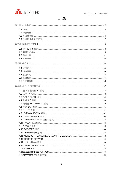
目录第一章产品概述 (3)1.1功能 (3)1.2一般规格 (3)1.3各部分名称 (4)1.4外型尺寸及安装方法 (7)第二章编辑软件TK100 (8)2.1 TK100基本概述 (8)2.2编辑用户画面 (8)2.3保存工程 (32)2.4下载画面 (33)第三章操作方法 (33)3.1联机通讯 (33)3.2切换画面 (34)3.3系统口令 (34)3.4修改数据 (35)3.5开关量控制 (36)第四章与PLC的连接方法 (37)4. 1深圳丰菱科技FL系列 (37)4.2三菱FX系列 (38)4.3西门子S7-200系列 (39)4.4欧姆龙C系列 (39)4.5施耐德NEZA/TWIDO系列 (40)4.6 台达DVP系列 (41)4.7松下FP系列 (41)4.8 LG Master-K CNet系列 (42)4.9 LG系列 Modbus 协议 (43)4.10 LG Master-K 120S 编程口通讯 (44)4.11 FACON永宏系列 (44)4. 12 光洋S系列 (45)4.13 ECOSTEP 系列 (46)4.14 AB Micrologix系列 (47)4.15 MODBUS RTU/ASCII/EMERSON/RTU EXTEND (48)4.16 MODBUS SERVER (49)4.17 九天丰菱自由协议 (50)4.18 SAIA PCD S-BUS协议 (51)4.19 VIGOR PLC (52)4.20 EMERSON EC20系列PLC (53)4.21 KEYENCE KV系列PLC (54)eView TK100 V1.0.0 组态软件Release Note (55)附录1:自由协议文档 (59)附录2:其它注意事项 (61)附录3:TK100组态新增功能 (62)第一章产品概述1.1功能TK100是一个小型的人机界面,主要与各类PLC(或带通信口的智能控制器)配合使用,以文字或指示灯等形式监视、修改PLC内部寄存器或继电器的数值及状态,从而使操作人员能够自如地控制机器设备。
- 1、下载文档前请自行甄别文档内容的完整性,平台不提供额外的编辑、内容补充、找答案等附加服务。
- 2、"仅部分预览"的文档,不可在线预览部分如存在完整性等问题,可反馈申请退款(可完整预览的文档不适用该条件!)。
- 3、如文档侵犯您的权益,请联系客服反馈,我们会尽快为您处理(人工客服工作时间:9:00-18:30)。
产而成,能更好地保存虾苗必需的重要活性成分,比如酶类、维生素、益生菌和不饱和脂肪酸。
这些成分在Zeigler的两款液体饲料中含量都非常高,特别是对虾苗生长发育至关重要的不饱和脂肪酸(DHA,EPA)。
《当代水产》:据悉,Zeigler公司的产品在国外已推广,能否介绍国外的一些使用情况或案例?
Ramir E.Lee:Zeigler公司在1986年就有第一个虾苗饲料产品。
目前,虾苗饲料产品线很全面,从蚤状幼体到池塘开口都有相应产品。
我们的产品已经出口超过40个国家,在世界各地都有非常多的客户,也被越来越多亚洲客户认可和接受。
举个大家比较熟悉的客户——美国迈阿密(SIS),它是全球最大种虾生产企业,我们已合作多年。
我们最有代表性的产品叫易卤虫,从字面理解就是比苗场使用的丰年虫更容易。
它是一款液体微胶囊包膜饲料,专门用来替代丰年虫,不像丰年虫卵需要孵化,可直接使用。
现墨西哥、巴西、厄瓜多尔、巴拿马、危地马拉、洪都拉斯,这些国家都已实现人工丰年虫100%替代天然丰年虫。
于2012年开始,我们在亚洲的越南、印度尼西亚、马来西亚已有早期的用户,市场份额在慢慢增长。
据生产实践数据,在合适条件下,从无节幼体培育至PL12,总成活率可达到60%。
当然这成活率与苗场管理密切相关。
但在条件合适的情况下,我们是可以帮助苗场做到这水平,并且能做到保持稳定生产。
其实,从生产角度看,使用Zeigler公司产品的成本比使用高质量野生卤虫卵廉价。
一般情况下,1kg卤虫卵可孵出2.5~3kg卤虫。
而易卤虫虽然是液体饲料,虽水份含量很高,但是和80%孵化率的干燥丰年虫卵进行等量替代,也就是1kg易卤虫的营养相当于1kg强化后的高品质卤虫卵。
在中国,我们建议结合苗场实际情况和操作手法,逐步提高替代比例。
只有中国本地技术员彻底了解这产品后,我们才推荐进行100%替代。
就算刚开始不进行替代,只是进行营养加强,或者只是在苗场丰年虫孵化供应不上时来使用易卤虫,都是非常有意义的。
从使用便捷性看,Zeigler公司产品不需人工去孵化虫卵,可随时使用,极大方便了客户使用。
从产品营养成分稳定性看,卤虫卵采收季节、年份等不同,卤虫质量会有较大差异,而Zeigler公司产品都是人工配合饲料,是按天然卤虫的营养成分配制出来,它们的营养成分一样,可使苗场标准化生产。
《当代水产》:据悉,Zeigler公司有一个研究方向是超高密度养殖,能否介绍下?Ramir E.Lee:美国没有养虾,美国人食用的都是进口冷冻虾。
在美国和欧洲,对虾养殖是新兴产业,如果你在美国发展养虾业,意味着可以给市场提供新鲜虾,是很受市民欢迎,但他们不用池塘养殖,是高密度室内全循环水养殖。
在这情况下,养殖密度比较大,生态环境需要处理,养殖用水要达到100%的循环,而且美国的废水排放标准非常高。
基于这样的市场,美国优秀科研机构——德克萨斯州立大学奥斯汀分校大力研究高密度室内全循环水养殖,研究除关注品质、养成率等外,还要考虑经济性问题,利用高密度室内全循环水养出的虾不能比冷冻虾贵太多。
为什么要高密度,就是为了降低成本,饵料就起到决定性作用,而他们研究所用饵料都由Ziegler公司提供。
可以说Ziegler公司是世界上唯一一家室内100%循环水高密度养鱼虾的人工饵料生产企业,在这领域的领先度非常高。
简单地说,他们可以做到收虾时的养殖密度大于400尾/m3,几乎零换水,生长速度大于
2g/周。
这体现了Zeigler卓越的营养调控技术和世界一流的饲料水稳定性技术。
每个Zeigler客户都和我反馈,Zeigler产品对水质影响非常小。