D型连接器规格
优联康D-SUB连接器产品的分类方式
高密度D-SUB26PIN包线式连接器母头,高密度D-SUB26PIN包线式连接器公头,
高密度D-SUB44PIN包线式连接器母头,高密度D-SUB44PIN包线式连接器公头,
高密度D-SUB62PIN包线式连接器母头,高密度D-SUB62PIN包线式连接器公头,
D-SUB25PIN90度插板式连接器母座,D-SUB25PIN90度插板式连接器公座,
D-SUB37PIN90度插板式连接器母座,D-SUB37PIN90度插板式连接器公座,
D-SUB50PIN90度插板式连接器母座,D-SUB50PIN90度插板式连接器公座。
8.高密度D-SUB包线式连接器,规格如下:
大电流D-SUB13W3直插式连接器,
大电流D-SUB13W6直插式连接器,
大电流D-SUB17W2直插式连接器,
大电流D-SUB21W1直插式连接器,
大电流D-SUB21W4直插式连接器,
大电流D-SUB24W7直插式连接器,
大电流D-SUB25W3直插式连接器,
大电流D-SUB17W2焊线式连接器,
大电流D-SUB21W1焊线式连接器,
大电流D-SUB21W4焊线式连接器,
大电流D-SUB24W7焊线式连接器,
大电流D-SUB25W3焊线式连接器,
大电流D-SUB27W2焊线式连接器,
大电流D-SUB36W4焊线式连接器,
高密度D-SUB44PIN焊线式连接器母头,高密度D-SUB44PIN焊线式连接器公头,
高密度D-SUB62PIN焊线式连接器母头,高密度D-SUB62PIN焊线式连接器公头,
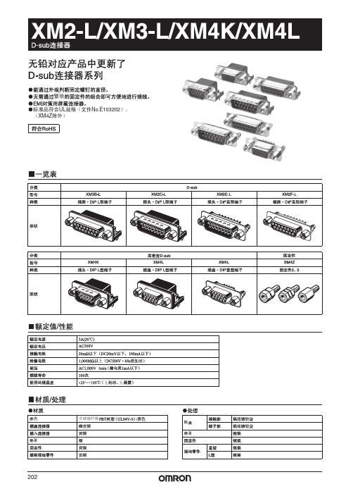
欧姆龙 XM2-L XM3-L XM4K XM4L D-sub 连接器 说明书
注1. 注2.
不插入面板 XM4Z-001□ XM4Z-001□ XM4Z-101□ XM4Z-101□
插入面板 XM4Z-002□ XM4Z-002□ XM4Z-102□ XM4Z-102□
市售螺母 不要
不要 不要 需要 不要 需要 不要
207
208
φ0.6 D
UNC #4-40
8.3
12.55
6
6.2
7
3.8
3.4
2.84 10.7
印刷基板加工尺寸 (t=1.6mm、BOTTOM VIEW)
2-φ3.2
+0.1 -0
N-φ1±0.1
2.77±0.1 B±0.1
E±0.1
2.84±0.1
尺寸表 极数(N) 9 15 25
A
B
C
D
E
30.8 24.99 16.92 19.23 6.96
M3×0.5
#4-40 UNC
5
5.8
10.0
XM4Z-1012
M3×0.5
#4-40 UNC
5
5.8
11.8
XM4Z-0013
#4-40 UNC
#4-40 UNC
5
5.8
10
XM4Z-1013
#4-40 UNC
#4-40 UNC
5
5.8
11.8
5
5.8
10.0
XM4Z-0021
M2.6×0.45
#4-40 UNC
2.84
(3.9)
5.8
A B C 2.77
UNC #4-40
7.9
1.6 5.8 8.1 2.84
(单位 :mm)
ERNI TMC系列小型D型连接器说明书

Trapezoidal-Connectors Series TMC Subminiature-D Connectorsto DIN 41 652/IEC 807-3GeneralSeries TMC connectors are available in 5 different housing sizes with 9, 15, 25, 37 and 50 pins. In applications these connectors are frequently used for interface connections.Owing to the various sizes of housing series TMC connectors match v irtually any application.Wires can be connected by manual soldering, insulation displacement and crimping. For use on PC boards there are versions with straight or angled pins for machine soldering. For versions with straight pins there is also the solderless press-fit technique (ERNIPRESS).You can find ordering details for connectors with crimp terminiation a nd E RNIPRESS o n s eparate d ata s heets. AccessoriesFor series TMC connectors ERNI has a wide range of acces-sories available.No matter whether the important criterion is easy assembly, different types of mounting, electromagnetic compatibility, locking devices or connector housings, you will find attractive solutions at ERNI.Main features• Indirect mating system• International approval certificates such as UL and CSA • 5 housing sizes with 9, 15, 25, 37 and 50 pins• Accessories integrated into the connector• Tinned m etal h ousing• Laminated ground contact on the male housings for optimal screening• 3 different connector housing types available• Various t ypes o f t ermination a vailable• Solid contacts on the male connectors with tinned manual soldering terminationTerminationFor ERNIPRESS, crimping and insulation displacement (IDC) there are separate data sheets available. Performance Levels207 to DIN 41 652/IEC 807-3MIL-C-24308, CCTU 08-14and IEC-Recommendation 48 B200 mating cyclesContact zone gold-platedterminal zone tinned201 as for version 207 butterminal zone gold-plated 107 to DIN 41 652/IEC 807-3MIL-C-24308, CCTU 08-14and IEC-Recommendation 48 B500 mating cyclesContact zone gold-platedterminal zone tinned101 as for version 107 butterminal zone gold-platedPerformance level 107 and 101 connectors are available on request.Approval CertificatesUL All male and female connectors from this data sheet are approved by the American certification authority …Under-writers Laboratories Inc.“.File no. E 84703 CSA All types are listed by the Canadian certification author-ity …Canadian Standards Association“.File Nr. LR 62503 and LR 62504.D-SubIntegrated AccessoriesRiveted nut (see fig. 1)On the version with riveted nut there is a nut riveted into the mounting flanges of the connector so that it cannot twist. The thread is available as a M3 and 4/40" version. This facilitates fitting into housings or front panels.Threaded bolt (see fig. 2)To ensure secure connector locking, a screw locking device is frequently used with threaded bolts. TMC connectors from ERNI are available with riveted threaded bolts. These hexagon bolts are available with internal threads of M3 and 4/40". For the user it means there is no need for loose accessories.Spacer bolt (see fig. 3)Due to the design of the TMC connectors a spacer is required for vertical assembly on pc boards. These parts are supplied by ERNI as individual accessories.Ground pin (see fig. 4)The additional ground pin is designed for connecting up to the pc board chassis contact for example. Spacer bolt with mounting clip (on request)(see f ig. 5)These spacer bolts can be snapped into the mounting holes on the pc board. If the holes are plated-through there will also be a solder joint.Ground clip (see fig. 6)For screening contact there are angled ERNI TMC connector ground clips available. These clips are soldered into the mounting holes on the pc board, thus creating a firm chassis connection.Ground bar (see fig. 7)Ground bars on angled connectors are attached to the guide frame on the pc board. This makes it possible to make connection with chassis conductors on the pc board.Ground eyelet (on request) (see fig. 8)With the ground lug the chassis contact can be soldered on.Tinned metal housings and laminated ground contactsThe metal housings on the TMC connectors (standardversions) from ERNI are tinned so as to achieve better contact for the chassis connection. Specially punched grooves on the metal protective collar of the male connectors ensure reliable contact. Together with the ERNI connector housings in the metallized version and grounding accessories on the connec- tors an optimal electromagnetically compatible application is achieved.Solid punched male contactsDue to a special manufacturing process we are in a position to offer solid punched male contacts.These versions have a tinned terminal zone and are suitable for a current-carrying capacity of up to 7.5 A.Guide frame for angled connectorsFor mounting purposes and better guidance of angled TMC connectors with pins for dip-soldering the standard versions are equipped with a guide frame made of plastic.With this guide frame the connectors can be screwed or riveted onto pc boards.Versions with a guide frame and mounting clip are clipped into the pc boards and soldered in place.D-SubElectrical and mechanical dataVersionsTMC-male connectors to PerformanceLevels 207 and 201TMC-female connectors to Performance Levels 201TMC-female connectors toPerformance Level 207Numbers of pins 2-rows of 9, 15, 25, 37 and 3-rows of 50 contactsTemperature range-65°...+125° CPermissible humidity Annual average ≤ 80%, max. 100%Creepage and clearance ≥ 1,0 mmWorking current 7,5 A max. 5 A max. Test voltage 1250 V rms 1000 V rms Contact resistance ≤ 2,5 mΩ≤ 10 mΩInsulation resistance ≥ 1014ΩShock and vibration proofness No discontinuity at 20 g and 10...2000 HzShock proofness up to 50 gMetal protective collar Tinned steelMR St 4, 1+1 µm Ni, 8±2 µm SNMoulding PBT 30% GVInflammability of the plastic Non flammable as per UL 94 V-0Comperative creepagefigure to CTI 275 / CTI 175 MDIN IEC 112 for PBTService life Performance Level 2 ≥ 250 mating-cyclesContact force perfemale element 0,4 NExample of how to order023122 023123 023124 023125 023126*Dimension tablesPin connectors (P)D-Sub Socket connectors (S)Termination for the versions listed in this data sheetLoe = Solder eyelet tinned (male connector)L = Solder cupTL = Straight solder pin termination for print assemblyLP = Angled solder pin termination for print assembly (with and without guide frame)W = Wire-wrap terminationContact identification (wiring side)9 pins 15 pins 25 pins 37 pins 50 pinP S P S P S P S P STMC with manual soldering terminationDimensional drawingsMale connector Female connectorOrdering details004617004620004613 004926 004615Assembly detailsTMC with manual solder terminationAssembly c utoutZone of reliable contactFront assemblyRear assemblyD-SubTMC with straight dip-solder terminationDimensional drawingsMale connector Female connectorDimensional drawings023132 023133 023019 023134 023135*003552003553003554 003555 013920023136 023137 023138 023139 023140*003634013052003625 013702 013897023141 023142 023143 023144 023145*003633013551003626 013701 013898023146 023147 023148 023149 023150*003635013550003628 013700 013892023151 023152 023153 023154 023155*003636013549003627 013699 013893023156 023157 023158 023159 023160*013032013033013029 013034 013641 Assembly detailsTMC with straight dip-solder terminationPC board Zone of reliablecontactSpacer sleeve(available as integrated accessory)PC board hole patterns9 – 37 pin 50 pinD-SubTMC with straight dip-solder termination (with guide frame)Dimensional drawingsMale connector Female connectorOrdering details023********* 023173 023174 023175*003599013533003622 013707 013894023176 023177 023178 023179 023180* 003598 013532 003621 013708 013895023********* 023183 023184 023185*003600013535003623 013710 013899023********* 023188 023189 023190*003601013534003624 013709 013900D-Sub 023191 023192 023193 023194 023195*023196023197023198 023199 023200023201 023202 023203 023204 023205*023206023207023208 023209 023210023249 023250 023251 023252 023253*023279023280023281 023282 023283023211 023212 023213 023214 023215*023254023255023256 023257 023258023216 023217 023218 023219 023220*013973434287023259 023260 023261023221 023222 023223 023224 023225*023262023263023264 023265 023266023226 023227 023228 023229 023230*003585004225003608 023367 023268023284 023285 023286 023287 023288*003584013541003464 023304 023305023289 023290 023291 023292 023293*003583004925003606 023306 434705433196 023231 023232 023233 023234*433197023049023082 023269 023270023235 023236 023237 023238 023239*023104023271023272 023273 023274013966 023240 023241 023242 023243013965023275003605 023276 004869023244 023245 023246 023247 023248*003581013542013834 023277 023278023294 023295 023296 023297 023298*003579013014023307 004448 023308023299 023300 023301 023302 023298*003580023309003603 023310 023311For further accessories and other combination options please consult ERNI’s local office sales.Assembly detailsTMC with straight dip-solder terminationPC boardZone of reliable contactPC board hole patterns50pin9 – 37 pinMale connector Female connectorOrdering details about special version with solder pitch of 2.84 mm023312023314023317023318023319 023320Due to the wider pitch between the rows, there is more space for conductors on the PC board.The clearance and creepage ages are greater on these versions. PC board hole patterns9 – 37pinSpecial version with solder pitch of 2.84 mm between the rows TMC with angled dip-solder termination (solder pitch 2.84 mm)Dimensional drawingsD-SubTMC with angled dip-solder termination (without guide frame)Integrated accessories are also available on request for TMC connectors with angled terminals without guide frame.For assembly, an assembly comb is available on request.Dimensional drawingsMale connectorFemale connectorOrdering details023322 023323 023324 023325 023326*013487013525013624 013714 013930Assembly detailsTMC with angled dip-soldered termination without guide frameD-SubZone of reliablecontactPC boardPC boardPC board hole patterns50pin9 – 37 pinTMC with wire wrap terminationsDimensional drawingsMale connectorFemale connectorOrdering details023327023328 023329 023330 023331*013492013553013632 013698 013928Screw locking accessories (for all TMC standard version connectors) Ordering details434831434830434832434833。
D型连接器:美宇航级,工业级,军级一览表
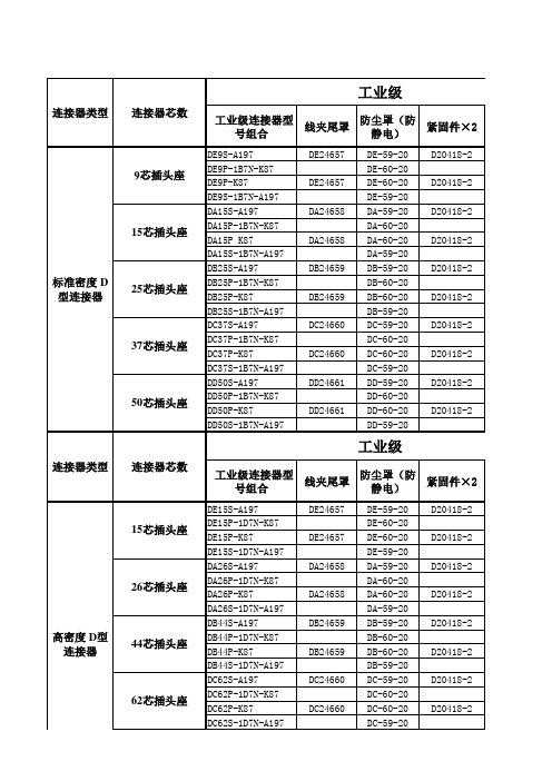
防尘罩(防静 电)
DE-59-20 DE-60-20 DE-60-20 DE-59-20 DA-59-20 DA-60-20 DA-60-20 DA-59-20 DB-59-20 DB-60-20 DB-60-20 DB-59-20 DC-59-20 DC-60-20 DC-60-20 DC-59-20 DD-59-20 DD-60-20 DD-60-20 DD-59-20
9芯插头座
15芯插头座
标准密度 D 型连接器
25芯插头座
37芯插头座
50芯插头座
工业级
连接器类型 连接器芯数 工业级连接器型 防尘罩(防 线夹尾罩 紧固件×2 号组合 静电)
DE15S-A197 DE15P-1D7N-K87 DE15P-K87 DE15S-1D7N-A197 DA26S-A197 DA26P-1D7N-K87 DA26P-K87 DA26S-1D7N-A197 DB44S-A197 DB44P-1D7N-K87 DB44P-K87 DB44S-1D7N-A197 DC62S-A197 DC62P-1D7N-K87 DC62P-K87 DC62S-1D7N-A197 DE24657 DE24657 DA24658 DA24658 DB24659 DB24659 DC24660 DC24660 DE-59-20 DE-60-20 DE-60-20 DE-59-20 DA-59-20 DA-60-20 DA-60-20 DA-59-20 DB-59-20 DB-60-20 DB-60-20 DB-59-20 DC-59-20 DC-60-20 DC-60-20 DC-59-20 D20418-2 D20418-2 D20418-2 D20418-2 D20418-2 D20418-2 D20418-2 D20418-2
通用D型连接器尺寸

4.75
5.8 10
4.75
4.8 11.8
4.75
4.8 10
XM4Z-1013
#4-40 UNC #4-40 UNC
XM4Z-0023
#4-40 UNC #4-40 UNC
XM4Z-1023
#4-40 UNC #4-40 UNC
4.75
5.8 10.0
4.75
4.8 11.8
4.75
4.8 10.0
N-φ1±0.1
8.1±0.1 2.84±0.1
(3.9) 1.6 6 18.6 12.55
2.77±0.1 B±0.1
D±0.1
5.8
尺寸表 极数(N) 9 15
3.18
X M 2 � L / X M 3 � L / X M 4 K / X M 4 L
8.1 2.84
A 30.8 39.1 53.0
+0.1 0.25 15-φ1.0 0 24.99±0.1
5.8
2.54
8.89
22.2
2.54 2.54 3.5 (3.94)
●高密度D-sub 插座�DIP L型端子 XM4L-1542-132
30.8 24.99 16.33 2.29 1.145 1.98
5 10 15 1 6 11
印刷基板加工尺寸 (t=1.6mm、 BOTTOM VIEW)
3.25
φ0.6 19.23
●固定件2 XM4Z-0011
M2.6×0.45 2.7 #4-40 UNC 0.4
●固定件3 XM4Z-1011
2.7 M2.6×0.45 #4-40 UNC 0.4
XM4Z-0021
2.2 M2.6×0.45 #4-40 UNC 0.4
专用D-SUB 规格书

REVISION: ECR/ECN INFORMATION: SHEET No.EC No:DTITLE:D-SUB REC.CONNECTOR1 of 51.0 Applicable Connector: Applicable to DLK D-SUB Series connector.(适用于德力康公司D-SUB 系列连接器.)Scope: This specification covers the requirements for product performance and test methods of DLK’s D-SUB Series Connectors of the part numbers specified as bellow.(覆盖范围:此规格书内容含盖德力康公司D-SUB 系列连接器产品性能及测试方法。
) 2.0 Rating (要求):2.1 Rated Voltage : 250 V AC,DC (额定电压:250V ) 2.2 Rated Current:1.0 A (额定电流:1.0A )2.3 Electric Pressure: Keeping 60 second in AC 500V/1mA(耐压500V AC 持续60秒) 2.4 Insulation Resistance: 5000 M Ω Min. in DC 500V (绝缘阻最小5000兆欧) 2.5 Contact Resistance: 30 m Ω Max. (接触阻抗最大30毫欧)3.0 Test Condition (测试条件):All tests shall be performed as bellow conditions unless otherwise specified. (所有的测试都在下列条件下完成,除非另有说明.)3.1 Temperature range : +15℃to35℃. ( 温度:+15℃至35℃) 3.2 Humidity range: 25%to85%.(湿度:25%至85%) 3.3 Atmospheric Pressure : 860 to 1060 mber (大气压力: 860 至 1060兆帕)4.0 Mechanical Characteristics (机械性能) 4.1 Insertion Force(for one pin):240gf/Max.4.2 Extraction Force(for one pin): 30gf/Min.4.3 Stretching Force(from insulator to pin):1.0Kgf/Min 4.4 Insertion Force(mating connector):2.0 to5.0Kgf; 4.5 Extraction Force(mating connector):1.0Kgf Min 5.0Test Methods and Requirements (测试方法和要求): 5.1Examination of product (检查尺寸):Item (条目)Test Description (测试内容)Test Methods (测试方法)Requirement (要求)REVISION: ECR/ECN INFORMATION: SHEET No.EC No:DTITLE:D-SUB REC.CONNECTOR2 of 55.1.1Examination of product Outward Appearance Structure (产品外形/尺寸检查)Shall be confirm with eyes in accordance witheach drawing. Shall be confirmed by using proper measuring instruments.(依照图面要求对产品目视检查,再用测量工具,按图面要求测量尺寸)Outward appearance shall be good without such injurious problem structure shall be meet the designand dimensional requirements of drawing(外观良好,无任何有害问题;结构符合图面设计要求。
d型接头标准

D型接头是一种常见的电子连接器,它广泛应用于音频、视频、数字信号等领域。
D型接头有许多不同的标准,本文将详细介绍常见的D型接头标准及其特点。
一、D型接头标准简介D型接头最早是由Cannon公司于1938年推出,并被用于军事和航空应用领域。
后来,它逐渐应用于民用领域,成为了通用的电子连接器之一。
如今,D型接头已经成为了音频、视频、数字信号等领域中最常见的连接器之一。
二、D型接头标准分类D型接头根据其针脚数量和形状不同,可以分为多个不同的标准。
常见的D型接头标准包括:1. D-sub 9:9针D型接头,也称为DB-9接头,用于串口通讯。
2. D-sub 15:15针D型接头,也称为DB-15接头,用于VGA 显示器。
3. D-sub 25:25针D型接头,也称为DB-25接头,用于并口通讯。
4. D-sub 37:37针D型接头,也称为DB-37接头,用于打印机等设备连接。
5. HD D-sub:高密度D型接头,也称为DD50接头,具有更小的尺寸和更高的针脚密度,用于数字信号传输。
6. Combination D-sub:组合式D型接头,可以将几个不同的信号通道集成在一个接头内。
三、D型接头标准特点1. 耐用性强:D型接头采用金属外壳,具有较好的耐用性和抗干扰能力。
2. 信号传输稳定:D型接头针脚排列紧密,能够保证信号传输的稳定性和可靠性。
3. 安全性高:D型接头采用螺纹锁紧机构,可以确保连接器的牢固性和安全性。
4. 多用途性强:D型接头具有多种针脚数量和形状,适用于不同领域和应用场合。
5. 易于安装:D型接头具有标准化的尺寸和接口,易于安装和维护。
四、D型接头的应用领域D型接头由于其稳定性、可靠性和多用途性等特点,被广泛应用于以下领域:1. 音频设备:D型接头可以用于音频设备中的麦克风、耳机等连接。
2. 视频设备:D型接头可以用于显示器、投影仪等视频设备的连接。
3. 数字信号传输:D型接头可以用于数字信号传输领域,如计算机网络、串口通讯等。
常用接插件型-自己总结

常用接插件型-自己总结常用接插件型是一种常见的插件连接器,它由多个接插件组成。
这些接插件可以通过插头和插座进行连接,以实现电气和机械信号的传输。
常见的接插件型包括D型接插件、USB接插件和RJ45接插件等。
D型接插件是一种常用的多针头接插件,它通常用于连接计算机和外设设备,如打印机、键盘和鼠标等。
D型接插件有许多不同的规格和大小,常见的有D-Sub 9、D-Sub 15和D-Sub 25等。
这些接插件具有可靠的连接性能和良好的防护性能,能够有效地传输数据和信号。
USB接插件是一种常见的通用串行总线接口,广泛应用于计算机和外设设备之间的连接。
USB接插件具有方便易用、可插拔和高传输速度的特点,支持热插拔和即插即用。
常见的USB接插件有Type-A、Type-B、Micro-USB和Type-C等,其中Type-C接插件的兼容性更广,能够支持更快的数据传输速度和更高的功率传输。
RJ45接插件是一种常用的网络接插件,它通常用于连接计算机和网络设备,如路由器、交换机和调制解调器等。
RJ45接插件具有可靠的连接性能和良好的抗干扰性能,能够支持高速以太网和局域网的连接。
它使用8个金属插针来传输数据信号,其中4个插针用于发送数据,4个插针用于接收数据。
除了上述常用的接插件型,还有许多其他类型的接插件,如音频接插件、视频接插件和电源接插件等。
音频接插件通常用于连接音频设备,如扬声器、耳机和麦克风等。
常见的音频接插件有3.5mm立体声插头和XLR插头等。
视频接插件通常用于连接视频设备,如显示器、摄像机和电视机等。
常见的视频接插件有HDMI接口、VGA接口和DVI接口等。
电源接插件通常用于连接电源设备,如电源适配器和电池等。
常见的电源接插件有电源插头和插座等。
总之,常用接插件型是一种常见的插件连接器,它由多个接插件组成,用于实现电气和机械信号的传输。
常见的接插件型包括D型接插件、USB接插件和RJ45接插件等,它们具有不同的特点和应用场景。
- 1、下载文档前请自行甄别文档内容的完整性,平台不提供额外的编辑、内容补充、找答案等附加服务。
- 2、"仅部分预览"的文档,不可在线预览部分如存在完整性等问题,可反馈申请退款(可完整预览的文档不适用该条件!)。
- 3、如文档侵犯您的权益,请联系客服反馈,我们会尽快为您处理(人工客服工作时间:9:00-18:30)。
-25℃~+70℃85%RH MAX
StorageTemperatureRange
-40℃~+70℃85%RH MAX
3.TEST STANDARD
Unless otherwise specified, the standard range of atmosphericconditions for making measurements and tests are as follows
25.4mmper minute.
JIS C5402-6.6
The test Mate Plug Ref to attachment (3)
Keeping
Force
3NMin
12
Humidity-
Temperature
cycling
Subject Mated connect to
temperature changes
JIS C5402-6.3
Appearance
No damage
Contact Resistance
(Before test)
30mΩ Max
(After test)
50mΩ Max
Mating
force
(Before test)
50N Max
(After test)
42NMax
Un-mating
(Before test)
JIS C5402-6.6
The test Mate Plug Ref to attachment (2)
Un-mating
force
4.5N Min
7
Durability
test
Mate and un-mate each connector shall be made with the mating plug and jack for1000cycles repeatedly at maximum rate of 500±50cycles per hour.
Dielectric withstanding voltage
500V(AC)
15
Resistance to
Soldering heat
Solder bath method:
Solder temperature 265±5℃,
Immersion time: 10±1Sec,Depth up to the surface of the board1.6mm.
No damage/
deformation
Dielectric withstanding voltage
500V(AC)
Mechanical Performance
5
Connector
Mating Force
Operation Speed:25.4mm/min. Measure
the force required to mate connector.
Revision
Revision Description
PAGE
Date
B0
New release
ALL
2009.10.16
1.SCOPE
This specification is applied to the requirements forVGA,DVIconnector .This specification covers the materials,electrical, mechanical and environmental performance of the applicable product description and test method.
JIS C5402-7.3
Appearance
No damage
Contact Resistance
(Before test)
30mΩ Max
(After test)
50mΩ Max
InsulationResistance
(Before test)
100MΩMin
(After test)
50MΩMin
JIS C5402-7.10
Appearance
No damage
Contact Resistance
(Before test)
30mΩ Max
(after test)
50mΩ Max
10
Cold Resistance
Mate connectors and expose to -25±3℃for96hours. Upon completion of the exposure period, the test specimens shall be conditioned at ambient room conditions for 1 to 2 hours, after which the specified measurements shall be performed.
EIA-364-52A
Appearance
95% coverage as measured ,
no voids,
pin holes
17
Salt spray
Mate connectors and expose to
thefollowing salt mist conditions:
NaCl solution concentration:5±1%
EIA-364-56C
Appearance
No damage
16
Solder-ability
Dip solder tails into the molten solder
(held at 245±5℃)upto2-3mmfrom the bottom of the housingfor5.0±0.5 seconds.
2.2Materials
Refer to the drawing.
2.3 Relateddocuments
D-SUB:EIAJ RC-5237
2.4 Rating
Item
Standard
Rated Voltage (Maximum)
DC:12V
Rated Current (Maximum)
DC:1.0A
3.1Ambient temperature:5℃to35℃
3.2Relative humidity:45% to 85%
3.3Air pressure:86Kpa to 106 Kpa
3.4 Test Requirements and Procedures Summary
Item
Test Conditቤተ መጻሕፍቲ ባይዱon/Method
JIS C5402-5.3
30mΩ Max
3
Insulation
Resistance
500VDC is applied between any contacts.
JIS C5402-5.2
100MΩMin
4
Withstanding
voltage test
Apply AC 500V at sea level
JIS C5402-6.1
Appearance
No damage
Contact Resistance
(Before test)
30mΩ Max
(after test)
50mΩ Max
Discontinuity
1μsec Max
EnvironmentalPerformance
9
Heat Resistance
Spray timepleace refor to Customer drawing.
Ambient temperature:35±2℃
EIA-364-26B
Appearance
Without noticeable rust
JIS C5402-7.10
Appearance
No damage
Contact Resistance
(Before test)
30mΩ Max
(after test)
50mΩ Max
11
Single Terminal
Keeping force
Apply a pull out force in the axial direction of the contact at a rate of
on mated and Un-mated connectors for 1 minutes , while applying the voltage, the leakage current is monitored and shall be less than2mA.
JIS C5402-5.1
Appearance
Mate connectors and expose to70±2℃for96hours. Upon completion of the exposure period, the test specimens shall be conditioned at ambient room conditions for 1 to 2 hours, after which the specified measurements shall be Performed.
2.REQUIREMENTS
2.1Design and Construction
Product shall be of the design, construction and physical dimensions specified on the