泳池系统使用说明书
游泳池设备使用说明书
游泳池设备使用说明书一、安全须知1. 在使用游泳池设备前,请务必仔细阅读使用说明书,并按照指示正确操作。
若不熟悉设备使用方法,请向工作人员咨询。
2. 使用游泳池设备时,应注意自身安全,避免踩踏、碰撞或抓住设备构件,以免发生意外。
3. 若在使用过程中发现设备出现故障或异常情况,请立即停止使用并联系维修人员进行检修。
二、设备说明1. 游泳池设备包括但不限于游泳池水质处理设备、游泳池边缘设备、海滩椅、游泳圈等。
2. 游泳池水质处理设备主要负责对游泳池水进行过滤、杀菌和消毒,以确保游泳池水质清洁卫生。
3. 游泳池边缘设备主要是指游泳池周边的护栏、楼梯、扶手等构件,用于提供游泳者上下池的便利和安全。
4. 海滩椅是供游泳池边的休憩区域使用,提供舒适的休息环境。
5. 游泳圈是供游客在游泳池中玩耍和浮动使用的装备,用户在使用时应注意安全,避免溺水等危险情况。
三、使用步骤1. 游泳池水质处理设备的使用步骤:a. 确保水质处理设备正常运行及电源连接无误。
b. 请按照设备指示,加入适量的消毒剂和调节剂。
c. 启动设备,根据设备说明调整过滤和杀菌的时间和强度。
d. 定期清理和更换滤芯及其他配件,保证设备正常运行。
2. 游泳池边缘设备的使用步骤:a. 游泳池边缘设备的安装应在游泳池建设完成后进行。
b. 确保游泳池边缘设备安装牢固可靠,无棱角及其他危险因素。
c. 游泳池边缘设备的清洁和维护应定期进行,确保其使用安全。
3. 海滩椅的使用步骤:a. 游泳池边缘设备的摆放应均匀,保持整齐。
b. 使用时,请留意椅面是否平稳,座垫是否干燥。
c. 使用完毕后,请清理并放回指定位置,保持环境整洁。
4. 游泳圈的使用步骤:a. 请确认游泳圈的充气情况,确保无漏气和破损。
b. 检查游泳圈的材质和尺寸是否适合使用者,避免安全隐患。
c. 使用游泳圈请在游泳池浅水区域,避免深水区域造成危险。
四、维护保养1. 游泳池设备的维护保养应由专业人员进行,定期检查设备的工作情况,并及时维修、更换损坏的配件。
泳池机房操作说明
泳池水处理系统设备操作及安装工程机房设备操作说明设备调试运行操作一、机房安全用电规范1、机房一切设备必须有专业管理人员来操作。
2、机房内须保持好清洁卫生,要有良好的通风、照明条件,给设备提供一个好的散热环境。
3、机房工作人员需要离开当前用电工作环境,应检查并保证工作环境的用电安全。
4、机房人员应学习常规的用电安全操作知识,了解机房内部的供电、用电设施的操作规程。
5、机房人员应经常学习、掌握机房用电应急处理步骤、措施和要领。
6、机房应安排有专业资质的人员定期检查供电、用电设备、设施。
7、严禁随意对设备断电、更改设备供电线路,严禁随意串接、并接、搭接各种供电线路。
8、系统内的工作参数稳定在所需的设定值上,严禁随意调节改变参数。
9、最后离开机房的工作人员,应检查所有用电设备,应关闭长时间带电运作可能会产生严重后果的用电设备。
二、操作前准备检查过滤器/吸附罐本体及附属的各种阀门、管路、仪表和各种设备附件是否完好;检查循环水泵、电气设备、各种现场仪表及各种附属设施是否完好;确认循环管路相应的阀门按照要求开启或者关闭。
三、泳池注水操作1.先关闭泳池“泄水阀门”,再打开“自来水给水阀门”,泳池水及机房均衡水箱注满后关闭“给水阀门”即可。
注意:1.泳池给水阀门位于水处理机房内,已标记;2.如果采用海水系统进行池水补水,关闭自来水补水阀门,开启海水系统供水泵(开启之前确认海水水箱内的水是进行循环过滤后的水,否则要先对海水水箱内的水进行过滤循环之后再使用,详见海水系统操作说明)。
四、吸污操作流程关闭水泵和水箱之间的阀门,打开吸污管上阀门;吸污口上接上吸污胶喉、池底擦头和伸缩杆等吸污配套设备,打开过滤循环泵开始吸污。
吸污回水经过过滤设备时,可以将过滤设备调到过滤状态(filter)进行过滤,也可以将过滤设备调到排放状态(waste)直接排放至集水井。
每次吸污之后,打开水泵头的活动盖,把水泵头的过滤网的水叶和杂物倒出来,然后将活动盖拧好。
泳池机功能说明书-通用方案
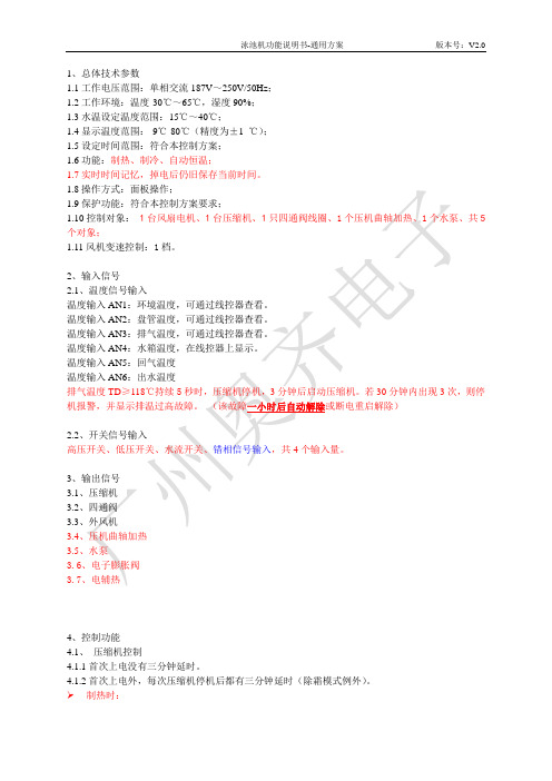
1、总体技术参数1.1工作电压范围:单相交流187V~250V/50Hz;1.2工作环境:温度-30℃~65℃,湿度90%;1.3水温设定温度范围:15℃~40℃;1.4显示温度范围:-9℃-80℃(精度为±1 ℃);1.5设定时间范围:符合本控制方案;1.6功能:制热、制冷、自动恒温;1.7实时时间记忆,掉电后仍旧保存当前时间。
1.8操作方式:面板操作;1.9保护功能:符合本控制方案要求;1.10控制对象: 1台风扇电机、1台压缩机、1只四通阀线圈、1个压机曲轴加热、1个水泵、共5个对象;1.11风机变速控制:1档。
2、输入信号2.1、温度信号输入温度输入AN1:环境温度,可通过线控器查看。
温度输入AN2:盘管温度,可通过线控器查看。
温度输入AN3:排气温度,可通过线控器查看。
温度输入AN4:水箱温度,在线控器上显示。
温度输入AN5:回气温度温度输入AN6:出水温度排气温度TD≥118℃持续5秒时,压缩机停机,3分钟后启动压缩机。
若30分钟内出现3次,则停机报警,并显示排温过高故障。
(该故障一小时后自动解除或断电重启解除)2.2、开关信号输入高压开关、低压开关、水流开关、错相信号输入,共4个输入量。
3、输出信号3.1、压缩机3.2、四通阀3.3、外风机3.4、压机曲轴加热3.5、水泵3.6、电子膨胀阀3.7、电辅热4、控制功能4.1、压缩机控制4.1.1首次上电没有三分钟延时。
4.1.2首次上电外,每次压缩机停机后都有三分钟延时(除霜模式例外)。
制热时:4.1.3开机条件:实际水温T2≥设定温度+Y℃,压缩机停止。
4.1.4停压缩机OFF:压缩机ON:水箱温度设定温度-X℃设定温度+Y℃其中X其中Y制冷时:4.1.54.1.6压缩机压缩机ON自动时:4.1.7实际水温T24.1.8实际水温T24.1.9运行超过10分钟时,压机停机,退出该状态;4.1.10故障状态下,不运行4.2、室外风扇控制4.2.1压缩机开机前,室外风扇要提前5秒钟运行。
游泳池使用说明书

游泳池使用说明书首部:欢迎您选择使用本游泳池设施,请仔细阅读以下使用说明,以确保您的安全和舒适使用。
一、安全须知为了保证您的安全,请务必遵守以下规定:1. 年龄限制:未满12周岁的儿童需在成年人的陪同下使用游泳池。
2. 心脏病或其他严重疾病患者需在医生的允许下方可使用游泳池。
3. 请勿在游泳池附近跑动、嬉闹或打闹,以免发生意外。
4. 游泳池设有深浅区,在非潜水区域内切勿潜水。
5. 若人数过多,请遵守现场工作人员的引导以确保安全。
二、使用时间游泳池开放时间:每天早上8点至晚上10点。
三、入场须知1. 入场费:成人每次入场收费10元,儿童每次入场收费5元。
2. 用户凭证:持有效入场券或会员卡方可入内使用游泳池。
3. 会员卡:欢迎办理游泳池会员卡,会员享受更多优惠待遇。
四、入场流程1. 排队入场:请在入口处排队等候,以确保有序入场。
2. 入场登记:请出示有效入场凭证,工作人员会进行入场登记。
3. 寄存物品:请将贵重物品存放在指定的寄存柜内,本游泳池不对遗失负责。
4. 更衣室:请统一使用更衣室更换泳装,切勿在公共区域更换。
五、游泳池设施使用说明1. 淋浴区:入场前请使用淋浴,务必保持身体清洁。
2. 游泳池:请根据自身能力选择合适的泳池区域,切勿逾越深度线。
3. 游泳圈、浮板等游泳辅助器材:如需使用,请谨慎选择,并按照工作人员的指示正确佩戴。
4. 滑水道:仅限于身高超过1.2米的游客使用,使用时请排队等候。
5. 游泳救生员:游泳池设有专业救生员,如遇紧急情况,请立即向其寻求帮助。
六、禁止事项为了保证游泳池的正常运营,禁止以下行为:1. 携带食品、饮料或玻璃制品进入游泳池区域。
2. 吸烟或使用明火,如需吸烟请到指定的吸烟区域。
3. 在游泳池内大声喧哗或进行危险行为。
4. 拍摄、录像或偷窥他人隐私。
七、注意事项使用游泳池时,请注意以下事项:1. 饭后一小时后方可入池。
2. 请勿在池中大声喧哗或互相扔水。
3. 请注意自身防晒,使用防晒霜并配戴适当的泳镜。
汉斯格雅泳池和水疗中心湿式水槽安装手册说明书

Jandy Housing for Wet Niche FixturesFor Gunite Pool and Spa Installations -Plastic Model Nos. PLNICLRG and PLNICSM and Stainless Steel Model Nos. SSNICLRG and SSNICSMH 0284400ASSNICLRG SSNICSM PLNICLRG PLNICSMInstallation ManualInstallation DataPage 2IMPORTANT SAFETY INSTRUCTIONS PERTAINING TO A RISK OF FIRE, ELECTRIC SHOCK, OR INJURY TO PERSONSREAD AND FOLLOW ALL INSTRUCTIONSWhen installing and using this equipment, basic safety precautions should always be followed, including the following:Jandy Compatible Light Fixture Part NumbersUse the large niches (SSNICLRG and PLNICLRG) with the following Jandy Lights:P/N JPL120XXXP/N JPL12XXXP/N CPHVXXXXXXXXP/N CPLVXXXXXXXXP/N WPHVXXXXXXXXP/N WPLVXXXXXXXXUse the small niches (SSNICSM AND PLNICSM) with the following Jandy Lights:P/N JSL120XXXP/N JSL12XXXP/N WSHVXXXXXXXP/N WSLVXXXXXXXXSAVE THESE INSTRUCTIONSThis document gives in s truc t ions for installing the Jandy Niche for gunite pool and spa installations. Thein s truc t ions must be fol l owed ex a ct l y. Read through the in s truc t ions com p lete l y before starting the procedure. The Jandy Niche is designed to be installed in the pool or spa walls.1. Installation During New Construction Ensure that the pool or spa meets the requirementsof the current National Electrical Code and all local codes and ordinances. A licensed or certifi ed electrician must install the electrical system to meet or exceed those requirements before the Niche (fi xture housing)is installed. Some of the requirements of the National Electrical Code, which the pool and spa electrical systems must meet, are as follows:a. The lighting circuit must have a Ground FaultCircuit Interrupter (GFCI) for 120 volt models,and must have an appropriately rated circuitbreaker.b. The Junction Box (or, for 12 volt models, thelow voltage transformer) must be located at leasteight (8) inches above water level, at least four (4)inches above ground level, and at least four (4)feet from the edge of the pool or spa. See Figure 1.c. Thelightfi xture and all metal items within fi ve (5) feet of the pool or spa must be properly electrically bonded to a reliable point of grounding. Seal thewire/lug connection with a listed sealant.d. The wet niche must be properly installed so thatthe top edge of the underwater light’s lens is atleast 18 inches below (not more than 48 inchesbelow in Canada) the surface of the water in thepool or spa. See Figure 1.e. The wet niche must be properly electricallybonded and grounded via the No. 8 AWG groundconnector located at the rear of the niche. SeeFigure 1.2. Installation Instructions for Plastic Niches(PLNICLRG AND PLNICSM)a. Locate a position for the installation of the nicheand light fi xture so that the top of the lens willbe a minimum of 18” below normal water level.Position niche between adjacent rebars so that theniche is held on four sides by sections of rebar. Itmay be necessary to add sections of rebar or tomove existing sections in order to secure niche inplace.b. Attach conduit to the back of niche using theproper PVC/CPVC primer and glue. See Figure2. A 1” PVC 45 degree sweep elbow is includedwith the niche to direct the conduit pipe upwardstoward the junction box. A ¾” reducer is alsoincluded with the niche to permit the use of ¾”conduit pipe. Make sure to follow the primer andglue manufacturer's instructions for the preparation procedures and curing times.Page 3c. Using tie wire, attach the niche housing to therebar. Jandy models PLNICLRG and PLNICSM have four (4) outer fl anges with ¼” holes which should be used to route the tie wire through to secure the niche to the rebar. Ensure that the niche is the proper forward distance from the rebar so that the top surface of the niche will be fl ush with the fi nish surface.NOTE: Be sure to orient the niche so that the ‘TOP’ marking of the niche is in the 12 o’clock position.d. Connect #8 AWG bonding wire from rebar to reargrounding lug of niche (outside of the niche). e.If nonmetallic conduit is used, a #8 AWG bonding wire is required to run through conduit from the junction box to the bonding/grounding lug inside of niche. Seal the wire/lug connection with a listed sealant. See Figure 3.f.The outside bonding connection must be inspected before the concrete pouring/shooting operation. It is also necessary to keep concrete or gunite from hardening on the outer edge and fl ange of the niche during pouring/shooting.g.Remove the nylon screw and attach plastic niche cover to opening of niche prior to theconcrete/gunite pouring/shooting operation. See Figure 4. The cover prevents concrete or gunite from entering the inside of the niche, during the pouring/shooting operation.h.Once the concrete/gunite has completely dried and prior to plastering, tear outer portion away from cover. Plaster up to the top edge of niche.i.A PVC 1” Plug is provided with niche for pressure testing of conduit line before installation of light fi xture.Figure 4. Plastic Niche Cover and Nylon Screw for Plastic NicheFigure 2. Plastic Niche Installation1" 45 Degrees Sweep Elbow (Included in kit)1" - 3/4" Reducer (Included in Kit)Bonding LugPage 4Plastic Cover (Included in Kit)Nylon Screw (Included in Kit)TopFigure 3. Plastic Niche Bonding Wire InstallationRebar Mounting Flange (4 places)Bonding/Grounding Lug#8 AWG Bonding WireTopPage 53. Installation Instructions for Stainless SteelNiches (SSNICLRG AND SSNICSM)a. Locate a position for the installation of the nicheand light fi xture so that the top of the lens willbe a minimum of 18” below normal water level.Position niche between adjacent rebars so that the niche is held on four sides by sections of rebar. It may be necessary to add sections of rebar or tomove existing sections in order to secure niche inplace.b. Attach conduit to the back of niche using theproper thread sealant. A threaded 1” NPTconnection is attached to the back of the niche. Athreaded 1”- ½” NPT reducer is included with theniche to permit the use of ½” metallic conduit.If nonmetallic conduit is used, then a threadedbushing will be required (not included with niche).c. Using tie wire, attach the niche housing to therebar. Ensure that the niche is the proper forwarddistance from the rebar so that the top surface ofthe niche will be fl ush with the fi nish surface. NOTE: Be sure to orient the niche so that the ‘TOP’ marking of the niche is in the 12 o’clockposition.d. Connect bonding wire from rebar to rear bondinglug of niche (outside of the niche).e. If rigid nonmetallic conduit is used, a #8 AWGbonding wire is required to run through conduitfrom the junction box to the bonding/groundinglug inside of niche. Seal the wire/lug connectionwith a listed sealant. See Figure 6. If metallicconduit is used a #8 AWG bonding wire is notrequired.f. The outside bonding connection must be inspectedbefore the concrete pouring/shooting operation. Itis also necessary to keep concrete or gunite fromhardening on the outer edge and fl ange of theniche during pouring/shooting.g. Remove the nylon screw and attach plasticniche cover to opening of niche prior to theconcrete/gunite pouring/shooting operation. SeeFigure 7. The cover prevents concrete or gunitefrom entering the inside of the niche, during thepouring/shooting operation.h. Once the concrete/gunite has completely dried andprior to plastering, tear outer portion away from Figure 5. Stainless Steel Niche Kit Components1" - 1/2" Reducer(Included in Kit) BondingLugcover. Plaster up to the top edge of niche.4. PartListsThe Parts Lists and Exploded View are shown on the next page.Figure 7. Plastic Niche Cover and Nylon Screw for Stainless Steel NicheNylon Screw(Included inKit)Plastic Cover(Included in Kit)Top Marking Figure 6. Stainless Steel Niche Bonding WireInstallationBonding/GroundingLug #8 AWGBondingWireRebar MountingHoles(8 places)Page 6Item No.Part Number DescriptionQty.1R0460800Niche Misc, Kit, Plastic, Pool and Spa 10-24 Screws (Grounding Lug)2 10-24 Nylon Screws (Gunite Protection)1 1" Threaded Plug 1 1" 45° Sweep Elbow 1 1" to 3/4" Reducer12R0461000Niche Cover R-Kit, Pool Niche Cover, Pool13R0461100Niche Cover R-Kit, Spa Niche Cover, Spa1Table 1. Parts List - Plastic Pool and Spa Niche (PLNICLRG and PLNICSM)Table 2. Parts List - Stainless Steel Pool and Spa Niche (SSNICLRG and SSNICSM)Item No.Part Number DescriptionQty.1R0460900Niche Misc, Kit, Stainless Steel, Pool and Spa 10-24 Screws (Grounding Lug)2 10-24 Nylon Screws (Gunite Protection)1 1" to 1/2" Threaded Reducer12R0461000Niche Cover R-Kit, Pool Niche Cover, Pool13R0461100Niche Cover R-Kit, Spa Niche Cover, Spa1Figure 8. Plastic Pool and Spa Niche (PLNICLRG and PLNICSM) Exploded View Figure 9. Stainless Steel Pool and Spa Niche (SSNICLRG and SSNICSM) Exploded View112, 3112, 3Page 7NOTESLIMITED WARRANTYThank you for purchasing Jandy® pool and spa products. Jandy Pool Products, Inc. (manufacturer of Jandy products), warrants all parts to be free from manufacturing defects in materials and workmanship for a period of one year from the date of retail purchase, with the following exceptions:• AquaLink® RS units installed with Jandy Surge Protection Kits will be covered for two years.• NeverLube® valves are warranted for the life of pool and/or spa on which they were originally installed.This warranty is limited to the fi rst retail purchaser, is not transferable, and does not apply to products that have been moved from their original installation sites. The liability of Jandy Pool Products, Inc. shall not exceed the repair or replacement of defective parts and does not include any costs for labor to remove and reinstall the defective part, transportation to or from the factory, and any other materials required to make the repair. This warranty does not cover failures or malfunctions resulting from the following:1. Failure to properly install, operate or maintain the product(s) in accordance with our published Installation, Operation and Maintenance Manuals provided with the product(s).2. The workmanship of any installer of the product(s).3. Not maintaining a proper chemical balance in your pool and/or spa [pH level between 7.2 and 7.8, Total Alkalinity (TA) between 80 to 120 ppm, Total Dissolved Solids (TDS) less than 2000].4. Abuse, alteration, accident, fi re, fl ood, lightning, rodents, insects, negligence or acts of God.5. Scaling, freezing, or other conditions causing inadequate water circulation.6. Operating the product(s) at water fl ow rates outside the published minimum and maximum speci fi cations.7. Use of non-factory authorized parts or accessories in conjunction with the product(s).8. Chemical contamination of combustion air or improper use of sanitizing chemicals, such as introducing sanitizing chemicals upstream of the heater and cleaner hose or through the skimmer.9. Overheating; incorrect wire runs; improper electrical supply; collateral damage caused by failure of O-Rings, DE grids, or cartridge elements; or damage caused by running the pump with insuf fi cient quantities of water.LIMITATION OF LIABILITY :This is the only warranty given by Jandy Pool Products, Inc. No one is authorized to make any other warranties on Jandy Pool Products, Inc.’s behalf. THIS WARRANTY IS IN LIEU OF ALL OTHER WARRANTIES, EXPRESSED OR IMPLIED, INCLUDING BUT NOT LIMITED TO ANY IMPLIED WARRANTIES OF FITNESS FOR A PARTICULAR PURPOSE AND MERCHANTABILITY. JANDY POOL PRODUCTS, INC., EXPRESSLY DISCLAIMS AND EXCLUDES ANY LIABILITY FOR CONSEQUENTIAL, INCIDENTAL, INDIRECT OR PUNITIVE DAMAGES FOR BREACH OF ANY EXPRESSED OR IMPLIED WARRANTY. This warranty gives you speci fi c legal rights. You may also have other rights which vary by state or province.WARRANTY CLAIMS:For prompt warranty consideration, contact your dealer and provide the following information: proof of purchase, model number, serial number and date of installation. The installer will contact the factory for instructions regarding the claim and to determine the location of the nearest designated service center. If the dealer is not available, you can locate a service center in your area by visiting or by calling our technical support department at (707) 776-8200 extension 260. All returned parts must have a Returned Material Authorization number to be evaluated under the terms of this warranty.H 0284400A。
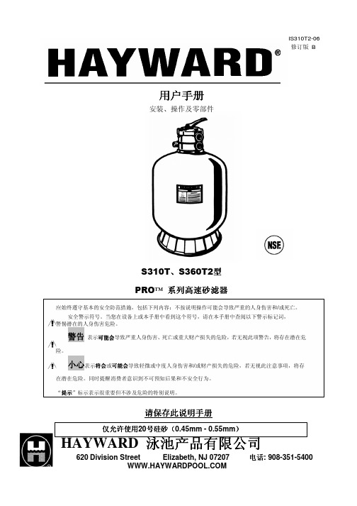
HAYWARD泳池产品有限公司S310T和S360T2型PRO
警告 – 未能保持吸水口部件无杂物,如树叶、污物、头发、纸张等物品,可能会增加吸陷的可能
性。
警告 – 泳池和温泉部件的寿命有限,盖板/网格应经常检查,最少每过十年就应更换部件,若发现部件
损坏、断裂、破裂、遗失或不牢固,也应及时更换。
小心 – 诸如过滤系统、泵、加热器等部件,应设在适当的位置,防止幼童借助这些部件进入泳池。 警告 – 切勿在压力高于40 PSI的情况下运行或测试循环系统。 小心 – 所有的电气连接必须由具有资质的专业人员完成,必须遵循地方规程和法规。 警告 – 切勿在泵运行期间变更过滤器控制阀的位置。
用户手册
安装、操作及零部件
IS310T2-06 修订版 B
S310T、S360T2型 PRO™ 系列高速砂滤器
应始终遵守基本的安全防范措施,包括下列内容:不按说明操作可能会导致严重的人身伤害和/或死亡。 安全警示符号。当您在设备上或本手册中看到这个符号,请在本手册中查阅以下警示标记词,
警惕潜在的人身伤害危险。
排污—可绕开过滤器直接泄污,降低水位,清空大 块堵塞物。 再循环—水流可以绕过过滤器在泳池系统中实现 再循环。 关闭—将水流从水泵切换到过滤器。 清空—清空可以在过滤器内直接进行。当清空大块 堵塞物时,可将阀门拨到“排污”,绕开过滤器, 直接排污。
防冻
6. 过滤器清空后记下压强计的首次显示数据。(因水泵和 管道系统情况不同,泳池与泳池之间的该数字也不尽相同)。 由于过滤器过滤出池水中的污垢和杂质,随着它们量的积 累,过滤器内的压力会上升,流量会减少。当压强计显示值 比初始记录的“干净”数值高 8-10 磅/平方英寸磅/平方英 寸(即 0.55-0.69 条纹处)时,则要反冲洗过滤器。(详见 过滤器控制阀门功能下的反冲洗)
海沃德泳池产品手册说明书
HAYWARD POOL PRODUCTS - 620 Division Street - Elizabeth - NJ 07201 - USA
••
WARNING: Electrical Hazard. Failure to follow instructions can result in serious injury or death.
objects away from openings and moving parts.
• WARNING – Motor must be suitably grounded. Connect ground wire to green grounding screw and for cord connected
persons in order to avoid a hazard.
• WARNING – For disconnection from main power supply an external switch having a contact separation in all poles that
• WARNING – Use Only Genuine Hayward Replacement Parts.
• WARNING – If the supply cord is damaged it must be replaced by the manufacturer, service agent, or similarly qualified
IS2800X5W - Rev D
owner’s manual GUIDE DE L’UTILISATEUR
游泳池设备操作说明书
游泳池设备操作说明书一、引言游泳池是人们休闲娱乐的好去处,为了保证游泳池的正常运行和游泳者的安全,正确操作游泳池设备非常重要。
本操作说明书将详细介绍游泳池设备的操作方法和注意事项。
二、设备概述游泳池设备主要包括:过滤系统、消毒系统、循环系统和照明系统。
以下将介绍各个系统的操作方法。
1. 过滤系统过滤系统是游泳池水质保持清洁的关键。
以下是过滤系统的操作步骤:a. 打开过滤系统主电源。
b. 检查过滤器的工作状态,确保无堵塞或泄漏。
c. 若过滤器需要清洗,关闭进水阀,打开排水阀,清洗过滤器,并确保清洗完毕后关闭排水阀。
d. 按照设备规定的操作频率,定期更换过滤器。
2. 消毒系统消毒系统可以保证游泳池水中的细菌和病毒得到有效的消灭。
以下是消毒系统的操作步骤:a. 打开消毒系统主电源。
b. 检查消毒设备的工作状态和消毒剂储罐的液位。
c. 若消毒剂储罐需要补充消毒剂,按照规定的浓度和方法进行添加。
d. 定期检查消毒设备的运行情况,确保消毒效果正常。
3. 循环系统循环系统能够保持游泳池水的流动和循环,以避免死水区的产生。
以下是循环系统的操作步骤:a. 打开循环系统主电源。
b. 检查循环泵的运行情况,确保循环泵正常工作。
c. 定期检查循环管道的连接情况,确保无漏水或堵塞。
4. 照明系统照明系统提供游泳池的照明和美观效果。
以下是照明系统的操作步骤:a. 打开照明系统主电源。
b. 检查照明设备的工作状态,确保灯泡亮度正常。
c. 定期清洁照明设备,以保证良好的照明效果。
三、注意事项在操作游泳池设备时,务必注意以下几点以确保操作的顺利和安全:1. 严禁擅自拆卸、修理设备,若发现设备出现故障,请及时联系专业维修人员进行处理。
2. 注意设备的工作环境温度,避免过高或过低温度对设备造成损坏。
3. 定期检查和清洁设备,避免设备堵塞或损坏。
4. 遵循设备使用说明书,按照规定的方法和频率进行操作和维护。
5. 如发生紧急情况或设备故障,应立即切断设备电源,并采取相应的应急措施。
- 1、下载文档前请自行甄别文档内容的完整性,平台不提供额外的编辑、内容补充、找答案等附加服务。
- 2、"仅部分预览"的文档,不可在线预览部分如存在完整性等问题,可反馈申请退款(可完整预览的文档不适用该条件!)。
- 3、如文档侵犯您的权益,请联系客服反馈,我们会尽快为您处理(人工客服工作时间:9:00-18:30)。
泳池系统使用说明书泳池系统安装设备有:滨特尔循环水泵、蓝白投药泵、TRIOGEN臭氧系统、CHEMTROL水质监控仪、南华板式热交换器等主要组成。
一、滨特尔循环水泵(一)产品信息7、按照美国国家电气规程将电机安装到泳池设施上。
使用AWG 8 号或更大线号的实心铜导线。
将导线从外部连接部分接至泳池设施,参见图1。
8、将水泵永久性接到电路上。
确保该电路上无其它灯具和电气设备。
(二)维护如果水泵不能注水,或者水泵已经在滤网无水条件下运行,不得打开滤网。
A.水泵篮状滤网清洗程序。
1、关闭电机。
2、释放系统压力。
3、按逆时针方向旋转夹具和泵盖,直至转不动为止。
4、转动夹具和泵盖,拆下夹具和泵盖。
5、将篮状滤网内的碎屑收集到垃圾箱,然后冲洗滤网。
如果滤篮破裂,应进行更换。
6、装回滤篮,并向泵壳和涡壳和进水口注水。
7、清洗机盖、机盖O 形圈以及水泵室(pot)的密封面。
用特氟隆或硅基润滑剂润滑O 形圈。
8、把夹具和泵盖安装到到泵室上,将盖子重新装回,参见图2。
a.确保罩盖O 形圈位置放置正确。
将夹具安放好,然后按顺时针方向旋转,直至把手水平为止,参见图3。
9、将断路器上的电源旋转至"ON"(接通)。
将泳池时钟重新设置正确时间。
10、打开过滤器顶部的High Flow TM手动放气阀。
11、远离过滤器。
启动水泵。
12、释放过滤器内的空气,直至有稳定的水流流出。
关闭High Flow TM手动放气阀。
B. 冬季防冻。
1、如果气温降低到35°F,水泵内的水将会结冰,对设备造成损坏。
因结冰造成设备的损坏不在质量保证范围之内。
2、为防止结冰导致设备损坏,请按照以下程序进行操作:a.关闭断路器水泵电源。
b.取下水泵壳体上的两个排水旋塞,排空水泵壳体内的水。
放好水泵滤篮内的插塞。
c.遮盖电机,以防止雨雪天气造成电机损坏。
d.不得以塑料材料遮盖电机。
I否则将在电机内部形成结露并引起锈蚀。
c.电机注意事项。
1.远离热源。
a.将电机置于阴凉处,避免阳光直射。
b.保持电机外壳通风良好,防止过热。
c.提供充分的对流通风。
2.防止灰尘进入。
a.防止异物进入或溅水。
b.切勿在靠近电机的地方存放(或倾倒)泳池用化学药品。
c.电机运行时,避免在电机附近清扫或搅起灰尘。
d.如果电机因为灰尘或污垢造成损坏,质量保证无效。
3.防止电机受潮。
a.保护电机,防止泳池溅水。
b.保护电机,防止受天气影响。
c.保护电机,防止草坪喷灌机溅水。
d.如果电机潮湿,在运行前须将电机弄干。
如果电机被淹,切勿运行水泵。
e.如果电机被水损坏,质量保证无效。
注意不得用塑料或其它不透气的材料遮盖电机。
在暴风雨期间、冬季贮藏等情况下可以遮盖电机,但在电机运行或者即将运行时,不得遮盖电机。
注意更换电机时,确保电机支架位置正确,并和要安装的电机尺寸相匹配。
(三)产品操作A、如果水泵安装位置位于泳池水位面以下,在打开水泵上的毛发过滤器之前,要关闭回水管和吸入管线。
确保操作之前,重新打开阀门。
以这种方式连续运行水泵将导致压力下降,并损坏泵壳体、叶轮和密封件。
B. 水泵注水。
1. 在水泵开始启动时,必须将水泵滤网内充满水。
按照以下步骤为水泵注水:a. 拆下水泵泵盖塑料夹具,拆下水泵泵盖。
b. 向泵滤网(strainer pot)内注满水。
c. 将泵盖和塑料夹具重新装配到滤网上。
这时可以开始为水泵注水。
d. 打开过滤器上的放气阀,远离过滤器。
e. 打开开关或定时时钟。
f. 当有水从放气阀流出时,关闭放气阀。
系统中空气已经排除,并开始循环泳池水。
2. 对于双速泵:a. 水泵应该在高速下运行,以便注水。
b. 注水完成之前,水泵运行时间不得超过8 分钟。
二、蓝白投药泵(一)、安装选择离药桶较近的地方,并把泵安装在易于维护的地方。
1、泵要安装在安全表面或墙上,使用封闭的硬件设施,在墙上安装时只能安装在表面坚固的地方,不推荐在于饰面内墙上,地脚螺丝安装。
2、使出口管道尽管的短,长管会增加管道的背压;3、不要将该泵直接安装在药水桶上,化学气味会损坏该泵,把该泵安装远离药水桶或低于药水桶液面。
4、安装该泵于药水桶液面之下,会产生重力注入药剂,这种“涌入吸水”式的安装能够减少泵的自吸时间,安装一个关闭阀、节流夹或其它装置,在维修该泵时,阻止药水的重力注入。
5、溶液桶要坚固,并盖住,以减少气味。
6、确保不能与饮水管道连接,查阅当地的管道规范。
(1)粗滤器(2)循环泵(3)循环泵(4)过滤器(5)加热器(6)止回阀(7)流量计(8)蓝白F-300 型(9)投药泵(10)蓝白C-660 型(11)溶液桶(12)注入管件(13)回水管道(二)、操作C-6601、调节泵的输出─C-660药水泵的流速可以在大约10%──100%最大输出(17:1的降速成比)的范围内的调节,它是通过凸轮机构调节的,这种机构调节泵的行程长度,在流量范围1/7内设定,系统的压力、吸程的大小和通过泵水中的液体的粘度影响泵的输出,由于这些因素,泵要选择较大规格的,选择泵的大小要选择在允许调节范围的中间值,这样比选用精确的泵更可取。
咨询生产厂家提供单个泵的曲线数据。
调节泵的输出:调节之前,确保泵已关闭。
(1)、松开蝶型螺母。
(2)、转动旋钮,使指针指向要求的设定位置。
注意:先开泵吸取少量的化学溶液,再调整。
(3)、一边握持旋钮,一边锁紧蝶型螺母,使之定位在要求的设定位置。
在泵发运前进行了测试,泵头可能有水。
2、给泵引水如果安装在较高的位置,泵的自吸更困难,因环境的压力降低,当吸管干空时,隔膜可能不能产生足够的吸力,如果发生这种现象,按以下步骤:(1)、从底阀管件上拆除排水管,灌满水。
(2)、在泵运转时,再把充满水的管子安装在底阀管件中。
(3)、当泵启动后,把脚阀放进溶夜,维护其吸水工作。
测试泵的输出——容积测试(1)、该种容积测试必须把泵的各种安装因素考虑在内,这些因素包括管道压力、液体粘度、吸程等等。
对于各泵的注射输出有最精确的测试。
(2)、确保注入管件和脚阀/ 滤嘴必须清洁和工作正常。
(3)、药水泵的安装是在正常工作条件把脚阀/ 滤嘴放进大量筒。
(4)、把量筒放满溶液,开动该泵,直到吸管中的空气全部排出,溶液进入了排水管。
(5)、若有必要,量筒添满溶液,脚阀全部浸没在溶液里,记下量筒里溶液的总量。
(6)、以一个确定的时间运转该泵,记下注射的溶液总量,测试的时间越长,结果越准确。
(三)、维护C—660药水泵告诫:当安装和维护C-660时,要穿戴合适的眼睛保护和皮肤保护用品。
1、日常检查和维护C—600药水泵需很少的维护,但是,该泵和所有的部件必须定期的检查,这对于使用该泵输送化学溶液来说特别重要。
要检查各部件有无泄露、膨胀、裂缝、变色和腐蚀的痕迹,立即更换损坏的阀的部件。
在第1周内,裂开、裂痕、变色以及类似现象是属严重的化学腐蚀现象,如果发生此类现象,要立即排出泵里的化学溶液,确定哪些零部件被腐蚀,用更合适的材料制造的零配件更换之,制造商对化学腐蚀造成的泵的损坏不承担责任。
(四)、清理C—660C—660需要经常地清理,特别是投药管件、脚阀、滤嘴和泵头阀门,清理次数要根据泵的型号和维护的严格性而定。
1、当更换隔膜时,泵头壳体和泵头盖必须清理灰尘和脏物。
2、定期清理注射/ 止回阀组件,特别当注入的液体有钙化现象时,如次氯酸钠。
这些钙化沉淀和其它的积聚物能够阻塞管件,使背压增大并影响止回阀的工作,请参见 4.3.4部分,图4.9。
3、定期清理吸水泵滤嘴图4.84、定期检查位于泵室背面和泵头下部的空气排放阀,如果需要就须清理。
三、TRIOGEN臭氧系统(一)、质量和制造标准奥宗尼亚三氧公司制造的臭氧发生器采用了现今最高标准,这包括对所提供的臭氧设备的出厂测试和过程的广泛性。
所有的生产和测试程序采用了BS5750(ISO9002)的质量控制标准,奥宗尼亚三氧公司是通过这项认证的公司。
电气元件和导线符合CSA标准(加拿大标准协会)和UL标准(保险商实验室标准导线和电气元件按照1991年第16版电气工程协会(IEE)规范。
(二)、机房工作要求1、空气质量在空气中油份和碳氢化合物的最大含量不超过5 ppm.2、空气温度/湿度奥宗尼亚三氧公司的臭氧发生器设计的设计运行温度不大于40°C。
图4.1 在25克/M3含水量的条件下温度和湿度曲线图如果空气含水分不超过25克/M3,使用图 4.1的相对湿度。
3、用电要求臭氧发生器的电源提供和水泵的接线要通过主控制板,电源的标准为:a). 415伏3相4线+地线a). 380伏3相4线+地线a). 208伏3相+地线a). 600伏3相+地线以上电源可用于50 或60 赫兹,电压公差+/- 6%功率要根据发生器的大小和频率而定。
表4.4列出了50 赫兹的电源系统中的功率消耗。
提供线路断电器与电机的启动产生的电源波动相匹配。
4、通风要求臭氧发生器的机房必须通风,循环次数每小时不小于10次。
可选择二级通风系统,在正常情况下每小时循环3次,而在紧急情况下,如臭氧泄露,循环次数每小时增加到30次。
5、冷却水要求机型M6WC 15 25 50 100 150 200 冷却水90 210 201 420 630 840升/小时(三)、臭氧发生器的安装在安装臭氧发生器时,以下各条都必须遵守。
1、臭氧发生器的位置臭氧发生器应尽可能的远离其它设备,在它们工作和运行时会发热或者带来高湿度,象加热设备、脱水机等。
在定位时,要注意留出足够的安装和维修空间。
2、电气连接臭氧发生器提供了两组标准法兰盘,它们连接发生器的主电源和控制电线的法兰盘,如图示位于发生器的顶端。
图5.2电线进入臭氧发生器3、发生器的运行因为臭氧发生器包含许多的部件,而这些部件会容易损坏。
在运行时,要格外小心。
臭氧发生器使用了专门设计的托盘包装可以使用叉车来移动,但是最终位置要靠人工来定位。
4、储水系统所有的三氧设备系列都必须装有储水系统。
管道的排列至关重要,这样才能确保发生器无故障的运行。
如图5.4所示。
该图表明了从臭氧发生器到投射加压泵的管道排列。
1-臭氧发生器2-储水器3-控制阀4-止回阀5-隔离球阀6-负压注射器7-进水隔离阀8-增压泵吸水阀9-增压泵10-增压泵出水阀11-止回阀12-静态混合器四、CHEMTROL水质监控仪一、安装安装位置的选择如图1所示,将该仪器安装在通风良好,无化学气体及阳光不可直射到的地方。
为了用电安全,该仪器必须安置与离水10英尺(3米)以上的位置。
插头电源线的标准长度是3米,若长度不够,需订购25或50英尺长的加长电源线。
连接电源如图1所示,把该仪器与主电源上的定时器连接,可防止循环泵停止运转时,投药器继续注药。
注意:安装前请检查该仪器的电压与所提供的电压是否相同。