1-Proportional-resonant controllers and filters for grid-connected voltage-source converters
Proportional & Integral Controllers

1. Set TD = 0 & TI = ∞ 2. Increase KP until the system just starts to oscillate (KP = KPO). The frequency of oscillation here is ωc and the period is TO=2π/ωc. Set controller gains as:
NB: this transfer function is non-proper and is therefore difficult to realise in practice. Proper T.F.: Strictly proper T.F.: Order N(s) ≤ Order D(s) Order N(s) < Order D(s)
Error {e(t)} t
The PID regulator is given by: Here:
KI = KP TI
1 de(t ) u (t ) = K P e(t ) + ∫ e(t )dt + TD TI dt
K D = K P TD
KI K D s 2 + K P s + K I N ( s)U (s) = KP + + KDs = = E (s) s s D( s)
Proportional & Integral Controllers Proportional + Integral (PI) controllers were developed because of the desirable property that systems with open loop transfer functions of type 1 or above have zero steady state error with respect to a step input. The PI regulator is:
LCL型并网变换器PR控制研究
Research on Proportional-resonant Controller for Grid-connected Converter with LCL-filter
学科专业:电气工程 研究生: 石立光 指导教师:万健如 教授
天津大学电气与自动化工程学院 二零一二年十二月
关键词: 关键词:并网变换器 LCL 滤波器 SVPWM 调制 二倍频分量 PR 控制器
解耦控制 正负序分解 不对称电网
ABSTRACT
With the overusing of the coal, nature gas and other fossil fuel, the human had to search for more durable, more environmental new energy to meet the increasing needs of people. It has been being widely studied that how to make full use of the generation power of solar energy, wind energy, tidal energy and other new energy power, so the grid-connected converter plays an important role in the transformation of electrical energy. The transformed power is either transmitted to electricity grid, or used to drive different loads independently. In this paper, the control policies of grid-connected converter under the symmetric grid and asymmetric grid are studied. First of all, the mathematical model of the grid-connected converter with LCL-filter is analyzed, after which the article builds respectively mathematical models of the static coordinate system and the rotating coordinate system under the symmetric and asymmetric power grid. At the same time, the positive sequence and negative sequence decomposition problem of each electric is considered under the asymmetric power grid, which adopts a modified instantaneous symmetrical component method to make an effective positive sequence and negative sequence decomposition of the grid voltage and current. The results are verified by the theoretical analysis and the simulation. Secondly, the LCL-filter parameters, including converter side inductance, power grid side inductance and the filter capacity, are designed in detail. Secondly, based on the control strategy research of grid-connected converter, this paper firstly analyzes and researches the traditional grid voltage oriented vector control strategy. Under the symmetric grid, this control strategy can be very good to meet grid standards, the access current becomes sine wave, the harmonic distortion rate is very small, as well as the grid power factor is closed to 1. Under the asymmetric grid, because there are the positive and negative sequence components in power grid voltage and access current, the dc side voltage, the active and reactive power and the dq axis component of the access current contain second harmonic frequency component during steady state operation, which seriously affects the quality of grid. Based on this, a kind of commonly used control method is double dq-PI current control strategy based on the positive and negative sequence
A Unified Control Strategy for Three-Phase Inverter

A Unified Control Strategy for Three-Phase Inverterin Distributed GenerationZeng Liu,Student Member,IEEE,Jinjun Liu,Senior Member,IEEE,and Yalin ZhaoAbstract—This paper presents a unified control strategy that en-ables both islanded and grid-tied operations of three-phase inverter in distributed generation,with no need for switching between two corresponding controllers or critical islanding detection.The pro-posed control strategy composes of an inner inductor current loop, and a novel voltage loop in the synchronous reference frame.The inverter is regulated as a current source just by the inner induc-tor current loop in grid-tied operation,and the voltage controller is automatically activated to regulate the load voltage upon the occurrence of islanding.Furthermore,the waveforms of the grid current in the grid-tied mode and the load voltage in the islanding mode are distorted under nonlinear local load with the conven-tional strategy.And this issue is addressed by proposing a unified load current feedforward in this paper.Additionally,this paper presents the detailed analysis and the parameter design of the control strategy.Finally,the effectiveness of the proposed control strategy is validated by the simulation and experimental results.Index Terms—Distributed generation(DG),islanding,load cur-rent,seamless transfer,three-phase inverter,unified control.I.I NTRODUCTIOND ISTRIBUTED generation(DG)is emerging as a viablealternative when renewable or nonconventional energy resources are available,such as wind turbines,photovoltaic ar-rays,fuel cells,microturbines[1],[3].Most of these resources are connected to the utility through power electronic interfacing converters,i.e.,three-phase inverter.Moreover,DG is a suitable form to offer high reliable electrical power supply,as it is able to operate either in the grid-tied mode or in the islanded mode[2]. In the grid-tied operation,DG deliveries power to the utility and the local critical load.Upon the occurrence of utility outage, the islanding is formed.Under this circumstance,the DG must be tripped and cease to energize the portion of utility as soon as possible according to IEEE Standard929-2000[4].However, in order to improve the power reliability of some local criticalManuscript received December15,2012;revised March4,2013;accepted April21,2013.Date of current version September18,2013.This work was supported in part by the National Basic Research Program(973Program)of China under Project2009CB219705,and by the State Key Laboratory of Elec-trical Insulation and Power Equipment under Project EIPE09109.This paper was presented in part at the26th IEEE Applied Power Electronics Conference and Exposition,Fort Worth,TX,USA,March6–11,2011.Recommended for publication by Associate Editor D.Xu.The authors are with the State Key Lab of Electrical Insulation and Power Equipment,School of Electrical Engineering,Xi’an Jiaotong Univer-sity,Xi’an710049,China(e-mail:zeng.liu@;jjliu@; yobdc54@).Color versions of one or more of thefigures in this paper are available online at .Digital Object Identifier10.1109/TPEL.2013.2262078load,the DG should disconnect to the utility and continue to feed the local critical load[5].The load voltage is key issue of these two operation modes,because it isfixed by the utility in the grid-tied operation,and formed by the DG in the islanded mode,respectively.Therefore,upon the happening of islanding, DG must take over the load voltage as soon as possible,in order to reduce the transient in the load voltage.And this issue brings a challenge for the operation of DG.Droop-based control is used widely for the power sharing of parallel inverters[11],[12],which is called as voltage mode control in this paper,and it can also be applied to DG to real-ize the power sharing between DG and utility in the grid-tied mode[13]–[16],[53].In this situation,the inverter is always regulated as a voltage source by the voltage loop,and the qual-ity of the load voltage can be guaranteed during the transition of operation modes.However,the limitation of this approach is that the dynamic performance is poor,because the bandwidth of the external power loop,realizing droop control,is much lower than the voltage loop.Moreover,the grid current is not controlled directly,and the issue of the inrush grid current dur-ing the transition from the islanded mode to the grid-tied mode always exists,even though phase-locked loop(PLL)and the virtual inductance are adopted[15].The hybrid voltage and current mode control is a popular alternative for DG,in which two distinct sets of controllers are employed[17]–[40].The inverter is controlled as a current source by one sets of a controller in the grid-tied mode,while as a voltage source by the other sets of controller in the islanded mode.As the voltage loop or current loop is just utilized in this approach,a nice dynamic performance can be achieved. Besides,the output current is directly controlled in the grid-tied mode,and the inrush grid current is almost eliminated.In the hybrid voltage and current mode control,there is a need to switch the controller when the operation mode of DG is changed.During the interval from the occurrence of utility outage and switching the controller to voltage mode,the load voltage is neitherfixed by the utility,nor regulated by the DG, and the length of the time interval is determined by the islanding detection process.Therefore,the main issue in this approach is that it makes the quality of the load voltage heavily reliant on the speed and accuracy of the islanding detection method[6]–[10]. Another issue associated with the aforementioned approaches is the waveform quality of the grid current and the load voltage under nonlinear local load.In the grid-tied mode,the output current of DG is generally desired to be pure sinusoidal[18]. When the nonlinear local load is fed,the harmonic component of the load current will fullyflow into the utility.A single-phase DG,which injects harmonic current into the utility for mitigating0885-8993©2013IEEEFig.1.Schematic diagram of the DG based on the proposed control strategy.the harmonic component of the grid current,is presented in[41]. The voltage mode control is enhanced by controlling the DG to emulate a resistance at the harmonic frequency,and then the harmonic currentflowing into utility can be mitigated[42]. In the islanded mode,the nonlinear load may distort the load voltage[43],and many control schemes have been proposed to improve the quality of the load voltage,including a multiloop control method[43]–[46],resonant controllers[48],[49],sliding mode control[47].However,existing control strategies,dealing with the nonlinear local load in DG,mainly focus on either the quality of the grid current in the grid-tied mode or the one of the load voltage in the islanded mode,and improving both of them by a unified control strategy is seldom.This paper proposes a unified control strategy that avoids the aforementioned shortcomings.First,the traditional induc-tor current loop is employed to control the three-phase inverter in DG to act as a current source with a given reference in the synchronous reference frame(SRF).Second,a novel voltage controller is presented to supply reference for the inner induc-tor current loop,where a proportional-plus-integral(PI)com-pensator and a proportional(P)compensator are employed in D-axis and Q-axis,respectively.In the grid-tied operation,the load voltage is dominated by the utility,and the voltage com-pensator in D-axis is saturated,while the output of the voltage compensator in Q-axis is forced to be zero by the PLL.There-fore,the reference of the inner current loop cannot regulated by the voltage loop,and the DG is controlled as a current source just by the inner current loop.Upon the occurrence of the grid outage,the load voltage is no more determined by the utility, and the voltage controller is automatically activated to regulate the load voltage.These happen naturally,and,thus the proposed control strategy does not need a forced switching between two distinct sets of controllers.Further,there is no need to detect the islanding quickly and accurately,and the islanding detec-tion method is no more critical in this approach.Moreover, the proposed control strategy,benefiting from just utilizing the current and voltage feedback control,endows a better dynamic performance,compared to the voltage mode control.Third,the proposed control strategy is enhanced by introduc-ing a unified load current feedforward,in order to deal with the issue caused by the nonlinear local load,and this scheme is implemented by adding the load current into the reference of the inner current loop.In the grid-tied mode,the DG injects harmonic current into the grid for compensating the harmonic component of the grid current,and thus,the harmonic compo-nent of the grid current will be mitigated.Moreover,the benefit of the proposed load current feedforward can be extended into the islanded operation mode,due to the improved quality of the load voltage.The rest of this paper is arranged as follows.Section II de-scribes the proposed unified control strategy for three-phase inverter in DG,including the power stage of DG,the basic idea, and the control diagram.The detailed operation principle of DG with the proposed control strategy is illustrated in Section III. The parameter design and small signal analysis of the proposed control system are given in Section IV.Section V investigates the proposed control strategy by simulation and experimental results.Finally,the concluding remarks are given in Section VI.II.P ROPOSED C ONTROL S TRATEGYA.Power StageThis paper presents a unified control strategy for a three-phase inverter in DG to operate in both islanded and grid-tied modes.The schematic diagram of the DG based on the proposed control strategy is shown by Fig.1.The DG is equipped with a three-phase interface inverter terminated with a LCfilter.The primary energy is converted to the electrical energy,which is then converted to dc by the front-end power converter,and the output dc voltage is regulated by it.Therefore,they can be represented by the dc voltage source V dc in Fig.1.In the ac side of inverter,the local critical load is connected directly.It should be noted that there are two switches,denoted by S u and S i,respectively,in Fig.1,and their functions are different. The inverter transfer switch S i is controlled by the DG,and the utility protection switch S u is governed by the utility.When the utility is normal,both switches S i and S u are ON,and the DG in the grid-tied mode injects power to the utility.When the utility is in fault,the switch S u is tripped by the utility instantly,and then the islanding is formed.After the islanding has been confirmed by the DG with the islanding detection scheme[6]–[10],the switch S i is disconnected,and the DG is transferred from the grid-tied mode to the islanded mode.When the utility is restored, the DG should be resynchronized with the utilityfirst,and then the switch S i is turned ON to connect the DG with the grid.Fig.2.Overall block diagram of the proposed unified control strategy.B.Basic IdeaWith the hybrid voltage and current mode control[17]–[40], the inverter is controlled as a current source to generate the reference power P DG+j Q DG in the grid-tied mode.And its output power P DG+j Q DG should be the sum of the power injected to the grid P g+j Q g and the load demand P load+ j Q load,which can be expressed as follows by assuming that the load is represented as a parallel RLC circuit:P load=32·V2mR(1)Q load=32·V2m·1ωL−ωC.(2)In(1)and(2),V m andωrepresent the amplitude and fre-quency of the load voltage,respectively.When the nonlinear local load is fed,it can still be equivalent to the parallel RLC circuit by just taking account of the fundamental component. During the time interval from the instant of islanding happen-ing to the moment of switching the control system to voltage mode control,the load voltage is neitherfixed by the utility nor regulated by the inverter,so the load voltage may drift from the normal range[6].And this phenomenon can be explained as below by the power relationship.During this time interval, the inverter is still controlled as a current source,and its output power is kept almost unchanged.However,the power injected to utility decreases to zero rapidly,and then the power consumed by the load will be imposed to the output power of DG.If both active power P g and reactive power Q g injected into the grid are positive in the grid-tied mode,then P load and Q load will increase after the islanding happens,and the amplitude and frequency of the load voltage will rise and drop,respectively,according to (1)and(2).With the previous analysis,if the output power of inverter P DG+j Q DG could be regulated to match the load demand by changing the current reference before the islanding is confirmed, the load voltage excursion will be mitigated.And this basic idea is utilized in this paper.In the proposed control strategy,the output power of the inverter is always controlled by regulating the three-phase inductor current i Labc,while the magnitude and frequency of the load voltage v C abc are monitored.When the islanding happens,the magnitude and frequency of the load volt-age may drift from the normal range,and then they are controlled to recover to the normal range automatically by regulating the output power of the inverter.C.Control SchemeFig.2describes the overall block diagram for the proposed unified control strategy,where the inductor current i Labc,the utility voltage v gabc,the load voltage v C abc,and the load current i LLabc are sensed.And the three-phase inverter is controlled in the SRF,in which,three phase variable will be represented by dc quantity.The control diagram is mainly composed by the inductor current loop,the PLL,and the current reference generation module.In the inductor current loop,the PI compensator is employed in both D-and Q-axes,and a decoupling of the cross coupling denoted byω0L f/k PW M is implemented in order to mitigate the couplings due to the inductor.The output of the inner current loop d dq ,together with the decoupling of the capacitor voltage denoted by1/k PW M,sets the reference for the standard space vector modulation that controls the switches of the three-phase inverter.It should be noted that k PW M denotes the voltage gain of the inverter,which equals to half of the dc voltage in this paper.Fig.3.Block diagram of the current reference generation module.The PLL in the proposed control strategy is based on the SRF PLL[50],[51],which is widely used in the three-phase power converter to estimate the utility frequency and phase. Furthermore,a limiter is inserted between the PI compensator G PLL and the integrator,in order to hold the frequency of the load voltage within the normal range in the islanded operation. In Fig.2,it can be found that the inductor current is regulated to follow the current reference i Lref dq,and the phase of the current is synchronized to the grid voltage v gabc.If the current reference is constant,the inverter is just controlled to be a current source,which is the same with the traditional grid-tied inverter. The new part in this paper is the current reference generation module shown in Fig.2,which regulates the current reference to guarantee the power match between the DG and the local load and enables the DG to operate in the islanded mode.Moreover, the unified load current feedforward,to deal with the nonlinear local load,is also implemented in this module.The block diagram of the proposed current reference gen-eration module is shown in Fig.3,which provides the current reference for the inner current loop in both grid-tied and islanded modes.In this module,it can be found that an unsymmetrical structure is used in D-and Q-axes.The PI compensator is adopted in D-axes,while the P compensator is employed in Q-axis.Besides,an extra limiter is added in the D-axis.More-over,the load current feedforward is implemented by adding the load current i LLdq to thefinal inductor current reference i Lref dq. The benefit brought by the unique structure in Fig.3can be rep-resented by two parts:1)seamless transfer capability without critical islanding detection;and2)power quality improvement in both grid-tied and islanded operations.The current referencei Lredq composes of four parts in D-and Q-axes respectively:1)the output of voltage controller i ref dq;2)the grid current reference I gref dq;3)the load current i LLdq;and4)the current flowing through thefilter capacitor C f.In the grid-tied mode,the load voltage v C dq is clamped by the utility.The current reference is irrelevant to the load voltage,due to the saturation of the PI compensator in D-axis,and the output of the P compensator being zero in Q-axis,and thus,the inverter operates as a current source.Upon occurrence of islanding,the voltage controller takes over automatically to control the load voltage by regulating the current reference,and the inverter acts as a voltage source to supply stable voltage to the local load; this relieves the need for switching between different control architectures.Another distinguished function of the current reference gen-eration module is the load current feedforward.The sensed load current is added as a part of the inductor current refer-ence i Lref dq to compensate the harmonic component in the grid current under nonlinear local load.In the islanded mode,the load current feedforward operates still,and the disturbance from the load current,caused by the nonlinear load,can be suppressed by the fast inner inductor current loop,and thus,the quality of the load voltage is improved.The inductor current control in Fig.2was proposed in pre-vious publications for grid-tied operation of DG[18],and the motivation of this paper is to propose a unified control strategy for DG in both grid-tied and islanded modes,which is repre-sented by the current reference generation module in Fig.3. The contribution of this module can be summarized in two as-pects.First,by introducing PI compensator and P compensator in D-axis and Q-axis respectively,the voltage controller is inac-tivated in the grid-tied mode and can be automatically activated upon occurrence of islanding.Therefore,there is no need for switching different controllers or critical islanding detection, and the quality of the load voltage during the transition from the grid-tied mode to the islanded mode can be improved.The second contribution of this module is to present the load current feedforward to deal with the issue caused by the nonlinear local load,with which,not only the waveform of the grid current in grid-tied is improved,but also the quality of the load voltage in the islanded mode is enhanced.Besides,it should be noted that a three-phase unbalanced local load cannot be fed by the DG with the proposed control strategy,because there is noflow path for the zero sequence current of the unbalanced load,and the regulation of the zero sequence current is beyond the scope of the proposed control strategy.III.O PERATION P RINCIPLE OF DGThe operation principle of DG with the proposed unified control strategy will be illustrated in detail in this section,and there are in total four states for the DG,including the grid-tied mode,transition from the grid-tied mode to the islanded mode, the islanded mode,and transition from the islanded mode to the grid-tied mode.A.Grid-Tied ModeWhen the utility is normal,the DG is controlled as a current source to supply given active and reactive power by the inductor current loop,and the active and reactive power can be given by the current reference of D-and Q-axis independently.First, the phase angle of the utility voltage is obtained by the PLL, which consists of a Park transformation expressed by(3),a PIcompensator,a limiter,and an integratorx d x q=23⎛⎜⎜⎜⎝cosθcosθ−23πcosθ+23π−sinθ−sinθ−23π−sinθ+23π⎞⎟⎟⎟⎠×⎛⎝x ax bx c⎞⎠.(3)Second,thefilter inductor current,which has been trans-formed into SRF by the Park transformation,is fed back and compared with the inductor current reference i Lref dq,and the inductor current is regulated to track the reference i Lref dq by the PI compensator G I.The reference of the inductor current loop i Lref dq seems complex and it is explained as below.It is assumed that the utility is stiff,and the three-phase utility voltage can be expressed as⎧⎪⎪⎪⎪⎪⎪⎨⎪⎪⎪⎪⎪⎪⎩v ga=V g cosθ∗v gb=V g cosθ∗−2π3v gc=V g cosθ∗+2π3(4)where V g is the magnitude of the grid voltage,andθ∗is the actual phase angle.By the Park transformation,the utility voltage is transformed into the SRF,which is shown asv gd=V g cos(θ∗−θ)v gq=V g sin(θ∗−θ).(5) v gq is regulated to zero by the PLL,so v gd equals the mag-nitude of the utility voltage V g.As thefilter capacitor voltage equals the utility voltage in the gird-tied mode,v C d equals the magnitude of the utility voltage V g,and v C q equals zero,too. In the D-axis,the inductor current reference i Lref d can be expressed by(6)according to Fig.3i Lref d=I gref d+i LLd−ω0C f·v C q.(6) Thefirst part is the output of the limiter.It is assumed that the given voltage reference V max is larger than the magnitude of the utility voltage v C d in steady state,so the PI compensator, denoted by G V D in the following part,will saturate,and the limiter outputs its upper value I gref d.The second part is the load current of D-axis i LLd,which is determined by the charac-teristic of the local load.The third part is the proportional part −ω0C f·v C q,whereω0is the rated angle frequency,and C f is the capacitance of thefilter capacitor.It isfixed as v C q de-pends on the utility voltage.Consequently,the current reference i Lref d is imposed by the given reference I gref d and the load current i LLd,and is independent of the load voltage.In the Q-axis,the inductor current reference i Lref q consists of four parts asi Lref q=v C q·k Gv q+I gref q+i LLq+ω0C f·v C d(7) where k Gv q is the parameter of the P compensator,denoted by G V Q in the following part.Thefirst part is the output of G V Q,Fig.4.Simplified block diagram of the unified control strategy when DG operates in the grid-tied mode.which is zero as the v C q has been regulated to zero by the PLL.The second part is the given current reference I gref q,and thethird part represents the load current in Q-axis.Thefinal partis the proportional part−ω0C f·v C d,which isfixed since v C d depends on the utility voltage.Therefore,the current referencei Lref q cannot be influenced by the external voltage loop and isdetermined by the given reference I gref q and the load currenti LLq.With the previous analysis,the control diagram of the invertercan be simplified as Fig.4in the grid-tied mode,and the inverteris controlled as a current source by the inductor current loopwith the inductor current reference being determined by thecurrent reference I gref dq and the load current i LLdq.In otherwords,the inductor current tracks the current reference and theload current.If the steady state error is zero,I gref dq representsthe grid current actually,and this will be analyzed in the nextsection.B.Transition From the Grid-Tied Mode to the Islanded Mode When the utility switch S u opens,the islanding happens,and the amplitude and frequency of the load voltage will drift due to the active and reactive power mismatch between the DG and the load demand.The transition,shown in Fig.5,can be divided into two time interval.Thefirst time intervals is from the instant of turning off S u to the instant of turning off S i when islanding is confirmed.The second time interval begins from the instant of turning off inverter switch S i.During thefirst time interval,the utility voltage v gabc is stillthe same with the load voltage v C abc as the switch S i is in ONstate.As the dynamic of the inductor current loop and the voltageloop is much faster than the PLL[52],while the load voltageand current are varying dramatically,the angle frequency of theFig.5.Operation sequence during the transition from the grid-tied mode to the islandedmode.Fig.6.Transient process of the voltage and current when the islanding happens.load voltage can be considered to be not varied.The dynamic process in this time interval can be described by Fig.6,and it is illustrated later.In the grid-tied mode,it is assumed that the DG injects ac-tive and reactive power into the utility,which can be expressed by (8)and (9),and that the local critical load,shown in (10),represented by a series connected RLC circuit with the lagging power factorP g =32·(v C d i gd +v C q i gq )=32v C d i gd (8)Q g =32·(v C q i gd −v C d i gq )=−32v C d i gq(9)Z s load =R s +jωL s +1jωC s=R s +j ωL s −1ωC s=R s +jX s .(10)When islanding happens,i gd will decrease from positive to zero,and i gq will increase from negative to zero.At the same time,the load current will vary in the opposite direction.The load voltage in D -and Q -axes is shown by (11)and (12),and each of them consists of two terms.It can be found that the load voltage in D -axis v C d will increase as both terms increase.However,the trend of the load voltage in Q -axis v C q is uncertain because the first term decreases and the second term increases,and it is not concerned for a whilev C d =i LLd ·R s −i LLq ·X s (11)v C q =i LLq ·R s +i LLd ·X s .(12)With the increase of the load voltage in D -axis v C d ,when it reaches and exceeds V max ,the input of the PI compensator G V D will become negative,so its output will decrease.Then,the output of limiter will not imposed to I gref d any longer,and the current reference i Lref d will drop.With the regulation of the inductor current loop,the load current in D -axis i LLd willdecrease.As a result,the load voltage in D -axis v C d will drop and recover to V max .After i LLd has almost fallen to the normal value,the load voltage in Q -axis v C q will drop according to (12).As v C q is decreased from zero to negative,then the input of the PI compensator G PLL will be negative,and its output will drop.In other words,the angle frequency ωwill be reduced.If it falls to the lower value of the limiter ωmin ,then the angle frequency will be fixed at ωmin .Consequently,at the end of the first time interval,the load voltage in D -axis v C d will be increased to and fixed at V max ,and the angle frequency of the load voltage ωwill drop.If it is higher than the lower value of the limiter ωmin ,the PLL can still operate normally,and the load voltage in Q -axis v C q will be zero.Otherwise,if it is fixed at ωmin ,the load voltage in Q -axis v C q will be negative.As the absolute values of v C d and v C q ,at least the one of v C d ,are raised,the magnitude of the load voltage will increase finally.The variation of the amplitude and frequency in the load volt-age can also be explained by the power relationship mentioned before.When the islanding happens,the local load must ab-sorb the extra power injected to the grid,as the output power of inverter is not changed instantaneously.According to (1),the magnitude of the load voltage V m will rise with the increase of P load .At the same time,the angle frequency ωshould drop,in order to consume more reactive power with (2).Therefore,the result through the power relationship coincides with the previ-ous analysis.The second time interval of the transition begins from the instant when the switch S i is open after the islanding has been confirmed by the islanding detection method.If the switch S i opens,the load voltage v C abc is independent with the grid volt-age v gabc .At the same time,v gabc will reduce to zero theo-retically as the switch S u has opened.Then,the input of the compensator G PLL becomes zero and the angle frequency is invariable and fixed to the value at the end of the first interval.Under this circumstance,v C dq is regulated by the voltage loop,and the inverter is controlled to be a voltage source.With the previous analysis,it can be concluded that the drift of the amplitude and frequency in the load voltage is restricted in the given range when islanding happens.And the inverter is transferred from the current source operation mode to the voltage source operation mode autonomously.In the hybrid voltage and current mode control [17]–[40],the time delay of islanding detection is critical to the drift of the frequency and magnitude in the load voltage,because the drift is worse with the increase of the delay time.However,this phenomenon is avoided in the proposed control strategy.C.Islanded ModeIn the islanded mode,switching S i and S u are both in OFF state.The PLL cannot track the utility voltage normally,and the angle frequency is fixed.In this situation,the DG is controlled as a voltage source,because voltage compensator G V D and G V Q can regulate the load voltage v C dq .The voltage references in D -and Q -axis are V max and zero,respectively.And the magnitude of the load voltage equals to V max approximately,which will。
适用于电网三相不平衡的光伏逆变器控制策略设计

态遥
因此袁 本文所设计策略能很好地应对电网电压不
对称的情况袁 且系统的电流控制快速性较好袁 充分证
明了本文方案的正确性遥
4 结论
本文针对常规光伏逆变器在不平衡电网情况下的 正常运行受影响问题袁提出了改进的控制策略遥
渊 1 冤 设 计 了 基 于 SOGI 的 不 平 衡 锁 相 环 袁 可 快 速 且 准确的锁定电网相位曰
D
(
s
)
=
v' v
=
k棕's s 2 + k棕's + 棕' 2
渊9冤
Q
(s
)
=
qv' v
=
s
2
k棕's + k棕's + 棕' 2
渊 10 冤
式 中 袁 v 为 输 入 的 正 弦 信 号 袁 棕' 是 滤 波 器 中 心 频
率袁k 是阻尼系数袁常取为 姨2 遥
3
图 4 正尧负序双同步坐标系控制框图
如下院
v abc
=v
+ abc
+v
abc
+
v
0 abc
渊1冤
v+ abc
= T + vabc =
1 3
1杉山
山
山
a山
山
2山Βιβλιοθήκη 山山a山删山
a
a v 2
煽衫 衫
杉山
衫山
a
煽衫 衫
1
a v 衫 山
衫
衫山
衫
衫山 衫山
b
衫 衫
a2
a v 衫 山
衫
quasi-proportional-resonant翻译

quasi-proportional-resonant翻译"Quasi-proportional-resonant"的翻译是"准比例谐振"。
这个术语是用来描述控制系统中一种特殊的控制策略。
在准比例谐振控制中,控制系统的输入信号通过一个准比例谐振滤波器进行滤波处理,以提取出特定频率范围内的信号。
这种控制策略常用于工程中的振动控制、噪声抑制和多频谐振控制等应用领域。
以下是12个使用准比例谐振控制相关词汇和双语例句:1. Quasi-proportional-resonant controller:准比例谐振控制器Example: The quasi-proportional-resonant controller effectively suppresses the vibrations in the system.2. Resonance frequency:谐振频率Example: The resonance frequency of the system can be tuned using a quasi-proportional-resonant filter.3. Control strategy:控制策略Example: The quasi-proportional-resonant control strategy provides better performance compared to traditional control methods.4. Vibration control:振动控制Example: The quasi-proportional-resonant technique is widely used for vibration control in mechanical systems.5. Noise suppression:噪声抑制Example: The quasi-proportional-resonant approach effectively suppresses noise for improved signal quality.6. Multi-frequency resonance control:多频谐振控制Example: The quasi-proportional-resonant method allowsfor simultaneous control of multiple resonance frequencies.7. Filtering:滤波处理Example: The quasi-proportional-resonant filter removes unwanted frequency components from the input signal.8. Frequency range:频率范围Example: The quasi-proportional-resonant technique focuses on a specific frequency range for optimal control.9. System stability:系统稳定性Example: The quasi-proportional-resonant control ensures system stability even under varying operating conditions.10. Harmonic suppression:谐波抑制Example: The quasi-proportional-resonant algorithm effectively suppresses harmonic distortions for improved power quality.11. Adaptive control:自适应控制Example: The quasi-proportional-resonant approach allows for adaptive control based on real-time system conditions.12. Control performance:控制性能Example: The quasi-proportional-resonant technique improves the control performance of the system by reducing unwanted vibrations.。
四桥臂有源滤波器在静止坐标系下的改进PR控制 (1)
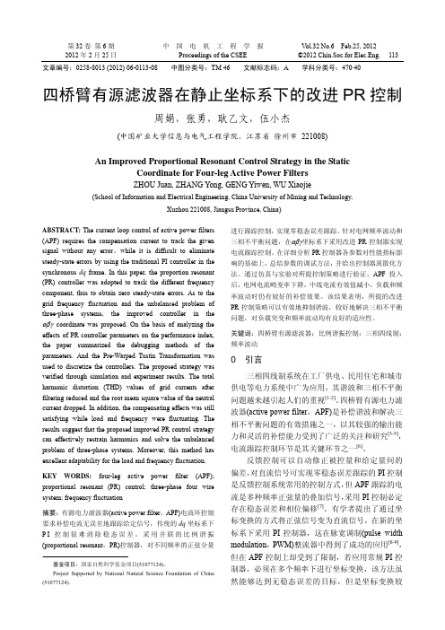
第32卷第6期中国电机工程学报V ol.32 No.6 Feb.25, 20122012年2月25日Proceedings of the CSEE ©2012 Chin.Soc.for Elec.Eng. 113 文章编号:0258-8013 (2012) 06-0113-08 中图分类号:TM 46 文献标志码:A 学科分类号:470⋅40四桥臂有源滤波器在静止坐标系下的改进PR控制周娟,张勇,耿乙文,伍小杰(中国矿业大学信息与电气工程学院,江苏省徐州市 221008)An Improved Proportional Resonant Control Strategy in the StaticCoordinate for Four-leg Active Power FiltersZHOU Juan, ZHANG Yong, GENG Yiwen, WU Xiaojie(School of Information and Electrical Engineering, China University of Mining and Technology,Xuzhou 221008, Jiangsu Province, China)ABSTRACT: The current loop control of active power filters (APF) requires the compensation current to track the given signal without any error,while it is difficult to eliminate steady-state errors by using the traditional PI controller in the synchronous dq frame. In this paper, the proportion resonant (PR) controller was adopted to track the different frequency component, thus to obtain zero steady-state errors. As to the grid frequency fluctuation and the unbalanced problem of three-phase systems, the improved controller in the αβγ coordinate was proposed. On the basis of analyzing the effects of PR controller parameters on the performance index, the paper summarized the debugging methods of the parameters. And the Pre-Warped Tustin Transformation was used to discretize the controllers. The proposed strategy was verified through simulation and experiment results. The total harmonic distortion (THD) values of grid currents after filtering reduced and the root mean square value of the neutral current dropped. In addition, the compensating effects was still satisfying while load and frequency were fluctuating. The results suggest that the proposed improved PR control strategy can effectively restrain harmonics and solve the unbalanced problem of three-phase systems. Moreover, this method has excellent adaptability for the load and frequency fluctuation.KEY WORDS: four-leg active power filter (APF); proportional resonant (PR) control; three-phase four wire system; frequency fluctuation摘要:有源电力滤波器(active power filter,APF)电流环控制要求补偿电流无误差地跟踪给定信号,传统的dq坐标系下P I控制很难消除稳态误差。
Proportional
Proportional-Resonant Current Control of Single-Phase Grid-TiedPV Inverter SystemSu Xiu’e, B. Author2, and C. Author3Abstract—In this paper, a proportional resonant (PR) control scheme is proposed for single-phase grid-tied boost-buck PV inverter to achieve high-quality sinusoidal output currents. Simulation results are provided to illustrate the effectiveness of the proposed scheme.Index terms—PR (Proportional-Resonant) Control, Single-phase, PV System.Ⅰ IntroductionCurrent distortion is an important performance index for grid connected PV inverters. Low THD of output current requires accurate current control scheme. Resonant controller which is based on internal model principle is found to be zero steady-state tracking error control scheme for sinusoidal signals [1] -[3].This paper proposes a proportional resonant (PR) control scheme for single-phase grid-tied boost-buck inverter to achieve high-quality sinusoidal output currents. Simulation results are provided to illustrate the effectiveness of the proposed scheme.Ⅱ Boost-Buck PV Inverter and Proposed PR Control SchemeFig.1 shows the total structure of the grid-tied inverter of the PV system discussed in this paper.Fig.1 the total structure of the PV systemFig.1 gives a boost-buck PV inverter system, which contains a DC-DC boost converter and a H-bridge inverter. The function of the DC-DC boost converter is to regulate the output current to track maximum power point (MPP) of the PV panel, while the inverter is used to achieve high quality sinusoidal output current and maintain constant dc link voltage.A. Control Scheme of DC-DC ConverterAs all known that the output power of PV arrays is always changing with weather conditions, i.e., solar irradiation and atmospheric temperature. Therefore, real time MPPT control for extracting maximum power from the PV arrays becomes indispensable in PV generation systems [6][7]. There are many methods, e.g., Perturb and Observe (P&O) [9], Incremental Conductance (INC) [8][9], Constant Voltage (CV) and others [9]. Comparing all the methods we choose the INC to implement the MPPT in our system. And the flowchart of the INC MPPT method is shown in Fig.2.Fig.2 the flowchart of the INC Fig.3 the structure of DC-DC converterThe electrical dynamics of the DC-DC converter is shown in Fig.3[4], assuming continuous conduction mode of operation, the state space averaging model will be given in the following equation,()1Lpv dc di LU D U dt=-- (1) where D is the duty cycle.B. PV Inverter and The PR ControllerThe electrical dynamics of the grid-tied inverter as shown in Fig.1 can be described as follows:acAB ac ac di u Li R u dt=++ (2) We can check the u ac and i ac , respectively, but the object of the inverter is to achieve high-quality sinusoidal output currents, so many literatures adopt the current tracking directly, e.g. DB(deadbeat), PI, RP(repetitive proportion) and so on, but a proportional resonant (PR) control scheme is proposed in this paper.As shown in Fig.1, the grid-tied inverter adopts the double-loop control, voltage loop and current loop. The PI controller is used to control the voltage U dc , while the PR controller is adopted to control the current i ac .The transfer function of the PR is described as follows [1],()2222s r c s c Y K s G s E s s ωωω==++ (4) The rational function in (4) can be rewritten as:()()()()2122i c c Y s K E s Y s Y s s s ωωω⎡⎤=--⎢⎥⎣⎦(6)Equation (6) can be represented by the control block representation shown in Fig.4. From this Figure, it can be deduced that the resonant function can be physically implemented using op-amp integrator and inverting/non-inverting gain amplifiers.Fig.4 Decomposition of resonant block into two interlink integratorsThen we analyze the characters of the PR control in frequency domain. The magnitude-frequency characteristic of the PR is described like that:A = (5) And the A is now infinite, so the PR control could implement zero steady-state errors tracking. Ⅲ Simulation ResultsSampling frequency Switching frequency Grid- frequency Boost inductor Boost capacitor Grid-tied inductor AC voltage (RMS) DC reference voltage10kHz 10kHz 50Hz 1mH3000 F μ10mH 220V 400VTable.1 System parameters Open voltage Short currentMaximum power point voltage Maximum power point current Maximum power225V 8A175V 7.15A1251.25W Atmospheric temperature Solar irradiation 25o C1000W/m 225o C600W/m 2203.5V 4.8A679.107W 158.3V 4.29ASolar output capacitor1000 Fμ1000 FμTable.2 PV arrays parametersKey parameters of the system are listed in Table.1, and table.2 shows the PV arrays parameters. As shown in Fig.5 b.) simulation results demonstrate that the MPPT is achieved within certain accuracy under varying solar irradiation. It costs 0.4s to achieve the MPP at begin, and when the solar irradiation changes from 1000W/m 2 to 600W/m 2 at 1.5s, the MPP is tracked in 0.1s. Fig.5 a.) shows the voltage of DC-link which tracks the reference voltage based on the PI control scheme [2], similar with the MPP, it tracks the reference after 0.6s, and when the solar irradiation changes at 1.5s it takes 0.5s to follow the reference again.time/sU d cI p vU p va.)factor is nearly unity.The grid-tied current is the inductance-current is 2.60% as shown in Fig.6b.).time/sU a c /VUac-Iactime/sI a c /AFrequency (Hz)M a g (% o f F u n d a m e n t a l )a.)b.)Fig.6 Simulation results of the inverter, a.) the grid-voltage and inductance-current, b.) the THD of the inductance-current.With the above-mentioned the solar irradiation changes from 1000W/m 2 to 600W/m 2 at 1.5s, so the MPP is changed, the power falls from 1251.25W to 679.107W, and the inductance-current moves from 8.05A(amplitude) to 4.37A as shown in Fig.5 a.). Ⅳ ConclusionsThis paper presents a proportional resonant (PR) control scheme for single-phase grid-tied inverter to achieve high-quality sinusoidal output currents. The system is simple in structure because there is less relation between the two stages (boost and inverter). And the PR is designed to enhance the converter reference tracking performance and alleviate steady-state errors in single-phase systems.Another advantage associated with the PR controllers is the possibility of implementing selective harmonic compensation without requiring excessive computational resources. The effectiveness of the proposed scheme is illustrated by the simulation results provided in this paper.The proposed method can also be introduced to three-phase applications without coordinate transformation. Based on the similar control theory, PR can also be used in an active power filter.Reference[1]R. Teodorescu, F. Blaabjerg, M. Liserre, P.C. Loh, “Proportional-resonant controllers and filtersfor grid-connected voltage-source converters,” IEE Proceedings on The Institution of Engineering and Technology, pp: 750-762, No.20060008.[2]J. Selvaraj, N.A. Rahim, C. Krismadinata, “Digital PI Current Control for Grid Connected PVInverter,” IEEE Trans. on Power Electronics, pp: 742-746, 2008.[3]G.P. Liua, S. Daleyb, “Optimal-tuning PID control for industrial systems,” Control EngineeringPractice, pp: 1185–1194, 9 (2001).[4]J. Mahdavi, A. Emadi, H.A. Toliyat, “Application of State Space Averaging Method to SlidingMode Control of PWM DC DC Co nverters,” IEEE Industry Applications Society Annual Meeting, pp.820-827, October, 1997.[5]Atsuo KAWAMURA, Tomoki YOKOYAMA, “Comparison of Five Different Approaches forReal Time Digital Feedback Control of PWM Inverters,” IEEE Industry Applications Society Annual Meeting, pp: 1005-1011, Oct, 1990.[6]Trishan Esram, Patrick L. Chapman, “Comparison of Photovoltaic Array Maximum Power PointTracking Techniques,” IEEE Trans. on Energy Conversion, Vol.22, No.2, pp.439-449, June 2007.[7]G.M.S. Azevedo, M.C. Cavalcanti, K.C. Oliveira, “Evaluation of Maximum Power PointTracking Methods for Grid Connected Photovoltaic Systems,” IEEE Power Electronics Specialists Conference, June, 2008, pp: 1456-1462.[8]Fangrui Liu, Shanxu Duan, Fei Liu, Bangyin Liu, “A Variable Step Size IN C MPPT Method forPV Systems,” IEEE Transactions on industrial Electronics, Vol.55, No.7, pp: 3622-3628, July, 2008.[9]Trishan Esram, Patrick L. Chapman, “Comparison of Photovoltaic Array Maximum Power PointTracking Techniques,” IEEE Trans. on Energy Conver sion, Vol.22, No.2, pp.439-449, June 2007.。
基于PR控制的三相并网逆变器研究_刘超厚
(3)
其中,Clark 变换矩阵为:
1 1 1 − − 2 2 2 C32 = 3 3 3 0 − 2 2
续时间为 0.4s,对于积分控制器[0—0.2]s 输入信号为 (4) 单位阶跃信号,[0.2—0.4]s 为零,对于谐振控制器[0 —0.2]s 输入为 sin(100π t ) 正弦信号,[0.2—0.4]s 为 零,由此可以得到积分控制器和谐振控制器的输入输 出特性图分别如图 2 和图 3 所示。
参考文献
图 10 准 PR 控制并网电流频谱 [1] Mateus Active F. And Schonardie Reactive and Power Denizar Control C. Martins. dq0 “Three-Phase Grid-Connected Photovoltaic System With Using Transformation,” PESC 2008 Rhodes, pp.1202-1207. [2] R.Teodorescu, F.Blaabjerg, M.Liserre and P.C.Loh. “Proportional-resonant grid-connected controllers and filters for voltage-source converters,”IEE
1.引言
在三相并网逆变器中,电流控制的传统控制方法 是将控制量转换到旋转坐标系下, 然后分别对 d 、 q轴 分量采用 PI 控制,因为在三相旋转坐标系下 d 、 q 轴 分量表现为直流量,而积分器对直流分量有无穷大的 增益,因此可以实现系统无稳态误差控制。然而在三 相并网逆变器中采用旋转坐标系下的 PI 控制要经过 Clark 和 Park 变换,而且 d 、 q 轴分量存在耦合,为 了达到良好的控制效果需要进行解耦控制[1],在实现 中由于解耦不精确会对控制效果产生一定的影响。本 文介绍了一种谐振控制算法, 不需要繁琐的坐标变换, 并且不需要进行解耦控制,可以达到良好的控制效果 [2] 。
三相四线制有源电力滤波器指定次数谐波控制策略
三相四线制有源电力滤波器指定次数谐波控制策略李彩林;惠梓舟;蔡儒军;周志林【摘要】针对三相四线制低压配电网不平衡非线性负载的电能质量问题,提出采用矢量谐振控制器对电容分离型有源电力滤波器(Active Power Filter,APF)进行指定次数谐波控制方案.在αβγ坐标系下对电容分离型APF进行建模,省去了在dq坐标系下的电流交叉解耦环节.比例谐振控制器应用在APF闭环控制系统时,存在各次谐振点附近谐振尖峰影响闭环控制系统稳定性和补偿精度的问题,采用矢量谐振控制器实现指定次数谐波跟踪控制,其分子零点与控制对象的极点抵消,实现控制系统降阶,提高了控制性能.仿真结果表明,所提控制方法在针对指定次数谐波补偿方面有着良好效果,其三相不平衡被抑制,直流侧电容电压得到均衡控制,证明了所提方法有效性.%In view of the power quality of unbalanced nonlinear load for the three-phase four wire low voltage distribu-tion network, the control scheme of using vector proportional resonant controller to suppress specific harmonic is pro-posed.The split-capacitor-type active power filter ( APF) mathematical model is established based onαβγcoordinate system, and current cross decoupling link under dq coordinate system is omitted.The proportional resonant controller is applied in the closed-loop control system of APF, and the resonance peak near the resonance point can affect the stability and compensation precision.In this paper, the vector resonance controller is adopted to suppress specific har-monic tracking control, and the zero point of the controller can molecule the pole of control object, thus the three-phase unbalanced order of control system is reduced to improve the control performance, and the DC side capacitorvoltage is also controlled in balance.The simulation results verify the validity of the proposed method.【期刊名称】《电测与仪表》【年(卷),期】2017(054)003【总页数】6页(P83-88)【关键词】电容分离型;有源电力滤波器;不平衡;指定次数谐波控制;矢量谐振控制器【作者】李彩林;惠梓舟;蔡儒军;周志林【作者单位】桂林电子科技大学机电工程学院,广西桂林541004;桂林电子科技大学机电工程学院,广西桂林541004;桂林电子科技大学机电工程学院,广西桂林541004;桂林电子科技大学机电工程学院,广西桂林541004【正文语种】中文【中图分类】TM7140 引言随着电力电子技术的不断发展,大量非线性负载被广泛运用于低压配电网中,不平衡、谐波和无功问题日益突出,同时由于中性线的存在,零序电流的补偿也成了一个研究的热点[1]。
探讨适配器电源设计并结合FAN6921芯片介绍
设计进行理论计算,确定最大应力值,再根据实际测试的结果来最终选定功率器件的电压和电流等规格的参数。
电气性能调试整个电源第一次装上元件后,可以先按功能块来分别调试,每部分功能都调试好后,再合在一起测试性能.如PFC部分,DC-DC部分,辅助电源,保护电路等。
需要测试的内容有:电源的输出电压调整率,电压纹波,电源保护功能等,检验电感是否饱和,主要开关管的最大应力和温度是否有足够余量。
安全验证接下来,就可进行产品安全方面的测试和验证了,如电磁干扰测试,温升测试(主要开关管,电感,变压器,电容的最大工作温度是否在其规格范围内);产品安全性测试,如雷击测试,绝缘耐压测试,电源老化实验,抗静电测试等,最后还要计算整个电源的平均失效时间等;设计流程步骤-1: 确定系统规格通过以上的介绍后,大家会对电源的设计步骤有了一个简单的了解。
下面用一个120W 的电源设计实例来进一步介绍设计过程,电源需求规格如下表:项目规格输入电压(Vin) 90~264Vac输出功率(Pout) 120W输出电压(Vout) 19V输出电流(Iout) 6.3A电压调整率<5%平均效率>87%功率因数(PF) >0.9谐波<15%安规标准IEC61000保护要求短路,过压,过功率,过温尺寸150x50x30 mm散热方式自然步骤-2: 选择电源结构电源功率范围选择可以选择反激或半桥结构,如果成本压力大的话,用反激式DC/DC 的结构是不错的选择。
步骤-3: 选择PFC和DC/DC 芯片因为有功率因数(简称PF)的要求,所以需要PFC芯片。
120W的电源非常适合采用电感电流临界工作模式,可选用的芯片有很多。
这里我们选用飞兆公司的FAN6961临界模式PFC 芯片。
选择DC/DC控制芯片:考虑到效率和电磁干扰及成本因素,用准谐振结构来完成直流-直流转换,可以选用飞兆的FAN6300准谐振芯片。
最近飞兆针对需要PFC的准谐振应用,推出了集成度更高的芯片FAN6921,它集成了FAN6961和FAN6300的所有功能,并增加了如输入欠压保护和过温保护,高低压输入过功率补偿等功能。
- 1、下载文档前请自行甄别文档内容的完整性,平台不提供额外的编辑、内容补充、找答案等附加服务。
- 2、"仅部分预览"的文档,不可在线预览部分如存在完整性等问题,可反馈申请退款(可完整预览的文档不适用该条件!)。
- 3、如文档侵犯您的权益,请联系客服反馈,我们会尽快为您处理(人工客服工作时间:9:00-18:30)。
Proportional-resonant controllers and filters for grid-connected voltage-source convertersR.Teodorescu,F.Blaabjerg,M.Liserre and P.C.LohAbstract:The recently introduced proportional-resonant (PR)controllers and filters,and their suitability for current/voltage control of grid-connected converters,are ing the PR controllers,the converter reference tracking performance can be enhanced and previously known shortcomings associated with conventional PI controllers can be alleviated.These shortcomings include steady-state errors in single-phase systems and the need for synchronous d –q transformation in three-phase systems.Based on similar control theory,PR filters can also be used for generating the harmonic command reference precisely in an active power filter,especially for single-phase systems,where d –q transformation theory is not directly applicable.Another advantage associated with the PR controllers and filters is the possibility of implementing selective harmonic compensation without requiring excessive computational resources.Given these advantages and the belief that PR control will find wide-ranging applications in grid-interfaced converters,PR control theory is revised in detail with a number of practical cases that have been implemented previously,described clearly to give a comprehensive reference on PR control and filtering.1IntroductionOver the years,power converters of various topologies have found wide application in numerous grid-interfaced systems,including distributed power generation with renewable energy sources (RES)like wind,hydro and solar energy,microgrid power conditioners and active power filters.Most of these systems include a grid-connected voltage-source converter whose functionality is to synchro-nise and transfer the variable produced power over to the grid.Another feature of the adopted converter is that it is usually pulse-width modulated (PWM)at a high switching frequency and is either current-or voltage-controlled using a selected linear or nonlinear control algorithm.The deciding criterion when selecting the appropriate control scheme usually involves an optimal tradeoff between cost,complexity and waveform quality needed for meeting (for example)new power quality standards for distributed generation in low-voltage grids,like IEEE-1547in the USA and IEC61727in Europe at a commercially favour-able cost.With the above-mentioned objective in view while evaluating previously reported control schemes,the general conclusion is that most controllers with precise reference tracking are either overburdened by complex computationalrequirements or have high parametric sensitivity (sometimes both).On the other hand,simple linear proportional–integral (PI)controllers are prone to known drawbacks,including the presenceof steady-state error in the stationary frame and the need to decouple phase dependency in three-phase systems although they are relatively easy to imple-ment [1].Exploring the simplicity of PI controllers and toimprove their overall performance,many variations have been proposed in the literature including the addition of a grid voltage feedforward path,multiple-state feedback and increasing the proportional gain.Generally,these variations can expand the PI controller bandwidth but,unfortunately,they also push the systems towards their stability limits.Another disadvantage associated with the modified PIcontrollers is the possibility of distorting the line current caused by background harmonics introduced along the feedforward path if the grid voltage is distorted.This distortion can in turn trigger LC resonance especially when a LCL filter is used at the converter AC output for filtering switching current ripple [2,3].Alternatively,for three-phase systems,synchronous frame PI control with voltage feedforward can be used,but it usually requires multiple frame transformations,and can be difficult to implement using a low-cost fixed-point digital signal processor (DSP).Overcoming the computa-tional burden and still achieving virtually similar frequency response characteristics as a synchronous frame PI [6].With the introducedE-mail:fbl@iet.aau.dkR.Teodorescu and F.Blaabjerg are with the Drives,Institute of Energy Technology,straede 101,9220Aalborg East,DenmarkM.Liserre is with the Department of Engineering,Polytechnic of Bari,70125-Bari,P.C.Loh is with the School of Electrical and Technological University,Nanyang Avenue,r The Institution of Engineering and IEE Proceedings online no.20060008doi:10.1049/ip-epa:20060008Paper first received 10th January and in PI 缺点改进方法丗电压前馈丆多状态反馈丆增大增益。