NHR5100单显说明书
虹润仪表5100
全量程
设定变送输出的下限量程
全量程
设定变送输出的上限量程
上限回差值(AH1) 上限输出(ON)
OFF ON ON
全量程
设定闪烁报警下限量程(测量值低于设定值时, 显示测量值并闪烁,ALG=1时有此功能) 设定闪烁报警上限量程(测量值高于设定值时, 显示测量值并闪烁,ALG=1时有此功能) 设定光柱显示的下限量程值(光柱表时有用) (见仪表参数说明5) 设定光柱显示的上限量程值(光柱表时有用) (见仪表参数说明5) 设定输入信号的测量下限量程
下限输出(ON)
ON
OFF
全量程
下限设定值(AL2)
上限设定值(AL1)
全量程
★位式上限报警输出: ★位式下限报警输出:
全量程
上限报警设定值
下限报警设定值
全量程
OFF
ON
OFF
ON
ON OFF
ON OFF
全量程
设定输入信号的测量上限量程
0~100%
LOC 0 AL1 400
-1-
参数 LoC 设定参数禁锁 AL1 第一报警值
设定范围 LoC=00 LoC≠00,132 LoC=132 -1999~9999
说 明 无禁锁(一级参数可修改) 禁 锁(一级参数不可修改) 无禁锁(一级参数、二级参数可修改) 第一报警的报警设定值
七、参数说明 1.报警输出(AL1、AL2、AH1、AH2) ★关于回差: 本仪表采用报警输出带回差,以防止输出继电器在或报警输出临界点上下波动时频繁动作。 具体输出状态如下: ★测量值由低上升时: ★测量值由高下降时 : 下限回差值(AH2)
6.2二级参数设置 在工作状态下,按压 键PV显示LOC,SV显示参数数值:按 或 键来进行设置,长按 键2秒可返回上一级参数, 当Loc=132时,按压 键4秒, 可进入二级参数。 二级参数如下:
nhr系列四回路数字显示控制仪使用说明书

版本号:5740-130601 NHR-5740系列四回路数字显示控制仪使用说明书一、概述NHR-5740系列四回路数字显示控制仪采用了表面贴装工艺,全自动贴片机生产,具有很强的抗干扰能力。
本仪表支持多种信号类型输入,可与各类传感器、变送器配套使用,实现对温度、压力、液位、速度、力等物理量的测量显示,可同时显示四路测量信号,可带8路分别报警输出或4路分别变送输出功能、RS485/232通讯等输出功能,适用于需要进行多测量点检测的系统。
二、技术参数输入输入信号电流电压电阻电偶输入阻抗≤250Ω≥500KΩ输入电流最大限制30mA输入电压最大限制<6V输出输出信号电流电压继电器24V配电或馈电输出时允许负载≤500Ω≥250KΩ(注:需要更高负载能力时须更换模块)AC220V/2ADC24V/2A≤30mA综合参数测量精度0.2%FS±1字设定方式面板轻触式按键数字设定;参数设定值密码锁定;设定值断电永久保存。
显示方式-1999~9999测量值显示、设定值显示,发光二级管工作状态显示使用环境环境温度:0~50℃;相对湿度:≤85%RH;避免强腐蚀气体。
工作电源AC100~240V(开关电源)(50-60HZ);DC20~29V(开关电源)。
功耗≤4W结构标准卡入式通讯采用标准MODBUS通讯协议,RS-485通讯距离可达1公里;RS-232通讯距离可达:15米。
注:仪表带通讯功能时,通讯转换器最好选用有源转换器三、仪表的面板及显示功能1外形尺寸开孔尺寸160*80mm(横式)152*76mm80*160mm(竖式)76*152mm96*96mm(方式)92*92mm 2)开机显示画面:a、显示全8,指示灯全亮:b、仪表型号和版本号:c、四路信号类型-----第1,2路输入类型-----第3,4路输入类型d、四路测量值-----第1,2路测量值-----第3,4路测量值3)面板指示灯AL1:第一报警指示灯AL2:第二报警指示灯AL3:第三报警指示灯AL4:第四报警指示灯AL5:第五报警指示灯AL6:第六报警指示灯AL7:第七报警指示灯AL8:第八报警指示灯4)操作按键确认键:数字和参数修改后的确认翻页键:参数设置下翻键退出设置键:长按2秒可返回测量画面位移键:按一次数据向左移动一位长按2秒可返回上一级参数在测量画面单击显示运算结果减少键:用于减少数值带打印功能时,显示时间增加键:用于增加数值带打印功能时,用于手动打印5)标准配线仪表在现场布线注意事项:PV输入(过程输入)1.减小电气干扰,低压直流信号和传感器输入的连线应远离强电走线。
中瀚RTK5100 Psion手簿软件操作手册

目录第一章GPS 测量概况 ........................................ 1-1§1.1 GPS接受机与卫星信号 ................................................................... 1-1 §1.2 测量技术........................................................................................... 1-2 §1.3 GPS在测量工作中的应用 ............................................................ 1-2PSION采集器................................................... 2-1§2.1简介.................................................................................................. 2-1 §2.2 PSION掌上机的结构及各部分名称 ............................................ 2-1 §2.3 电池的安装与更换......................................................................... 2-2 §2.4 键盘及其部分功能键简介............................................................. 2-3 §2.5 PSION基本用法 ............................................................................ 2-4 §2.6 交互状态下的常用命令简介........................................................... 2-6第三章PSION型控制器使用说明..................... 3-1§3.1控制器软件安装............................................................................. 3-1 §3.2具体操作步骤.................................................................................... 3-1第四章测量前的准备 ......................................... 4-1§4.1 坐标系统的确定............................................................................. 4-1 §4.2 选定测量的类型............................................................................. 4-1第五章测量步骤.................................................. 5-1§5.1控制器软件操作指南..................................................................... 5-1 §5.1.1坐标系..................................................................................... 5-2§5.1.2设置基准站............................................................................. 5-4 §5.2开始测量............................................................................................ 5-7 §5.2.1流动站的操作......................................................................... 5-7§5.2.2碎步测量................................................................................. 5-7§5.2.3 坐标库.................................................................................... 5-8§5.2.4 点放样.................................................................................. 5-11§5.2.5 解模式.................................................................................. 5-12 §5.3卫星状况.......................................................................................... 5-12 §5.3.1查看卫星信息....................................................................... 5-13§5.3.2设置卫星参数....................................................................... 5-14§5.3.3卫星删除............................................................................... 5-14§5.4工具.................................................................................................. 5-14 §5.4.1求转换参数........................................................................... 5-15§5.4.2 BL与XY间互换............................................................ 5-16§5.4.3 工程文件............................................................................ 5-16§5.4.4 软件注册............................................................................ 5-16 §5.5其他.................................................................................................. 5-16 §5.5.1基准站距离........................................................................... 5-17§5.5.2软件信息............................................................................... 5-17§5.5.3坐标浏览............................................................................... 5-17§5.5.4文件输出............................................................................... 5-18 第六章常用RTK作业方法及步骤 ................... 6-1 第七章常见问题解决办法 ................................. 7-1 附录GPS技术规格……………………………………………………….A-1第一章GPS 测量概况§1.1 GPS接收机与卫星信号卫星发送两种独特代码,第一种较为简单的代码叫C/A,第二中代码叫P码(精确)。
NHR-5100说明书
二、技术参数 备注:外形尺寸为、、的仪表继电器输出时允许负载能力为,。
版本号:5100-160112NHR -5100 系列单回路数字显示控制仪使用说明书一、产品介绍NHR -5100 系列单回路数字显示控制仪采用全自动贴片封装工艺,具有很强的抗干扰能力。
设计了双屏 LED 数码显示,显示内容更丰富。
可与各类传感器、变送器配合使用,实现对温度、压力、液位、速度、 力等物理量的测量显示,输出功能包括:报警控制、模拟变送、RS485/232 通讯等等,比传统的数显仪表还 新增加了还原出厂默认参数,操作更简便,适用更广泛。
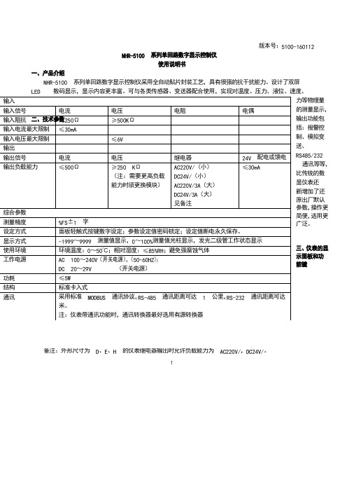
三、仪表的显示面板和功能键 输入 输入信号 电流 电压 电阻电偶输入阻抗 ≤250Ω ≥500K Ω输入电流最大限制 ≤30mA输入电压最大限制 ≤6V 输出输出信号 电流 电压继电器24V 配电或馈电 输出负载能力≤500Ω≥250 K Ω(注:需要更高负载 能力时须更换模块)AC220V/0.6(小) DC24V/0.6A (小) AC220V/3A (大) DC24V/3A (大) 见备注 ≤30mA 综合参数 测量精度 0.2%FS ±1 字设定方式 面板轻触式按键数字设定;参数设定值密码锁定;设定值断电永久保存。
显示方式 -1999~9999 测量值显示,0~100%测量值光柱显示,发光二级管工作状态显示 使用环境 环境温度:0~50℃;相对湿度:≤85%RH ;避免强腐蚀气体工作电源 AC 100~240V (开关电源),(50-60HZ ); DC 20~29V (开关电源) 功耗 ≤5W结构 标准卡入式通讯采用标准 MODBUS 通讯协议,RS -485 通讯距离可达 1 公里,RS -232 通讯距离可达 15 米。
注:仪表带通讯功能时,通讯转换器最好选用有源转换器)仪表外形尺寸及开孔尺寸:外形尺寸开孔尺寸160*80mm(横式/光柱)152*76mm80*160mm(竖式/光柱)76*152mm96*96mm(方式/光柱)92*92mm96*48mm(横式)92*45mm48*96mm(竖式)45*92mm72*72mm(方式)68*68mm48*48mm(方式)45*45mm2PV显示窗:显示测量值;在参数设定状态下,显示参数符号SV显示窗:显示输入分度号、报警值等,可根据要求自行选择显示;在参数设定状态下,显示设定参数值。
NPort 5100A 系列快速安装指南说明书

P/N: 1802051000023 *1802051000023*NPort 5100A Series Quick Installation GuideEdition 3.2, November 2018Technical Support Contact Information/supportMoxa Americas:Toll-free: 1-888-669-2872 Tel: 1-714-528-6777 Fax: 1-714-528-6778 Moxa China (Shanghai office): Toll-free: 800-820-5036 Tel: +86-21-5258-9955 Fax: +86-21-5258-5505 Moxa Europe:Tel: +49-89-3 70 03 99-0 Fax: +49-89-3 70 03 99-99 Moxa Asia-Pacific:Tel: +886-2-8919-1230 Fax: +886-2-8919-1231 Moxa India:Tel: +91-80-4172-9088 Fax: +91-80-4132-10452018 Moxa Inc. All rights reserved.OverviewNPort 5100A series device servers are compact, palm-sized data communication devices that allow you to control RS-232 (NPort 5110A), RS-422/485 (NPort 5130A), and RS-232/422/485 (NPort 5150A) serial devices over a TCP/IP-based Ethernet.NOTE “-T” indicates an extended temperature model.Package ChecklistBefore installing the NPort 5100A series device server, verify that the package contains the following items:• 1 NPort 5100A serial device server•100 to 240 VAC power adapter (excluding T models)• 4 stick-on pads•Quick Installation Guide•Product Warranty StatementOptional Accessories•DK-35A: DIN-Rail Mounting Kit (35 mm)NOTE Notify your sales representative if any of the above items are missing or damaged.NOTE The operating temperature of the power adapter in the box is from 0 to 40°C. If your application is out of this range, pleaseuse a power adapter supplied by UL Listed External PowerSupply (The power output meets SELV and LPS and rated 12 -48 VDC, minimum current 0.73 A). Moxa has power adapterswith wide temperature range (-40 to 75°C, -40 to 167°F), thePWR-12150-(plug type)-SA-T series, for your reference.Hardware IntroductionAs shown in the following figures, NPort 5100A series device servers have one male DB9 port for transmitting RS-232 (NPort 5110A), RS-422/485 (NPort 5130A), or RS-232/422/485 (NPort 5150A) serial data.NOTE The NPort 5110A, NPort 5130A, and NPort 5150A have thesame form factor.Reset Button —Press and hold the Reset button for 5 seconds to load factory defaults : Use a pointed object, such as a straightened paper clip or toothpick, to depress the reset button. This will cause the Ready LED to blink on and off. The factory defaults will be loaded once the Ready LED stops blinking (after about 5 seconds). At this point, release the reset button.LED Indicators —The NPort 5100A’s top panel has three LED indicators, described in the following table. LED NameLEDColorLED FunctionReadyRed Steady on: Power is on and the NPort is booting up.Blinking: Indicates an IP conflict, or DHCP orBOOTP server is not responding properly.GreenSteady on: Power is on and the NPort is functioningnormally.Blinking: The NPort has been located by the NPortAdministrator’s Location function.Off Power is off, or a power error.. Link Orange 10 Mbps Ethernet connection.Green 100 Mbps Ethernet connection.Off Ethernet cable is disconnected. Tx/RxOrange Serial port is receiving data. Green Serial port is transmitting data.OffData is not being transmitted or received through theserial port.Adjustable pull high/low resistor for RS-422/485 (150 KΩ or 1 KΩ)Jumpers are used to set the pull high/low resistor values. The default is 150 KΩ. Short the jumpers to set this value to 1 KΩ. Do not use the 1 KΩ setting with RS -232 mode, since doing so will degrade the RS-232 signals and shorten the communication distance.Hardware Installation InformationSTEP 1: After removing the NPort 5100A series device server from the box, connect the NPort 5100A series device server to a network. Use a standard straight-through Ethernet cable to connect to a hub or switch. When setting up or testing the NPort 5100A series device server, you might find it convenient to connect directly to your computer’s Ethernet port. In this case, use a cross-over Ethernet cable.STEP 2: Connect the NPort 5100A series device server’s serial port to a serial device.STEP 3: Connect the power adaptor. STEP 4: Placement options.In addition to placing the NPort 5100A on a desktop or other horizontal surface, you may also make use of the DIN-Rail or Wall Mount options, as illustrated below.NOTE The operating temperature of the power adapter in the box is from 0 to 40°C. If your application is out of this range, please use a power adapter supplied by UL Listed External PowerSupply (The power output meets SELV and LPS and rated 12 - 48 VDC, minimum current 0.73 A). Moxa has power adapters with wide temperature range (-40 to 75°C, -40 to 167°F), the PWR-12150-(plug type)-SA-T series, for your reference.Wall MountDIN-RailSoftware Installation InformationFor the NPort’s configuration, the default IP address of the NPort is: LAN: Static IP = 192.168.127.254; netmask = 255.255.255.0You may log in with the password moxa to change any settings to meet your network topology (e.g., IP address) or serial device (e.g., serial parameters). If you would like to apply the Real COM mode to your application, you will need to install NPort’s driver on your desktop. You may also refer to Moxa’s support websitehttps:///supportfor the user’s manual, driver, SNMP MIB, and NPort Search Utility.NOTE For the NPort with DB Male serial ports, you may refer to DB9 Male Ports pin assignment section to loop back pin 2 and pin 3 for the RS-232 interface to carry out a self test on the device.Pin AssignmentsEthernet Port Pinouts Pin No.Ethernet 1 Tx+ 2 Tx- 3 Rx+ 6 Rx-NPort 5110A—DB9 male (RS-232) port pinoutsPin No.RS-232 1 DCD 2 RxD 3 TxD 4 DTR 5 GND 6 DSR 7 RTS 8 CTS 9 –NPort 5130A—DB9 male (RS-422/485) port pinoutsPin No.RS-422/485-4W RS-485-2W 1 TXD-(A) – 2 TXD+(B) –3 RXD+(B) Data+(B)4 RXD-(A) Data-(A)5 GND GND6 – –7 – –8 – – 9––NPort 5150A—DB9 male (RS-232/422/485) port pinoutsPin No.RS-232RS-422/485-4W RS-485-2W 1 DCD TXD-(A) – 2 RxD TXD+(B) –3 TxD RXD+(B) Data+(B)4 DTR RXD-(A) Data-(A)5 GND GND GND6 DSR – –7 RTS – –8 CTS – – 9–––SpecificationsPower RequirementsPower Input 12 to 48 VDCPower Consumption NPort 5110A:82.5 mA @ 12V, 47.3 mA @ 24VNPort 5130A:89.1 mA @ 12V, 49.5 mA @ 24VNPort 5150A:92.4 mA @ 12V, 52.8 mA @ 24V Environmental LimitsOperating Temperature Standard Models:0 to 60°C (32 to 140°F)Wide Temp. Models:-40 to 75°C (-40 to 167°F)Ambient Humidity 5 to 95% RHDimensionsWith ears 75.2 x 80 x 22 mm (2.96 x 3.15 x 0.87 in) Without ears 52 x 80 x 22 mm (2.05 x 3.15 x 0.89 in) ProtectionSerial Line Protection Level 1 Surge, EN 61000-4-5Magnetic Isolation 1.5 kV for EthernetPower Line Protection Level 2 Burst (EFT), EN 61000-4-4Level 3 Surge, EN 61000-4-5 Regulatory ApprovalsFCC Class A, CE Class A, UL, LVD。
感应探头系列5100(Sensorion Series 5100)说明书

5100 | SERIESHERMETICALLY SEALED THERMOSTAT PROBESPECIFICATIONSThe 5100 series is a single pole, single throw, snap-action, hermetically sealed temperature control designed for applications requiring high vibrational resistance in an isolated case. The snap-action disc is located in the very tip of the probe,assuring rapid and true response to temperature. The welded construction of this sealed thermostat ensures meeting thermal shock specifications of MIL-STD-202, method 107, test condition B. In addition,the tube will withstand a pressure exposure limit of 1500 PSI.FeaturesApplicationsIntroduction• Hermetic glass seal, isolated-case only • Ideal for immersion sensing• Multiple mounting and terminations available • UL and CSA recognized component• Hydraulic Systems • Degreasers• Industrial and Portable Compressors • Refrigeration Systems • Generator Sets • Chemical Baths • Engine Coolant• Oil and Transmission ProtectionCONTACT OPERATIONTERMINAL SELECTION1. The standard lead wire (materials) for different temperature ranges are as follows:A. Up to 220°F (104.4°C) = # 18 AWG standed. UL Style 1015/CSA approved. (PVC insulation, color black)B. 221°F to 350°F (105°C to 176.6°C) = #18 AWG stranded. UL Style 1199/CSA approved. (Teflon® TFE insulation, color black)C. 351°F (177.2°C) and above = #18 AWG stranded. UL style 5288/CSA approved. (Composite of Teflon®, ceramic + glass braid, color brown)2. The marking information on each thermostat will include either the name Sensata, contact operation (CLR) close on rise, (OPR) open on rise, top temperature and date code.Same as terminal selection “C”Except 2 Leads48.00 ± 1.00(1219.20 ± 25.40)See note 1 for lead specificationsSame as terminal selection “C”Except 2 Leads24.00 ± 1.00(609.60 ± 25.40)See note 1 for lead specifications Same as terminal selection “C”Except 2 Leads12.00 ± 1.00(304.80 ± 25.40)See note 1 for lead specificationsADBCEFMOUNTING THREAD SELECTION3/8-18 Dryseal PTF-SAE Short1/2-14 Dryseal PTF-SAE Shortwith ‘O’ Ring GrooveTaper Pipe ThreadTaper Pipe ThreadABCTUBE LENGTH SELECTIONABCTEMPERATURE CODES AND TOLERANCENote• Select any temperature in the range of 35°F to 480°F. Standard choices fall on the 5°F increments, for example 140°F, 145°F, 150°F, 155° F... up to 475°F or 480°F • Specify the °F temperature in the part numbering scheme as a three digit code without the ‘°F’ in the part numbe r. For example, for 200°F, put in code ‘200’• Bottom Temperature in °F” equals the “Top Temperature in °F” minus “Nominal Differential in °F”. For example 310°F - 30°F = 280°FNote• The standard tolerance for the top temperature is based on the temperature range the top temperature falls in, please refer to the temperature setting chart, and select the appropriate code for a standard top temperature tolerance• For bottom temperature tolerance a “Y” = minimum trip, which indicates the “reset” trip occurs at or above the lower temperature set point.ORDERING OPTIONSClose contacts on temperature rise, 5100 series, isolated case 6” flying leads, 1/2-14 PTF threads, .698” tube length, 285°F top temperature with a ±10°F standard top tolerance and a standard 40°F differential between top and bottom temperature for temperature range of 251°F to 400°F, differential helps calculate a bottom temperature of 245°F with a standard minimum reset for contacts to close at or above the bottom temperature set point.A, C, N, YSee Temperature Codes and Tolerance TableAmericas+1 (888) 438 2214 *******************Europe, Middle East & Africa +31 (74) 357 8156*******************************Asia Pacific*************************.com China +86 (21) 2306 1500Japan +81 (45) 277 7117Korea +82-10-9218-1179 India +91 (80) 67920890Rest of Asia +886 (2) 27602006 ext 2808Page 5CONTACT USSensata Technologies, Inc. (“Sensata”) data sheets are solely intended to assist designers (“Buyers”) who are developing systems that incorporate Sensata products (also referred to herein as “components”). Buyer understands and agrees that Buyer remains responsible for using its independent analysis, evaluation and judgment in designing Buyer’s systems and products. Sensata data sheets have been created using standard laboratory conditions and engineering practices. Sensata has not conducted any testing other than that specifically described in the published documentation for a particular data sheet. Sensata may make corrections, enhancements, improvements and other changes to its data sheets or components without notice.Buyers are authorized to use Sensata data sheets with the Sensata component(s) identified in each particular data sheet. HOWEVER, NO OTHER LICENSE, EXPRESS OR IMPLIED, BY ESTOPPEL OR OTHERWISE TO ANY OTHER SENSATA INTELLECTUAL PROPERTY RIGHT, AND NO LICENSE TO ANY THIRD PARTY TECHNOLOGY OR INTELLECTUAL PROPERTY RIGHT, IS GRANTED HEREIN. SENSATA DATA SHEETS ARE PROVIDED “AS IS”. SENSATA MAKES NO WARRANTIES OR REPRESENTATIONS WITH REGARD TO THE DATA SHEETS OR USE OF THE DATA SHEETS, EXPRESS, IMPLIED OR STATUTORY, INCLUDING ACCURACY OR COMPLETENESS. SENSATA DISCLAIMS ANY WARRANTY OF TITLE AND ANY IMPLIED WARRANTIES OF MERCHANTABILITY, FITNESS FOR A PARTICULAR PURPOSE, QUIET ENJOYMENT, QUIET POSSESSION, AND NON-INFRINGEMENT OF ANY THIRD PARTY INTELLECTUAL PROPERTY RIGHTS WITH REGARD TO SENSATA DATA SHEETS OR USE THEREOF.All products are sold subject to Sensata’s terms and conditions of sale supplied at SENSATA ASSUMES NO LIABILITY FOR APPLICATIONS ASSISTANCE OR THE DESIGN OF BUYERS’ PRODUCTS. BUYER ACKNOWLEDGES AND AGREES THAT IT IS SOLELY RESPONSIBLE FOR COMPLIANCE WITH ALL LEGAL, REGULATORY AND SAFETY-RELATED REQUIREMENTS CONCERNING ITS PRODUCTS, AND ANY USE OF SENSATA COMPONENTS IN ITS APPLICATIONS, NOTWITHSTANDING ANY APPLICATIONS-RELATED INFORMATIONWARNINGSRISK OF MATERIAL DAMAGE AND HOT ENCLOSURE• The product’s side panels may be hot, allow the product to cool before touching • Follow proper mounting instructions including torque values • Do not allow liquids or foreign objects to enter this productFailure to follow these instructions can result in serious injury, or equipment damage.HAZARD OF ELECTRIC SHOCK, EXPLOSION OR ARCH FLASH • Disconnect all power before installing or working with this equipment • Verify all connections and replace all covers before turning on powerFailure to follow these instructions will result in death or serious injury。
NHR-5100说明书
备注:外形尺寸为 D 、E 、H 的仪表继电器输出时允许负载能力为 AC220V/,DC24V/。
版本号:5100-160112NHR-5100 系列单回路数字显示控制仪使用说明书一、产品介绍NHR-5100 系列单回路数字显示控制仪采用全自动贴片封装工艺,具有很强的抗干扰能力。
设计了双屏 LED 数码显示,显示内容更丰富。
可与各类传感器、变送器配合使用,实现对温度、压力、液位、速度、力等物理量的测量显示,输出功能包括:报警控制、模拟变送、RS485/232 通讯等等,比传统的数显仪表还 新增加了还原出厂默认参数,操作更简便,适用更广泛。
三、仪表的显示面板和功能键12) 数码管4)四个指示灯显示窗:显示测量值;在参数设定状态下,显示参数符号 SV 显示窗:显示输入分度号、报警值等,可根据要求自行选择显示;在参数设定状态下,显示设定参 数值。
AL1:第一报警指示灯 AL2:第二报警指示灯 AL3:第三报警指示灯 AL4:第四报警指示灯 四、标准配线仪表在现场布线注意事项:PV 输入(测量输入)1、减小电气干扰,低压直流信号和传感器输入的连线应远离强电走线。
如果做不到应采用屏蔽导线, 并在一点接地。
2、在传感器与端子之间接入的任何装置,都有可能由于电阻或漏电流而影响测量精度。
热电偶或高温计输入应采用与热电偶对应的补偿导线作为延长线,最好采用带屏蔽层保护的补偿导线 RTD (热电阻)输入三根导线的线阻抗必须相等,并且线阻抗不可超过 15Ω;若使用导线未满足以上其中一个要求将 导致热电阻测量偏差 五、通电设置仪表接通电源后,即进入自检状态(见右图),自检完毕后,仪表自动转入工作状态,在工作状态下,按压 键显示 LOC ,LOC 参数设置有如下:1、1) Loc 等于任意参数可进入一级菜单(LOC=00;132 时无禁锁);22) Loc=132,按压 3) Loc=130,按压 键 4 秒可进入二级菜单;键 4 秒可进入时间设置菜单;对于带打印功能的表.4) Loc 等于其他值,按压 键 4 秒退出到测量画面。
5100剩磁量测量仪使用手册

WARRANTY
NOTICE:
See Pages 3-1 and 3-2 for SAFETY instructions prior to first use !
List of Illustrations
Figure 1-1 Figure 1-2 Figure 1-3 Figure 2-1 Figure 2-2 Figure 2-3 Figure 2-4 Figure 3-1 Figure 3-2 Figure 3-3 Figure 3-4 Figure 3-5 Figure 3-6 Figure 3-7 Figure 3-8 Figure 3-9 Figure 3-10 Figure 3-11 Figure 3-12 Figure 3-13 Figure 3-14 Figure 3-15 Figure 3-17 Figure 3-18 Figure 3-19 Figure 3-20 Figure 3-21 Figure 3-22 Figure 3-23 Figure 3-24 Figure 4-3 Figure 4-4 Figure 4-5 Figure 4-6 Figure 4-7 Figure 4-8 Flux Lines of a Permanent Magnet........................ Hall Generator........................................................ Hall Probe Configurations...................................... Standard Transverse Probe.................................. Standard Axial Probe............................................. Low Field Axial Probe............................................ Zero Flux Chamber................................................ Auxiliary Power Connector Warnings.................... Probe Electrical Warning........................................ Operating Features................................................ Battery Installation.................................................. Probe Connection................................................... Power-Up Display................................................... Missing Probe Indication........................................ Low Battery Indication............................................ Overrange Indication ............................................. MODE (AC-DC) Function....................................... UNITS Function...................................................... RANGE Function.................................................... HOLD Function....................................................... Automatic ZERO Function...................................... Manual ZERO Function.......................................... Automatic RELATIVE Function.............................. Manual RELATIVE Function.................................. OUTPUT Function.................................................. Analog Output Display............................................ Adjusting the DC Offset of the Analog Output....... Probe Output versus Flux Angle............................ Probe Output versus Distance............................... Flux Density Variations in a Magnet...................... Condition, Event and Enable registers.................. Status Byte and Enable registers.......................... Standard Event register......................................... Measurement Event register.................................. Operation Event register........................................ Questionable Event register................................... 1-1 1-2 1-3 2-3 2-4 2-5 2-6 3-1 3-1 3-2 3-3 3-3 3-4 3-4 3-6 3-6 3-6 3-6 3-7 3-8 3-11 3-12 3-14 3-15 3-16 3-17 3-18 3-19 3-19 3-20 4-5 4-5 4-7 4-8 4-8 4-8
- 1、下载文档前请自行甄别文档内容的完整性,平台不提供额外的编辑、内容补充、找答案等附加服务。
- 2、"仅部分预览"的文档,不可在线预览部分如存在完整性等问题,可反馈申请退款(可完整预览的文档不适用该条件!)。
- 3、如文档侵犯您的权益,请联系客服反馈,我们会尽快为您处理(人工客服工作时间:9:00-18:30)。
一、概述
NHR-5100系列单回路数字显示控制仪采用全自动贴片封装工艺,具有很强的抗干扰能力。
设计了双屏LED数码显示,显示内容更丰富。
可与各类传感器、变送器配合使用,实现对温度、压力、液位、速度、力等物理量的测量显示,输出功能包括:报警控制、模拟变送、485/232通讯等等,比传统的数显仪表还新增加了还原出厂默认参数,操作更简便,适用更广泛。
二、技术规格
备注:外形尺寸为D、E、H的仪表继电器输出时允许负载能力为AC125V/0.6A,DC24V/0.6A
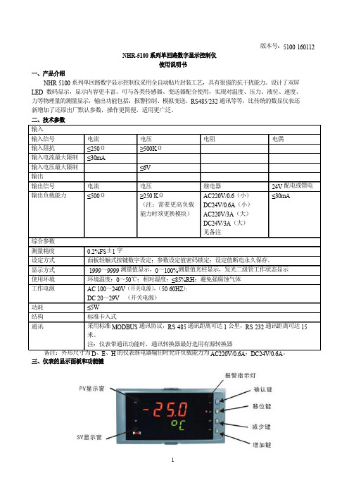
三、仪表的面板及显示功能
2)显示窗
PV显示窗:显示测量;在参数设定状态下, 显示参数符号
SV显示窗:显示输入分度号、报警值等,可根据要求自行选择显示;在参数设定状态下,显示设定参数值
3)面板指示灯4) 操作按键
从上至下依次为:从上至下依次:
AL1:第一报警指示灯确认键:数字和参数修改后的确认.
AL2:第二报警指示灯翻页键:参数设置下翻键
AL3:第三报警指示灯位移键:按一次数据向左移动一位
AL4:第四报警指示灯返回键:长按2秒可返回上一级参数
减少键:用于减少数值
增加键:用于增加数值
5)标准配线
仪表在现场布线注意事项:
PV 输入(过程输入)
1. 减小电气干扰,低压直流信号和传感器输入的连线应远离强电走线。
如果做不到应采用屏蔽导线,并在
一点接地。
2. 在传感器与端子之间接入的任何装置,都有可能由于电阻或漏流而影响测量精度。
热偶或高温计输入
应采用与热偶对应的补偿导线作为延长线,最好有屏蔽
RTD(铂电阻)输入
三根导线的电阻必须相同,导线电阻不能超过15Ω
四、仪表型谱及接线图
1、 仪表型谱
NHR-5100
—
)— )
(1) (2) (3)(4) (5)(6) (7) (8) (9)
2、 仪表接线图
注: 外形代码为F的电压、电流输入必须通过短路环切换外形代码为F的主板示意图如下:
J1、J2为第一路输入信号切换位置
J3、J4为第二路输入信号切换位置
五、通电设置
仪表接通电源后,即进入自检状态,自检完毕后,仪表自动转入工作状态,在工作状态下,按压键显示LOC,
LOC参数设置有如下:
1、1)Loc等于任意参数可进入一级菜单(LOC=00;132时无禁锁);
2) Loc=132,可进入二级菜单;
3) Loc=130,可进入时间设置菜单;对于带打印功能的表。
4) Loc等于其他值,按键4秒退出到测量画面。
2、如果Loc=577,在Loc菜单下,同时按住键和增加键达4秒,可以将仪表的所有参数恢复到出厂默
认设置。
注意:一旦操作成功,参数不可再恢复回刚才数值。
3
键4秒可退出到测量画面。
4、采用热电偶信号输入时,通道小数点dP=0时,温度显示分辨率为1℃;dP=1时,温度显示分辨率为
0.1℃,(1000℃以上自动转为1℃分辨率)。
★返回工作状态
1.
4秒后,仪表即自动回到实时测量状态。
2.自动返回:在仪表参数设定模式下,不按任何按键,30秒后,仪表将自动回到实时测量状态。
六、参数设置
6.1 一级参数设置
PV显示LOC,SV显示参数数值:按压增加、减少键来进行设置,Loc等
于任意参数可进入一级参数。
一级参数如下:
6.2二级参数设置
在工作状态下,PV 显示LOC ,SV 显示参数数值:按压增加、减少键来进行设置,当Loc=132
4秒,可进入二级参数。
二级参数如下:
表1
表2
七、 仪表参数说明
1.报警输出(AL1、AL2、AH1、AH2) ★关于回差:
本仪表采用报警输出带回差,以防止输出继电器在或报警输出临界点上下波动时频繁动作。
具体输出状态如下:
★测量值由低上升时: ★测量值由高下降时 :
★位式上限报警输出: ★位式下限报警输出:
2.滤波系数—采样的次数,用于防止测量显示值跳动
采样周期—模拟量输入时,仪表每次数据采集的时间为0.5秒 仪表PV 显示值与滤波系数及采样周期的关系如下 例:模拟量输入时,设定滤波系数为6(次),则仪表自动将(6×0.5)3秒内的采样值进行平均,
递推法更新PV 显示。
(即每次显示均这前3秒的采样平均值) 3.显示输入的迁移与放大:
定期校对时,可调整Pb 及Pk 改变测量值显示误差。
Pb 及Pk 的计算公式:Pk = 设定显示量程 ÷ 实际显示量程 ×原Pk
Pb = 设定显示量程下限 – 实际显示量程下限×Pk +原Pb
例:一直流电流 4~20mA 输入仪表, 测量量程为 - 200 ~ 1000 KPa , 现作校对时发现输入4 mA
时显示 -202 ,输入 20 mA 时显示1008 。
(原Pb=0,原Pk=1.000) 根据公式: Pk=设定显示量程÷实际显示量程×原KK1 =[1000-(-200)]÷[(1008-(-202)]×1=1200÷1210×1≈0.992 Pb= 设定显示量程下限- 实际显示量程下限×Pk+原Pb1
= -200 - (-202×0.992 )+0 = 0.384
设定:Pb=0.384 ,Pk=0.992 4.变送输出迁移1Oub 、1OuK ,2Oub 、2OuK 仪表变送输出以0~20mA 或0~5V 校对,如欲更改输出量程或输出偏差调整,可以利用以下公式实现。
满量程预定输出下限
当前输出下限当前新--
=Oub Oub
满量程
预定输出上限
当前输出上限当前新--
=K K Ou Ou
公式中,当输出为电流信号,满量程=20mA ,当输出为电压信号,满量程=5V 。
例1:变送电流0~20mA 输出,现欲改为4~20mA 输出。
测量时,输出零点值输出为0mA ,输入满量程时输出为20mA ,当前Oub =0,当前OuK =1。
2.020
4
00=--
=Oub 新
120
20
201K =--
=Ou 新 所以,将Oub 设置为0.2,OuK 不变,就实现了从0~20mA 输出改为4~20mA 输出了。
例2:变送电流4~20mA 输出,测量时,输出零点值输出为4.2mA ,输入满量程时输出为20.5mA ,当前Oub =0.2,当前OuK =1。
19.0204
2.42.0=--
=Oub 新 975.02020
5.201K =--=Ou 新
5.光柱显示方式:
光柱显示:如测量量程为0~100,当前测量值为50,则光柱 显示从0~50全亮。
光柱显示量程:光柱显示量程为ZL 、ZH 设定量程的百分比。
如: 1).设定量程为0~100,当前测量值为50,则光柱显示为50% 。
2).设定量程为0~1000,当前测量值为500,则光柱显示为50% 。
3).设定量程为0~2000,当前测量值为1000,则光柱显示为50% 。
八、打印功能
1、手动打印
在仪表测量值显示状态下,按压
键,即打印出当前的实时测量值。
2、定时打印
当时间测定等于间隔时间时,仪表将控制打印机进行定时打印,定时打印时将打印当前实时测量值。
打印格式为:
------------------------- ALM PRINT
2009-05-15 ----------------------日期 11:06:03 ----------------------时间 PV= -250℃ -----------------------测量值 ALM :
-----------------------报警状态
----------------- 3、接线方式
九、通讯设置
本仪表具有与上位机通讯功能,上位机可完成对下位机的自动调校、参数设定、数据采集、监视控制等功能。
配合工控软件,在中文WINDOWS 下,可完成动态画面显示、仪表数据设定、图表生成、存盘记录、报表打印等功能。
技术指标 通讯方式 串行通讯RS-485,RS-232等波特率300 ~ 9600 bps
单回路数字显示控制仪
数据格式一位起始位,八位数据位,一位停止位
★具体参数请参见《仪表通讯手册》
本仪表可与各种带串行输入输出的设备直接进行联机控制。
- 11 -。