灯串使用说明书
深圳市天成照明有限公司 TX1812HC 智能外控 LED 光源规格书说明书
◆Description(描述)TX1812HC是一个集控制电路与发光电路于一体的智能外控LED光源。
其外型与一个3838LED灯珠相同,每个元件即为一个像素点。
像素点内部包含了智能数字接口数据锁存信号整形放大驱动电路,电源稳压电路,内置恒流电路,高精度RC振荡器,输出驱动采用专利PWM技术,有效保证了像素点内光的颜色高一致性。
数据协议采用单极性归零码的通讯方式,像素点在上电复位以后,DIN端接受从控制器传输过来的数据,首先送过来的24bit数据被第一个像素点提取后,送到像素点内部的数据锁存器,剩余的数据经过内部整形处理电路整形放大后通过DO端口开始转发输出给下一个级联的像素点,每经过一个像素点的传输,信号减少24bit。
像素点采用自动整形转发技术,使得该像素点的级联个数不受信号传送的限制,仅仅受限信号传输速度要求。
LED具有低电压驱动,环保节能,亮度高,散射角度大,一致性好,超低功率,超长寿命等优点。
将控制电路集成于LED上面,电路变得更加简单,体积小,安装更加简便。
◆Applications(领域)LED全彩发光字灯串,LED全彩模组,LED幻彩软硬灯条,LED护栏管,LED外观/情景照明。
LED点光源,LED像素屏,LED异形屏,各种电子产品,电器设备跑马灯。
◆Features(特征)LED内部集成高质量外控单线串行级联恒流IC。
控制电路与芯片集成在SMD3838元器件中,构成一个完整的外控像素点,色温效果均匀且一致性高。
内置数据整形电路,任何一个像素点收到信号后经过波形整形再输出,保证线路波形畸变不会累加。
内置上电复位和掉电复位电路,上电不亮灯。
灰度调节电路(256级灰度可调)。
默认输出恒流值12mA,便于降低灯珠功耗。
默认上电不亮灯。
数据传输频率可达800Kbps,当刷新速率30帧/秒时,级联数不小于1024点。
◆Package Dimensions(封装尺寸)注;1.所有标注尺寸的单位均为毫米2.除了特别注明,所有标注尺寸的公差均为±0.2mm3.封装尺寸:3.5x3.5x1.3mm◆Product naming principle(产品命名原则)◆Pin figure(引脚图)◆Pin function(引脚图)序号符号管脚名功能描述1GND地信号接地和电源接地2NC空脚PCB上做悬空处理3DIN数据输入控制数据信号输入4VDD电源供电管脚,PCB上两供电管脚可做连通处理5VDD电源供电管脚,PCB上两供电管脚可做连通处理6DO数据输出控制数据信号输出Electro-optical characteristics at Ta=25℃(电光特性)◆Absolute maximum ratings at Ta=25℃(绝对最大额定值)参数符号范围单位逻辑电源电压VDD 3.0~+7.5V R/G/B输出端口电压Lol15mA 工作温度Topt-40-85℃℃储存温度Tstg-40-120℃℃◆Electric Spec(电气参数)参数符号最小典型最大单位测试条件芯片输入电压VDD-- 5.07.5V--OUT输出电流Iout--12--mA--高电平输入电压Vin0.7V DD----V VDD=5.0V 低电平输入电压Vil----0.3V DD V VDD=5.0V PWM频率FPWM--4--KHZ--静态功耗IDD--0.3--mA--◆dynamic parameter (动态参数)参数符号最小典型最大单位测试条件数据速率F DIN --8001100KHZ --传输延迟时间Tpzl--500--nsDIN-DO◆The data transmissiontime (数据传输时间)◆Temporal waveform figure (时序波形图)输入码型:连接方式:码码码◆mode of data transmission(数据传输方式)◆mode of data transmission(数据传输方式)G7G6G5G4G3G2G1G0R7R6R5R4R3R2R1R0B7B6B5B4B3B2B1B0注:高位先发,按照GRB的顺序发送数据(G7→G6 0◆Typical application circuit(典型应用电路)◆Typical optical characteristics curves (典型光学特性曲线)1.21.00.80.60.40.20.0400 450 500 550 600 650 700Wavelength[nm]Spectral DistributionRelative Intensity vs.Wavelength(Ta=25。
LED双色矩阵灯说明书
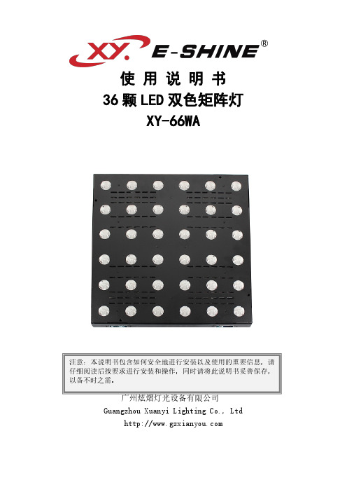
使用说明书36颗LED 双色矩阵灯XY-66WA广州炫熠灯光设备有限公司Guangzhou Xuanyi Lighting Co.,Ltd注意:本说明书包含如何安全地进行安装以及使用的重要信息,请仔细阅读后按要求进行安装和操作,同时请将此说明书妥善保存,以备不时之需。
1.数码管显示部分:A.功能键B.加键C.减键D.确认键A B C D2.LED显示窗功能对照表(所有的功能按选定后再按D键确认即可)序号显示功能说明1d001~d512DMX512通道地址码,(001—512)B、C键加减地址码数值272ch/06ch通道选择(72通道/06通道)B、C键加减3run1~run2自走模式(内置图形自走,内置效果自走)B、C键切换模式4bE-1~bE-9声控跑动变化,(01—09)B、C键修改声控灵敏度5y000~y255LED测试模式,(000—255)B、C键修改亮度值3.DMX5126通道说明序号功能说明第1通道白色总调光线性调光,由暗到亮第2通道琥珀色总调光线性调光,由暗到亮第3通道频闪同步频闪,由慢到快第4通道内置图形0--4:全亮;5--9:图形1;10--14:图形2;。
250--254:图形50;255:图形51;(备注:图形可以调光,频闪,优先级低于第4通道)第5通道内置效果0--7:无;8-15:效果1;249-255:效果31;(备注:效果模式可以调光,不能频闪,优先级高于第3通道)第6通道内置跑动速度功能速度,由慢到快(备注:0-127由快到慢,128-255效果倒过来跑由慢到快)4.DMX51272通道说明序号功能说明第1通道W1调光W1线性调光,由暗到亮第2通道W2调光W2线性调光,由暗到亮第....通道......调光......线性调光,由暗到亮第36通道W36调光W3线性调光,由暗到亮第37通道Y1调光Y线性调光,由暗到亮第38通道Y2调光Y线性调光,由暗到亮第....通道......调光......线性调光,由暗到亮第72通道Y36调光Y3线性调光,由暗到亮5.功能特点:操作非常简单,人性化设计,调光无闪烁、抖动现象等。
18颗小帕灯使用说明书

18颗小帕灯使用说明书1.按键操作
MENU UP DOWN ENTER
基本用法
MENU 主菜单切换/退出子菜
单UP参数调节
DOWN参数调节
ENTER确定/保存/进入子菜单
2.数码管LED显示功能对应表
序号显示功能说明
1 D001-D51
2 八通道地址码
2 CC00-CC99 七色跳变---速度不同
3 CP00-CP99 七色渐变,脉变变---速度不同
4 DE00-DE99 七色组合变化---速度不同
5 BEBE 七彩色声控变化
6 R000-R255 红色选色
7 G000-R255 绿色选色
8 B000-R255 蓝色选色
9 W000-R255 白色选色---此功能是预留(18颗没有)
序号功能说明
第1通道总调光R,G,B,W总调光,线性调光,由暗到亮第2通道总频闪R,G,B,W频闪,有慢到快
第3通道功能选择0-50为DMX八通道控制,50-100为跳变,101-150为渐变151-200为脉变,201-255为声控
第4通道功能速度功能速度---有慢到
第5通道R调光R调光--线性调光,由暗到亮第6通道G调光G调光--线性调光,由暗到亮第7通道B调光B调光--线性调光,由暗到亮。
西锐LED照明灯具使用手册说明书

PLEASE READTHIS USER GUIDE BEFORE INSTALLING, OPERATING OR PERFORMING MAINTENANCE ON THE ILLUMINATOR UNIT PRODUCT USER GUIDESirius Illuminator RangeE357731Rev: C3Thank you for purchasing this UFO illuminator/luminaire.To ensure that the illuminator is set up optimally and gives a long service life, please read this user guide before installing, operating or performing any maintenance on the unit.Please keep this User Guide for future reference. This User Guide is laid out in three sectionsInstallation -details on how to connect your luminaireOperation - details how to programme and set up your luminaireMaintenance - maintenance log, troubleshooting guide, technical specificationMODELS COVERED BY THIS USER GUIDEUFOSIRCW UFOSIRCW-C UFOCIRCW-T UFOSIRCW-Cs UFOSIRCW-TsUFOSIRSW UFOSIRSW-C UFOSIRSW-T UFOSIRSW-Cs UFOSIRSW-TsUFOSIRNW UFOSIRNW-C UFOSIRNW-T UFOSIRNW-Cs UFOSIRNW-TsUFOSIRWW UFOSIRWW-C UFOSIRWW-T UFOSIRWW-Cs UFOSIRWW-TsUFOSIRGW UFOSIRGW-C UFOSIRGW-T UFOSIRGW-Cs UFOSIRGW-TsUFOSIRGW27UFOSIRGW27-C UFOSIRGW27-T UFOSIRGW27-Cs UFOSIRGW27-Ts IMPORTANTThis product must be installed in accordance with the applicable installation code, by a person familiar with the construction and operation of the product, and the hazards involved.These illuminators are not mains dimmable.The LED array and heatsink in this illuminator can be replaced when it reaches end of life. Contact UFO for details.Type Y Attachment: If the external flexible cable or cord of this luminaire or associatedPSU/driver is damaged, it shall be exclusively replaced by the manufacturer or his service agent or a similar qualified person to avoid a hazard.Location: Do not locate this illuminator closer than 200mm from any flammable surface.Clearance / Ventilation: It is imperative that a gap of 200mm is left around the unit. This is to allow air to circulate and prevent overheating. The location must have free ventilation and must not have an ambient temperature higher than that specified for the luminaire.Mounting: This luminaire comes with an integral mounting plate for securing the unit to a vertical or horizontal surface. Refer to the instruction sheet supplied with the plate. Warning: Never look directly at the luminaire through the fiber port of the illuminator. Warning: The luminaire should be positioned so that prolonged staring into theluminaire at a distance closer than 2.7 metres is not expected.23UFO LIGHTING1. Manual dimming - local and remote2. No sensor, manual decorative wheel control (wheel speeds 0.5rpm, 1.2rpm, 2.4rpm, 4rpm, 7.5rpm and stop), stop on random color3. Sensor, manual decorative wheel control (wheel speeds 1.6rpm, 2.6rpm, 3.75rpm, 5.5rpm and stop), stop on 1 color4. DMX dimming5. No sensor - DMX decorative wheel control, adjustable speed from stop up to 7.5rpm + LED and fan on/off6. Sensor - DMX decorative wheel control, snap colors andadjustable speed from stop up to 7.5rpm + LED and fan on/off 7. No sensor - 0-10v decorative wheel control, adjustable speed from stop up to 7.5rpm - channel 1 (receiving)8. Sensor - 0-10v decorative wheel control, snap colors andadjustable speed from stop up to 7.5rpm - channel 1 (receiving)9. 0-10V dimming – channel 2 (receiving) - two versions, standard and emergency lightThe Sirius is a 90W white light LED illuminator with optional decorative wheel capability. The Sirius LED illuminator driver PCB has all the control functionality fitted as standard. The following control functionality and configurations are available.MODEL TYPESThe Sirius LED illuminator incorporates a range of LED arrays focussed through a series of static lenses to provide optimum display and illumination within the following optical range.MODEL TYPES [CONT ]SIRIUS RANGE USER GUIDE4CONNECTIONS AND CONTROLS OVERVIEW0-10VDIMMING DMX 24V DC INPUT MANUAL DIMMINGMANUALDMX ADDRESS AND CONTROLMOUNTING FEETThe illuminator is supplied with non-slip rubber feet pre-fitted the base of the unit. Alsoin the box there are 2 x user fixable mounting brackets which allow for the illuminator tobe securely mounted to a wall or other surface if necessary.To fit these feet, remove the 4 rubber feet from the base of the unit and retain the screws.The wall mounting brackets are supplied as a pair - one left and one right hand. Positionthe brackets over the holes that have been left empty by the rubber feet and fix in placewith the removed screws.The illuminator can now be fixed to the mounting surface.5SIRIUS RANGE USER GUIDE6CONNECTION - FOR LOCAL MANUAL OPERATIONThere are 2 connections required – the fiber port and the mains supply cable. The fiber port should be connected first. Connect and secure the fiber optic connector into the collar and secure using the M5 locking screw.Connect the PSU to the DC input jack socket on the illuminator, and connect the IEC plug to the PSU. Plug the mains plug into the electrical supply socket. Switch on power. The LED Indicator on the PSU will illuminate and the illuminator is ready for use. If no light is produced consult the TROUBLESHOOTING section of this user guide.CONNECTION - FOR LOCAL MANUAL OPERATION There are 3 connections required – the fiber port, the remote dimmer cable and the mains supply cable. The fiber port should beconnected first. Connect and secure the fiber optic connector into the collar and secure using the M5 locking screw. Connect the RJ45 connector on the end of the remote dimmer cable as detailed below into the right hand RJ45 socket (0-10V dimming) on the side of the illuminator.Connect the PSU to the DC input jack socket on the illuminator, and connect the IEC plug to the PSU. Plug the mains plug into the electrical supply socket. Switch on power. The LEDIndicator on the PSU will illuminate and the illu-minator is ready for use. If no light isproduced consult the TROUBLESHOOTINGsection of this user guide.7There are 3 connections required – the fiber port, the mains supply cable and the DMX cables. The fiber port should be connected first. Connect and secure the fiber optic connector into the aluminium collar and secure using the M5 locking screw.Connect the PSU to the DC input jack socket on the illuminator, and connect the IEC plug to the PSU. Plug the mains plug into the electrical supply socket. Switch on power. The LED Indicator on the PSU will illuminate and the illuminator is ready for use. If no light is produced consult the TROUBLESHOOTING section of this user guide.Connect to the 3 pin XLR sockets on the side panel as detailed below using an approved DMX cable.Only approved DMX cables should be used.Always “daisy chain” a DMX universe. Never use a T joint in a DMX universe unless using an approved interface.It is always recommended that the last illuminator output in the DMX universe or cable run be terminated with a 120 ohm resistor across DMX+ and DMX-.SIRIUS RANGE USER GUIDE8There are 3 connections required – the fiber port, the mains supply cable and the 0-10V cable. The fiber port should be connected first. Connect and secure the fiber optic connector into the aluminium collar and secure using the M5 locking screw.Connect the PSU to the DC input jack socket on the illuminator, and connect the IEC plug to the PSU. Plug the mains plug into the electrical supply socket. Switch on power. The LED Indicator on the PSU will illuminate and the illuminator is ready for use. If no light is produced consult the TROUBLESHOOTING section of this user guide.Connect the 0-10V RJ45 as detailed below using CAT5 cable.Note : for emergency light functionality, the mains supply for the illuminator must bemaintained so that failure of the mains supply to the 0-10V controller will result in the illumina-0-10V RJ45 Connections:-VE RJ45 Brown/White (Pin 7) +VE RJ45 Blue/White (Pin 5)POWER SUPPLY REQUIREMENTSThe LED illuminator is powered from a 24V DC PSU/Constant Voltage SELV LED driver.The driver caters for UK/European/other mains supplies using the relevant power cord supplied.9UFO LIGHTINGLOCAL WHITE LIGHT DIMMINGAll Sirius models in the range can be manually controlled as detailed in the following sections.Note: For all manual operation modes, dip switch 10 must be set to on.During normal manual white light operation, the illuminator can be dimmed from 0 to 100% using the manual dimming control on the side panel.EMERGENCY WHITE LIGHT DIMMINGDuring normal manual white light operation the emergency light configured illuminator can be dimmed from maximum light at 0%, to no light at 10% then again up to maximum light at 100% using the manual dimming control on the side panel.DECORATIVE COLOR OR TWINKLE WHEEL CONTROL - WITHOUT SENSORDuring normal manual decorative operation the illuminator can be dimmed from 0 to 100% using the manual dimming control and the motor can be controlled from stop to 5 speeds (see table below) using the push button manual motor control on the side panel.Note: When manually selecting stop (switch position 6) the decorative wheel will stop instantly on a random color (color wheel) or a random section of the twinkle wheelREMOTE WHITE LIGHT DIMMINGDuring remote manual white light operation, the illuminator can be dimmed from 0 to 100% using the remote dimming control.Note : For remote manual dimming operation, dip switch 10 on the illuminator must be set to on and the local manual dimming control on the side of the illuminator must be turned to mini-mum (fully counter clockwise)SIRIUS RANGE USER GUIDE10DECORATIVE TWINKLE WHEEL CONTROL - WITH SENSORDuring normal manual decorative operation the illuminator can be dimmed from 0 to 100% using the manual dimming control and the motor can be controlled with stop + 4 speeds ranging from very slow to fast using the push button manual motor control on the side panel.Note: For this configuration the twinkle wheel is supplied with a cut out segment. The wheel in motion will give an uninterrupted twinkle by rotating backwards and forwards either side of the segment. When stop is selected the wheel will come to rest at the segment giving unobstructed white light output.DECORATIVE COLOR WHEEL CONTROL - WITH SENSORDuring normal manual decorative operation the illuminator can be dimmed from 0 to 100% using the manual dimming control and the motor can be controlled from stop to 4 speeds (see table below) using the push button manual motor control on the side panel.Note: When manually selecting stop (switch position 5) the decorative wheel will automatically return to color 1 (normally white)DMX OPERATIONEach Sirius occupies 3 DMX channels• Channel 1 dimming• Channel 2 decorative wheel control • Channel 3 LED and fan ON/OFF controlDecorative wheel DMX functions are different depending on decorative model. More details on individual DMX channels and values are provided in the following DMX tablesNote : For ALL DMX operations, DIP switch 10 on the illuminator must be set to off, the correct DMX address must be set (switches 1-9) and the XLR plug(s) must be plugged into the XLR sockets on the side panel.11LIGHTINGSETTING THE DMX ADDRESSBecause the Sirius occupies 3 DMX channels, when setting addresses on multiple illuminators the addresses must be selected to give 3 channel separation. For example, if the first address is 009, the next address must be at least 012, the next address must be at least 015 and so on. Any illuminators with the same address will operate identically under DMX control.The DMX address is set manually using the DIP switch on the side panel of the Sirius. Each DIP switch number (1 to 9) represents a binary number which when added together make up the DMX address as shown in the table below.WHITE LIGHT DIMMINGThe illuminator can be dimmed on DMX channel 1 and controlled on DMX channel 3 as detailed in Table A. DMX Channel 2 is redundant.Alternatively use the online calculator from link below: /calc.aspSIRIUS RANGE USER GUIDE12The Illuminator can be controlled as detailed in Table ASIRIUS DMX CHANNELS - TABLE AEach Sirius occupies 3 DMX channels as detailed below.DECORATIVE COLOR OR TWINKLE WHEEL CONTROL - WITH SENSORFor this configuration of a decorative wheel with sensor:• The Twinkle wheel has a cut-out segment. The wheel in motion will give an uninterrupted twinkle by rotating backwards and forwards either side of the cut-out segment. When stopped the wheel will return to the cut-out segment and display unobstructed white light • The color wheel when stopped will return to color wheel segment 1 (normally white) The Illuminator can be controlled as detailed in Table B for Color Wheel with sensor and Table C for Twinkle Wheel with sensorDECORATIVE COLOR OR TWINKLE WHEEL CONTROL - NO SENSORFor this configuration of a decorative wheel without sensor:• The Twinkle wheel is solid with no cut out segment. The wheel in motion will give a continu-ous twinkle effect. When stopped the wheel will remain in front of the LED array giving an ob-structed white light output• The color wheel when stopped will display the color where it stoppedThe illuminator decorative wheel can be controlled on DMX channel 2 as shown in table A.SIRIUS DMX CHANNELS - TABLE BEach Sirius occupies 3 DMX channels as detailed below.13 LIGHTINGSIRIUS DMX CHANNELS - TABLE CEach Sirius occupies 3 DMX channels as detailed below:14SIRIUS RANGE USER GUIDE15UFO LIGHTINGSTANDARD WHITE LIGHT DIMMINGOnce the Sirius illuminator has been set up and connected as detailed above the illuminator can be dimmed from 0 (0 Volts DC) to 100% (10V DC) with a receiving 0-10V signal.EMERGENCY WHITE LIGHT DIMMINGOnce the Sirius illuminator has been set up and connected as detailed above the illuminator can be dimmed with a receiving 0-10V signal as detailed in the table below:Note: In this configuration when the mains supply to the 0-10V controller fails, the illuminator will illuminate fully as an emergency light.For ALL 0-10V operation control DIP switch 10 on the Sirius illuminator side panel must be set to ON and in addition:• For 0-10V dimming the Manual Dimming Control on the Sirius illuminator side panel must be set to minimum (fully counter clockwise) and the RJ45 plug must be plugged into the right hand (0-10V dimming) RJ45 socket on the side panel.• For 0-10V decorative wheel control the Manual Motor Control on the Sirius illuminator side panel must be set to STOP and the RJ45 plug must be plugged into the left hand (0-10V motor.SIRIUS RANGE USER GUIDE16DECORATIVE COLOR OR TWINKLE WHEEL CONTROL - WITH SENSOROnce the Sirius illuminator has been set up and connected as detailed above the illuminator decorative wheel can be controlled with a receiving 0-10V signal as detailed in the following table:DECORATIVE COLOR OR TWINKLE WHEEL CONTROL - NO SENSOROnce the Sirius illuminator has been set up and connected as detailed above the illuminator decorative wheel can be controlled with a receiving 0-10V signal from stop at 0V to 7.5rpm at 10VNote: For this configuration the twinkle wheel is solid without a cut out segment.DECORATIVE TWINKLE WHEEL CONTROL - WITH SENSOROnce the Sirius illuminator has been set up and connected as detailed above the illuminator decorative wheel can be controlled with a receiving 0-10V signal to give stop (0V DC) to varying speeds (0.5 to 10V DC) ranging from very slow to fast.Note: For this configuration of a twinkle wheel with sensor, the wheel is supplied with a cut out segment. The wheel in motion will give an uninterrupted twinkle by rotating backwards and for-wards either side of the segment. When 0V is selected the wheel will come to rest at the segment giving unobstructed white light output.MAINTENANCELOGMAINTENANCE17 LIGHTINGTROUBLESHOOTINGSIRIUS RANGE USER GUIDE18[1] - white light manual dimming version / [2] - decorative manual motor version / [3] - DMX only [4] - decorative or dimming 0-10V control / [5] - dimming 0-10V control / [6] - 0-10V controlTECHNICAL SPECIFICATION19UFO LIGHTINGDESIGNSPECIFYBUILDINSTALLUnited Kingdom •United States • Germany •Europe • UAEUFO Licht GmbH\ Gutenbergstraße 185737 Munchen \ Deutschland+49 (0)9491 955880 www.ufo-licht.deUniversal Fiber Optics USA LLC\\Universal Fiber Optics Ltd \\。
灯光组合开关使用手册.doc
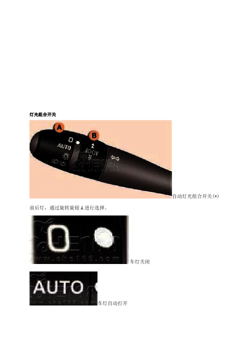
灯光组合开关自动灯光组合开关(*) 前后灯,通过旋转旋钮A进行选择。
车灯关闭车灯自动打开位置灯近光灯/远光灯手动灯光组合开关(*) 前后灯,通过旋转旋钮A进行选择。
车灯关闭位置灯近光灯/远光灯远光/近光转换,将组合开关朝您的方向拉动。
忘记关闭车灯点火开关关闭后,车灯自动照明功能被关闭,在驾驶员打开车门时会有蜂鸣信号响起,提醒驾驶员还未关闭车灯。
前/后雾灯,向前旋转旋钮B打开雾灯向后转动则关闭。
其状态通过仪表盘上指示灯显示。
前雾灯(旋钮向前转动一次)旋钮A在位置灯或近光灯位置时雾灯才能打开。
前雾灯和后雾灯(旋钮向前转动二次)。
注意:将旋钮向后转动二次,关闭后雾灯和前雾灯。
无论在晴天还是雨天、白天还是夜晚,雾灯开启都非常耀眼,切记在不需要时将其关闭。
转向指示灯(闪烁灯)左:向下,右:向上自动延时照明(伴我回家) (*)点火开关断开后,当您在车灯自动照明激活状态下离开您的汽车时,位置灯和近光灯会在设定的时间内保持亮起状态。
可以通过多功能显示屏上的“车辆参数”菜单关闭或激活该功能。
延时照明时间可以通过多功能显示屏菜单设定(15,30、60秒)。
取消-闪动大灯一次,-下车并锁好车门。
手动延时照明(伴我回家) (*)车灯自动打开功能关闭时,位置灯和近光灯会和自动延时照明功能一样,在设定的时间内保持亮起。
对于未装备自动大灯的汽车,当离开您的汽车时,位置灯和近光灯会保持亮起30秒。
启动-关闭发动机,-将灯光组合开关向驾驶员方向拉动一次,-下车并锁好车门。
关闭-再次将灯光组合开关向驾驶员方向拉动一次,-下车并锁好车门。
车灯自动打开(*)前位置灯和近光灯在光线弱和雨刮器处于连续工作状态时会自动亮起,并在光线足够亮时或雨刮器停止工作时自动熄灭。
注意:雾天或雪天,亮度传感器可能探测到足够的亮度,因此,大灯并不自动打开。
激活-将旋钮A转到“AUTO”位置上。
该功能被激活时,激活信息会显示在多功能显示屏上。
关闭-将旋钮A转到非“AUTO”位置。
灯串使用说明书

灯串使用说明书一、产品概述灯串是一种用于室内和室外装饰的照明产品,由一系列小灯泡串联而成。
它具有丰富多样的颜色和灯效,可以用于节日庆祝、室内装饰和户外景观等场合。
本使用说明书将详细介绍灯串的使用方法和注意事项,以确保您的安全和便利。
二、产品特点1. 灯效丰富:灯串可提供多种灯效,如常亮、闪烁、渐变等,能够满足不同场合的需求。
2. 节能环保:灯串采用LED灯泡,具有低能耗、长寿命和环保的特点。
3. 防水设计:灯串的线缆和插头经过防水处理,可以安全使用于室内和室外环境。
4. 易于安装:灯串采用插拔式设计,方便用户进行安装和拆卸。
三、使用方法1. 检查灯串是否完好:在使用之前,请检查灯串的电线、插头和灯泡是否完好,如有损坏或松动情况,请勿使用。
2. 安装灯串:根据需要,选择合适的安装位置,将灯串固定或悬挂在相应的支架或物体上。
3. 连接电源:将灯串的插头插入电源插座,确保插头与插座连接稳固,避免电源短路或漏电。
4. 开关操作:部分灯串配备开关,按下开关即可控制灯串的开关和灯效,如无开关,请直接插上电源即可点亮灯串。
5. 调整灯效:根据个人需求,调整灯串的灯效,如常亮、闪烁或渐变等。
部分灯串可以通过遥控器或调节器进行调整,具体操作请参考产品说明书。
6. 关闭灯串:使用完毕后,务必将灯串的开关关闭,并拔掉电源插头,以确保安全和节能。
四、注意事项1. 使用场所:请根据产品说明书的要求,选择适合的使用环境。
室外使用时,请确保灯串具备防水功能,避免暴露在雨水中。
2. 电源安全:使用时请注意电源的稳定和安全,避免电源过载或短路引起火灾或其他意外情况。
3. 儿童禁用:请将灯串放置在儿童无法触及的地方,以免发生触电或误食等危险。
4. 注意防火:使用时请勿将灯串放置在易燃物品附近,避免发生火灾。
5. 不可拆卸:请勿擅自拆卸灯串或更换零部件,以免破坏产品功能或造成安全隐患。
6. 长时间使用:长时间使用灯串时,请确保通风良好,避免过热引起安全问题。
LED红外感应灯产品说明说明书
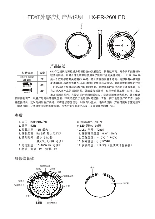
60m mmLED 红外感应灯产品说明 LX-PR-260LED产品描述LED作为近代光源已成为照明行业的发展趋势,具有效率高,寿命长和能耗相对较低的特点,如何合理及效率地使用成了照明行业的关键问题。
LX-PR-260LED是一个红外感应开关控制的LED灯,红外传感器内置于灯内,内部具有90颗高亮度LED颗粒,总功率为13瓦,其合理的布局使得热流均匀,达到最优化的照明效率。
灯亮起时光照度超过60W白炽灯的亮度,同时续航时间也远超普通卤素灯。
当有人进入本产品的探测范围,并触发传感器时,红外传感器工作,灯亮;当人离开探测范围内,在设定延时时间到后灯灭。
自动探测环境光照度,并可依据实际需要调节、设置灯起亮的环境照度值,环境照度低于设定值时灯起亮、工作,高于设定值灯不工作。
触发感应亮灯后,延时时间到后灯关闭,如有连续感应信号,时间自动叠加,灯持续点亮。
产品可使用于室内照明;楼道照明;公共建筑区域的节能照明。
作为节能光源该产品是一个非常理想的替代品。
1.电压:220-240V/AC2.频率:50Hz3.负载功率:13W 最大4.探测距离:5±2米 最大(24°C )5.延时时间:最小12±3秒最大5±1分钟(可调)6.光控照度:10-2000LUX(可调)7.材质:灯体:PC 灯罩:PC参数8.待机功耗:<0.7W 9.LED 颗粒:90颗10.LED 型号:T283511.探测移动速度:0.6~1.5m/s 12.工作温度: –10°C ~ +40°C 13.相对湿度:小于95%RH14.安装高度:1.5-3米(吸顶或墙壁安装)各部位名称红外感应器PC灯罩光控时间图.1探测角度130°探测区域:由上下、左右服务区构成的大范围探测区,探测范围用户可根据自己的需要选择,但探测区内人行走方向与灵敏度有很大的关系;自动识别白天、黑夜:产品工作时的环境照度用户可以自行调整,调整至太阳(最大)时它不分白天和黑夜都能工作,调至月亮(最小)时它只能工作在10LUX 以下的环境中。
全彩外露灯(穿孔灯)说明书V1
全彩外露灯(穿孔灯)安装说明书V1.0外露灯(LED灯串)产品介绍LED外露灯产品的概述LED外露灯产品,是采用先进的高亮LED半导体芯片作为发光组件,配以先进设计、特殊工艺生产而成。
我公司有全彩、七彩、单色(红、黄、蓝、绿、白等5种)3大系列。
通过科学防水处理、独特的生产工艺,使发光字容易安装、降低成本、提升品质、节能省电、高亮度、色彩夺目等优点。
LED灯座有独特的卡口设计,非常方便取、装,维护变得更加简单;由于灯点是半隐藏式,所以使字或标识变得更美观大方!因它的绝对性价比等诸多优势,所以成为传统霓虹灯的换代产品。
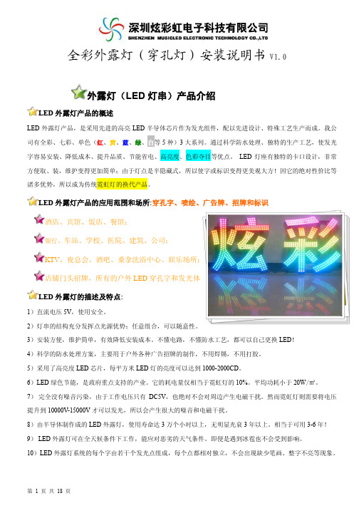
LED外露灯产品的应用范围和场所:穿孔字、喷绘、广告牌、招牌和标识酒店、宾馆、饭店、餐馆;银行、车站、学校、医院、建筑、公司;KTV,夜总会、酒吧、桑拿洗浴中心、娱乐场所;店铺门头招牌,所有的户外LED穿孔字和发光体。
LED外露灯的描述及特点:1)直流电压5V,使用安全。
2)灯串的结构充分发挥点光源优势:任意组合,可以随意性。
3)安装方便,维护简单,有效降低安装成本。
不懂电路,不懂防水工艺,都可以自己更换LED!4)科学的防水处理方案,主要用于户外各种广告招牌的制作,不用焊锡,不用打胶。
5)采用了高亮度LED芯片,每平方米LED灯的亮度可以达到1000-2000CD。
6)LED绿色节能,是政府重点支持的产业。
它的耗电量仅相当于霓虹灯的10%。
平均功耗小于20W/㎡。
7)完全没有噪音污染,由于工作电压只有DC5V,也绝对不会对周边产生电磁干扰。
然而霓虹灯则需要将电压提升到10000V-15000V才可以发光,所以会产生很大的噪音和电磁干扰。
8)由半导体制作成的LED外露灯,使用寿命达3万个小时以上,无明显光衰3年以上。
相当于可用3-6年!9) LED外露灯可在全天候条件下工作,能应对恶劣的天气条件。
即便是遇到冰雹也不会受到影响。
10)LED外露灯系统的每个字由若干个发光点组成,每个点都相对独立,不会出现缺少笔画、整字不亮等现象。
- 1、下载文档前请自行甄别文档内容的完整性,平台不提供额外的编辑、内容补充、找答案等附加服务。
- 2、"仅部分预览"的文档,不可在线预览部分如存在完整性等问题,可反馈申请退款(可完整预览的文档不适用该条件!)。
- 3、如文档侵犯您的权益,请联系客服反馈,我们会尽快为您处理(人工客服工作时间:9:00-18:30)。
灯串使用说明书
灯串使用说明书
1. 打开包装
- 将灯串小包装打开,并取出其中的灯串。
2. 灯串展开
- 将灯串展开,确保线条没有交叉,灯泡没有缠绕在一起。
3. 插电源
- 将灯串的插头插入电源插座。
确保插头与插座连接牢固。
4. 开关灯
- 寻找灯串上的开关按钮,打开开关按钮,灯串即可开始发光。
- 如果需要关闭灯串,再次按下开关按钮即可。
5. 悬挂灯串
- 根据需要,将灯串悬挂在所需位置。
可以使用钉子、钩子或其他固定装置固定灯串。
6. 调整灯串
- 可根据需要调整灯串的形状和布置。
可以拉直灯串或者使其呈现特定的形状。
7. 注意事项
- 使用灯串时,请确保插座和电源线没有暴露在水或者潮湿
的环境中,以免发生安全事故。
- 长时间使用灯串时,请定期检查灯串是否过热,避免潜在的火灾隐患。
- 在离开房间或者睡觉时,请关闭灯串,以节省能源和确保安全。
8. 清洁和维护
- 拔出电源插头之后,可以使用湿布轻轻擦拭灯串的表面,以保持其清洁。
- 避免使用化学清洁剂或者过于湿润的布料清洁灯串。
请仔细阅读以上使用说明,以确保正确安装和使用灯串,并避免潜在的安全问题。