
天行者2014 Skywalker 1900 安装说明书
Sky-Walker Pro Installation ManualThank you for purchasing the Sky-Walker Pro plane.The Sky-Walker Pro is designed for First-Person-Vision (FPV) application specifically.Due to the high wing and push prop design,the on-board camera could have a perfect view without being blocked.The large fuselage compartment design provides conveniency to contain almost any hobby FPV equipment.Other than that,the Sky-Walker Pro is also suitable for the beginners to leam flying as a high stable trainer plane.Before you start the installation,please read this manual carefully to have an overall idea of what to do.In the same time,please check all parts before you begin.If you find any missing or defective parts,please contact your local dealer.1,Required for Installation and Operation:1.1Required RC Equipments:The below listed RC gears are not included.They may need to be purchased separately.For details,please check with your local hobby stop.-Minimum 4-6 channel radio control system-Minimum 2 pieces of8- 9g micro servos or similar.4 servos are needed for full control of aileron,elevator and rudder- 2 pieces of 25~30cm servo extension cables for aileron servos-AXI 2820KV920-1100 out-runner brushless motor or equivalent-45-60A or above brushless ESC with 25~30cm length of the power input wire-APC9060E propeller or equivalent-5000mAh 4S lithium-polymer battery pack or similarYou may need the following for FPV application:-DC powered Camera-Pan/tilt camera mount with servos- 6 or more channel radio control system,instead of 3~4 channels for basic flying-Wireless transmitter and receiver for on-board video transmission-On-Screen-Display(OSD)system-1000mAh 3S lithium-polymer battery pack or similar for the camera(refer to the manual of the camera system)3- A 490-1hgfrewq1.2Required Tools and Material for Installation:-Phillips screwdriver&allen key-Sharp hobby knife-Hobby scissors-Needle nose pliers-Wire cutters-Awl-Marjer pen-Foam double-sided tape -Fibre tape-Paper tape-Cable tight-Male&female Velcro tape -Hot glue and hot glue gunParts listing :Step1:Free the aileron surfaces from the wing pieces with sharp hobby knife if the aileron control is needed.Trim off the un-necessary EPO material.Step2:Apply a thin layer of the EPO glue for the 2 EPO carbon tube slot covers .It is not recommended to apply glue on the contact surface between the EPO material and carbon tubes,unless you are planning to join the wing pieces permanently.Step3:Similarly,Apply a thin layer of the EPO glue on the wing pieces at the joint area of the 2 EPO carbon tube slot covers.Step4:Wait for about 1~2 minutes for the glue to solidified slightly before placing the 2 carbon tube covers.Step5:机翼加强碳片嵌入,在机翼碳片槽内均匀滴入胶水,再将碳片卡入槽内然后拉出,等待干燥2分钟再嵌入,即可固定。
Insert the carbon tube, supply the glue in the carbon tube slot and click the carbon tube into the slot and pull out, wait for 2 minutes and click into the slot once again for fixing.Step6:副翼舵机安装;将泡沫胶均匀涂抹在机翼的舵机槽和舵机上,等待5分钟然后将装好拉杆、测试好中立点的舵机压入槽内,这样舵机会跟舵机槽固定牢靠(请在之后的安装过程中按此方法使用胶水),然后用纤维胶带将舵机延长线封入线槽。
Aileron servor installation: supply the EPO glue slightly on the wings of servor slots and servors, wait for 5 minutes and insert the servor equiped with pull rods and neutral point tested into the slots. So this will make tight fixing between the servor and the slot (hereinafter the same), then seal the extension cord of the servor with fiber tape into the slot.Step7:拉杆与舵角连接:舵角用胶水均匀涂抹压入再拉出等待干燥再插入固定。
然后将调节器和拉杆连接(不需要将螺丝锁紧,待完成之后通电到中立点再锁紧),再用钳子将多余的拉杆适量剪除。
Junction of pull rod and rudder: slightly glue the rudder and click into, then pull out for drying and reinsert it for fixing. Connect the controller with the pull rod (screw it after finishing neutrol point tested). Cut out the needless pull rod properly.Step8:主机翼碳管对接:配件包内有2块翼型层板,这里不需要跟机翼粘黏,在您购买2014款skywalker 之后可以使用。
机翼的对接,可以用胶将碳管固定在任意一边机翼上,然后机翼对插连接(这样机翼跟机身会更加牢靠)。
Joint of the main wings: 2 pieces of wing layers included in the accessories bag, unnedessary to glue them on the wings. It is adaptable for 2014 Skywalker series.Joint of the wings, glue the carbon fiber on either side of the wing and plug it for tight connection.Step9:垂直尾翼和方向舵:用小刀将机身垂尾方向舵切开,再用胶水将调试好的舵机固定在舵机槽内。
Vertical tail and rudder: cut the vertical tail open with an knife, and glue the well-adjusted servor into the servor slots.Step10:机身碳管和延长线安装:将两根延长线塞入碳管内,然后用胶水将碳管固定在机身碳管槽内,(注意待胶水干透再粘合固定),将两根延长线与垂尾的两个舵机连接(用热缩管将接头套紧避免飞行震动松脱),然后将伸出的延长线用胶带临时固定,方便两片机身合拢。
MA1900机器人使用说明书-印刷版

请用 M16 的内六角螺栓 (推荐长度为 60mm)进行固定。六角螺栓和地角螺 栓要拧紧,确保设备在运行中不发生松动。
强制
• MOTOMAN-MA1900 机器人使用说明书是以机器人的机构内容为中心的 技术材料。为确保系统的正常应用和妥善保养及检修,其中包括安 全注意事项、使用注意事项、详细的规格说明、保养及检修的项目 等内容。请务必在认真阅读并充分理解和掌握的基础上使用。
• 另外,有关安全的详细内容记载在 《DX100 使用说明书》的 “第一 章 安全”中,阅读本使用说明书前,请务必熟读安全内容,以确保 正确使用。
HW0484970
注意
·起吊操作、天车或叉车的操作,请由有操作资格的人员进行。 否则可能发生人身伤害、设备损坏等事故。 ·搬运时,请避免过度振动或冲撞。 否则会影响精密设备的性能。
2.1.1 使用天车
2.1 搬运方法
机器人的开箱、移动和搬运,原则上要使用天车。 请利用附设的吊环及 2 根钢丝绳起吊机器人。 请务必用搬运夹具固定机器人后,按 「图 2-1 “搬运姿势”」所示姿势 (出厂姿态)起吊。
请确认机器人与 DX100 的订货号是否一致。订货号写在下图所示位置的标 签上。
图 1-1: 订货号标签位置
ᷛㅒᬒ
䇋ᇚϢϟ߫䅶䋻োⳌৠⱘ0RWRPDQᴎ఼ҎϢ ࠊᶰ䖯㸠䖲ᑊՓ⫼DŽ
14&'40Q
ᷛㅒϞݭ᳝䅶䋻োDŽ 䇋⹂䅸ᴎ఼Ҏⱘ䅶䋻োϢ'; ᷛㅒϞⱘ䅶䋻োᰃ৺ϔ㟈DŽ
Y
DX100
本书的表示 DX100 示教编程器 连接电缆
vi
HW0484970
MA1900
警告牌的说明
黑莎特尔空压模型AP1900安装、运行和维护指南说明书

TABLE OF CONTENTSInstallation and Setup (3)Maintenance (3)Disassembly (4)Troubleshooting Guide ...................................................................................................................... 4 & 5 Pneumatic Circuit .. (6)Part List (7)Parts Drawing (8)MACHINE GUARDINGMachine guarding is the responsibility of the user. Provisions must be made to protect the operator and other employees from injury as a result of contact with work in progress, moving parts, mechanical motions of the press, etc. Air-Hydraulics cannot provide “standard” guards for its products due to the variety of tooling used by its owners. However, Air-Hydraulics will be happy to install guards and similar safety devices for operator protection. These safety devices must be produced at the request of and with the design approval of the purchaser.WARRANTYWe warrant to the original user that all products of our manufacture will be free from defects in material and workmanship and will possess the characteristics represented in writing by us. Claim for breach of the above warranty must be made within a period of one (1) year from the date of delivery to the user. Upon satisfactory proof of claim, we will make any necessary repairs or corrections, or, at our option, replace defective parts at the factory, transportation charges prepaid. Charges for correcting defects will not be allowed, nor can we accept goods returned for credit unless we are notified in writing and the return or correction is authorized by us in writing. The FOREGOING IS IN LIEU OF ALL OTHER WARRANTIES, EXPRESSED OR IMPLIIED, INCLUDING ANY WARRANTIES THAT EXTEND BEYOND THE DESCRIPTION OF THE PRODUCT. This paragraph sets forth the extent of our liability for breach of any warranty in connection with the sale or use of our products. It is understood we will not be liable for consequential damage such as loss of profit, delays, or expense whether based on tort or contract.INSTALLTION1.Place press on rigid bench or table at a convenient height for operator. Bolt securely to thebench.2.Connect 100 P.S.I. filtered shop air supply (40 micron min) to 3/8 N.P.T. inlet port of pressureregulator.SET UP AND OPERATION1.Loosen locknut and adjust pressure regulator until pressure gauge reads desired pressure(100 P.S.I.). CAUTION: Do not operate at pressure greater than 125 P.S.I.2.Adjust speed control valve to slow position by turning valve stem clockwise (or in).3.Check to make sure safety sleeve assembly is in the correct position on the press beforeoperating4.Keeping hands clear of shaft, actuate press by depressing hand valve pedal (s).5.Release pedal (s). Shaft should return to fully retracted position.6.Remove safety sleeve from press.7.Loosen locking nut and adjust stop nut to obtain desired stroke. Distance between bottomof the stop nut and top surface of stop cap or frame is the stroke of the shaft. CAUTION: Donot back off locking nut beyond top of threaded shaft. Doing so may damage packings.8.Replace safety sleeve and re-actuate press.9.If necessary, re-adjust stop nut, speed control and pressure regulator to obtain desiredsetting. CAUTION: Never operate press unless safety sleeve is in place and hands are clearof shaft.10.Install tooling into hole provided in shaft, securing with set screw.11.Install dies, nests or anvils onto base using tapped holes provided.12.Make any final stroke, speed and pressure adjustments to obtain desired workpiececonfiguration with tooling in place.MAINTENANCELUBRICATIONAir presses are lubricated at the factory and should require no additional lubrication. However, if a press is disassembled for service or replacement of parts, all internal surfaces should be coated with a light bearing grease such as Lubriko M6 (Master Chemical Co.) or equivalent.CUSHION ADJUSTMENTModel AP 1900 employs an external cushion spring for the return stroke. The cushion is preset at the factory and should require no further attention. However, if the machine should begin to “hammer” during the return stroke, cushion adjustment may be necessary, as follows:1.Remove safety sleeve from press2.Loosen cushion adjustment locking nut.3.Rotate cushion adjustment locking nut upward to increase spring compression, slightly.4.Re-tighten locking nut.5.Replace safety sleeve.6.Adjust return speed control to maximum fast position.7.Actuate press & check for “hammering” during the return stroke8.If necessary, repeat cushion adjustment until ram returns gently to its rest position.9.Re-adjust return speed control to obtain desired return stroke speed.GIB ADJUSTMENTModel AP 1900 has a square shaft retained by two adjustable gibs. If any side play or rotation is noticed in the shaft of these models, a gib adjustment may be necessary. Adjustments as follows:1.Along the centerline of the shaft at the front and right side of the press, two (2) set screws willbe found for each of the two (2) gibs.2.Adjust set screws inward on one (1) gib at a time until all side play is removed from shaft. Donot overtighten gibs or press may jam or operate erratically. Gibs should be just tight enough to remove all side play and rotation from shaft.PRESS DISASSEMBLYShould press disassembly become necessary in order to service or replace parts, use extreme caution. These presses have a heavily compressed return spring under the flange nut.Remove air supply. Cylinder is now in retracted position. Slowly remove flange nut until spring compression is fully released. Failure to do so will result in flange nut and spring separating abruptly, possibly causing injury to personnel. Now remove any fastener you need to replace parts. Re-assembly should be approached with the same cautious manner. Torque cylinder mounting fasteners to 23 ft. lbs. each.Air-Hydraulics, Inc. maintains complete facilities at all times for the repair of air presses. If qualified maintenance personnel are not available at a customer’s plant, the press may be returned to the Air-Hydraulics, Inc. for service.TROUBLESHOOTING GUIDEPNEUMATIC DIAGRAMSINGLE ACTING CYLINDER WITHDUAL PALMS & ANTI-TIE DOWNAP 1900Length of Stroke 0-2” adjustable Throat Depth 5.00”Opening of Ram to Base 6.00”Tool Hole in Ram .81 dia. X 1.50 deep Force at 100 P.S.I. Up to1900 lbs.Ram Style Square with gibNet Weight (less controls) 132 lbs.Controls (optional) Flow Control ValvePressure RegulatorPressure GaugeHigh flow power valveExhaust Air MufflerPARTS LIST AP1900 AIR PRESSAP1900 PARTS DRAWING。
Jeep Wrangler Max Terain Flares安装指南说明书
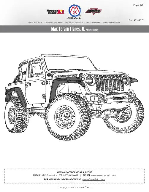
Part #11640.51 460 HORIZON DR. | SUWANEE, GA 30024 | PHONE: 770-614-6101 | FAX: 770-614-6069 | Max Terain Flares, JL Patent Pending ArrayOMIX-ADA® TECHNICAL SUPPORT460 HORIZON DR. | SUWANEE, GA 30024 | PHONE: 770-614-6101 | FAX: 770-614-6069 | Max Terain Flares, JL Patent PendingOMIX-ADA ® TECHNICAL SUPPORT1. Front Flare, LH (1)2. Front Flare, RH (1)3. Rear Flare, LH (1)4. Rear Flare, RH (1)5. Lower Stanchion, RH (1)6. Lower Stanchion, LH (1)7. Light Bracket, RH(1) 8. Support Bracket, RH (1)9. Light Bracket, LH (1)10. Support Bracket, LH(1)11. Daytime Running Light, RH (1)12. Daytime Running Light, LH(1)Components460 HORIZON DR. | SUWANEE, GA 30024 | PHONE: 770-614-6101 | FAX: 770-614-6069 | Max Terain Flares, JL Patent PendingOMIX-ADA ® TECHNICAL SUPPORT1. Flare Clips (36)2. Double Sided Tape (4)3. Trim Foam (4)4. Long M6 Thread Forming Screw (2)5. Medium M6 Thread Forming Screw (2)6. Short M6 Thread Forming Screw (2)7. M8 Oversized Washer (2)8. M6 Button Head Bolt (4)9. M6 Washer (4)10. M6 Flange Nut (4)11. M8 Bolt (4)12. M8 Nut (8)13. M8 Washer (12)Hardware460 HORIZON DR. | SUWANEE, GA 30024 | PHONE: 770-614-6101 | FAX: 770-614-6069 | body as a guide, mark portion of front wheel liner protruding from vehicle body. Using a dremel, or other suitable cutting device, trim the OE front wheel liner along marked lines.460 HORIZON DR. | SUWANEE, GA 30024 | PHONE: 770-614-6101 | FAX: 770-614-6069 | Skip to step 11 if not reusing OE wheel liners.9. Position OE rear wheel liner on vehicle. Using Jeep body as a guide, mark portion of rear wheel liner that protrudes from vehicle body. Using a dremel, or other suitable cutting tool, trim the OE rear wheel liner along marked lines.460 HORIZON DR. | SUWANEE, GA 30024 | PHONE: 770-614-6101 | FAX: 770-614-6069 | 460 HORIZON DR. | SUWANEE, GA 30024 | PHONE: 770-614-6101 | FAX: 770-614-6069 | Max Terain Flares, JL Patent Pending460 HORIZON DR. | SUWANEE, GA 30024 | PHONE: 770-614-6101 | FAX: 770-614-6069 | Max Terain Flares, JL Patent PendingCopyright © 2020 Omix-Ada。
天行者11Android版导航软件上手指南

天行者11Android版快速上手指南免责声明天行者11Android版导航软件的知识产权归属于北京灵图软件技术有限公司。
本产品定位与导航功能使用全球定位系统(GPS),在使用中,GPS定位及导航会存在误差及灵敏度问题,因此而导致的定位不精确及可能出现的导航不准确,与北京灵图软件技术有限公司无关。
受中华人民共和国对于电子地图相关法律的限定,电子地图更新与实际道路变化有可能无法保持同步。
因以上第二条、第三条情形所造成的任何风险和损失,北京灵图软件技术有限公司不承担任何法律责任和赔偿责任。
本文中出现的图片仅供参考,请以实物为准。
1首次使用说明运行程序前,请先确认手机内置存储卡或外部SD卡中存在名为lingtu的文件夹。
利用设备自带的APK安装器安装lingtu文件夹下的SmartGuider.apk文件,即可生成天行者11的快捷图标。
点击手机主屏上的“天行者”图标即可启动天行者导航软件。
温馨提示:天行者启动时,将自动检测手机的GPS是否开启。
如果GPS未开启,程序会提示用户,点击“确定”进入手机“位置和安全”设置界面,请勾选“使用GPS卫星”,然后返回应用程序菜单重新启动天行者即可。
2典型操作下面将以实际操作为例说明【天行者11Android版】的导航步骤:情景:您欲驾车带领朋友去参观北京展览馆,如何使用更简单快捷的方式完成此次导航任务呢?跟我们来吧,让【天行者11Android版】带您走入轻松而愉快的全新旅程吧!步骤一:设定目的地查找您要到达地点名称,选择您所习惯的输入方式,这里以名称搜索为例。
具体方式如下:菜单->当前点->名称搜索(图2.1->图2.2)图2.1图2.2输入“北京展览馆”,点击搜索按钮(如图2.3),选择列表中的“北京展览馆”(如图2.4)。
选择目标地点后会进入地图界面,查看该目标地点的位置(图2.5),点击“”按钮中设为目的地,系统立即为您规划出合理路线(图2.6)。
Haiku 電扇安裝指南说明书
請仔細閱讀並妥善保存本《安裝說明》技術參數檢查風扇標籤,確保電壓正確。
運作電壓直徑 重量 運作頻率 120 伏交流電,單相132 厘米 5 公斤60 赫茲220/240 伏交流電,單相132 厘米 5 公斤50/60 赫茲所需工具• 人字梯• 剝線鉗• Phillips 螺絲批• 六角扳手• 扳手掃描以獲取 Haiku 應用程式網上幫助/support型號: L3127-X5, L3127-X6, FR127C-U1EXX固定支架控制盒電線蓋LED 擴散環固定球及五金件下蓋板飾盒下蓋板圈延長管電機(3)扇葉遙控器五金件盒零件cdef五金件安裝所需的五金件及工具均隨附於五金件盒中。
下圖為五金件的實際尺寸。
固定五金件M8 螺栓M8 墊圈M8 尼龍鎖螺母扇葉五金件(6) M5 螺絲帶齒形墊圈下蓋板五金件固定球及五金件楔子4 毫米自攻螺絲固定球(2)上漆 M3.5 螺絲或電線蓋五金件(4)M4 內六角螺絲3HAIKU BY BIG ASS FANS準備風扇安裝位置安裝過程需要基本的電氣知識。
如您不熟悉電路安裝或當地法例禁止自行安裝,請聯絡持牌電工。
21切斷電源!風扇接線前,請斷開風扇位置的電源!如當地電氣規範對安裝資質有要求,您必須聘請持牌電工安裝風扇。
地線須接駁至電源接地線,且長度必須大於安全電纜。
風扇外部應安裝便於切斷電源的裝置。
必須根據接線規定在固定接線中設置斷電系統。
如直接在建築結構或天花出線盒上安裝風扇,該結構或出線盒必須能夠承托風扇。
4版本 H 08/28/2019 | © 2015 BIG ASS FANS | 版權所有出線盒如當地電氣規範要求風扇必須安裝在天花板出線盒上,該出線盒則必須能夠承托風扇。
如風扇位置未裝有出線盒,應在天花板托樑或橫樑上安裝已妥善接線的出線盒。
混凝土天花板如在混凝土天花板上安裝風扇,請妥善佈線至風扇位置。
使用四枚 Ø 6 毫米 的錨定螺栓(未配備)將固定支架直接安裝在天花板上。
浩瀚自ов特卖 4.0L Jeep Wrangler 空气筒安装说明书

176237Intake Installation InstructionsP/N 9050 (red filter) - P/N 9050B (blue filter)P/N 9050K (black filter)Tools Required:• 5/16” or 8mm Nut driver • 10mm wrench • 10mm socket • 11mm socket • 13mm socket • Ratchet • 3” hole saw • 1/8” Drill bit • Drill• 3/4” Drill bit(2005-2006 model years only)1997-2006 Jeep Wrangler 4.0LYear/Make/Model/EngineParts List 1- Intake tube 1- Air duct tube 1- Heat shield 1- Air filter1- 6” Hose clamp 2- 3” Couplers1- 3”-2 3/4” Reducer coupler 1- 3” Flex coupler1- Velocity stack adapter 1- Edge trim1- 2 3/4” Hose clamp 7- 3” Hose clamps 2- Mini hose clamps 1- 5/8” Hose1- Edge trim- 1/16”1- Grommet 2- M6 bolts 2- M6 washers 2- M6 locknuts1- Firewall duct mount 4- Self tapping screws 1- Convoluted coverFor filter reorders ask at the special order counter of your local parts store or call:1-909-673-9800ask for: P/N HPR9892 (red filter)P/N HPR9892B (blue filter)P/N HPR9892K (black filter)READ THIS BEFORE BEGINNING THE INSTALLATION OF THIS KIT. This is a fresh air intake system which draws cold air from the cowling of your Jeep. In order to access this area, a 3” O.D. hole must be drilled in the firewall. Note that this will increase the noise in the cab of your Jeep, mostly at idle, as the cowl area is the also the source of air for the ventilation system.Step 1Safety first! Before you begin the installation, make sure that the vehicle is in park (or neutral for a manual transmission) with the parking brake set. Disconnect the negative battery terminal and verify that all components that are listed are present. Note: This kit was designed and tested on a stock engine without any custom tuning done to the engine computer. Removing the battery cable may erase the programmed radio stations. The anti-theft code will need to be entered into some radios after the battery cable is connected. The anti-theft code can typically be found in the owner’s manual or at your local dealership.176237Step 2Loosen clamp at throttle body. Remove the crank case vent hose from 90° fitting. If present, disconnect the IAT electrical connector. Unclip air box cover. Lift entire assembly from engine.Step 4Follow the negative battery cable to where it mounts to the firewall and remove the bolt.Step 3Remove the air filter and locate the three mounting nuts on the inside of the fender well. Remove the nuts and remove the air box base from the engine compartment. The pictured components will now be out of the engine compartment.Step 7Install the 1/16” edge in area shown with the arrow. This may require trimming to the correct length. Install the edge trim around the edge of the heat shield. This may require trimming to the correct length.Step 8Place the velocity stack adapter in the heat shield and install the supplied flex coupler making sure the coupler is pushed completely against the heat shield. Once the adapter and coupler are tight against the heat shield, tighten the clamp. Install the 3” coupler and two clamps completely over the tube that is welded onto the heat shield.Step 5Remove cable from the factory harness by cutting the tape on the wire sheath and sliding it out. Install the supplied convoluted tubing over the cable. Locate the pictured bolt, just to the left of the two wire harness plugs and remove it. Route the cable behind the cylinder head. Install the bolt as shown in the picture with thestar washer between the body and the negative cable. Tighten the bolt.Step 6Install the reducer coupler on the throttle body and secure the boot in place. Install a second clamp butdo not tighten at this time.Step 9Remove the upper radiator bolt and the strut brace bolt. These will be reused in the next step.Step 10Install the heat shield making sureto place the strut thru the cut outin the heat shield. Once in place,fasten it securely in place with thesupplied hardware and the hardwarethat was removed in Step 9.Step 11If your vehicle came with an IAT sensor, you willneed to drill a hole in the intake to install it. Removethe sensor from the stock intake tube and removethe o-ring from the sensor. Determine the bestlocation for the sensor in the area shown in thepicture, making sure that it will not interfere withany other components and the wiring harnesswill reach. Drill a ¾” hole at the marked location(remove all burrs and clean out any metal shavingsbefore continuing.) Install the supplied grommetand insert the IAT sensor.Step 12Install the intake tube and once in desired position fasten it securely in place. If the vehicle has an IAT sensor, reconnect the sensor at this time.Step 13Install the air duct tube with the firewall mount on the end of the tube. Hold the air duct tube up as high as possible against the cowl rubber molding. Ensure that the bottom of the mount is higher than the bend in the firewall, which is the base of the cowl area. Mark along the edges of the duct mount so that you can replace it in the next step without theintake tube in place. DO NOT CUT INTO THE AREA BELOW THE BEND!Step 14With your duct mount located with the marker, you can take the assembled intake tube off of the vehicle for now. At this point mark the center of the mount to locate the 3” hole. Before drilling, make sure the top ofthe hole will be no more than 1/2” below the cowl molding. Find the center of your 3” hole for your hole sawso that you drill in the proper place. MAKE SURE THE TOP OF THE HOLE WILL BE NO MORE THAN 1/2”BELOW THE COWL MOLDING.176237© 2015 SPECTRE PERFORMANCE Made in China(909) 673-9800176237Step 15In this step, you will be using a 3” hole saw to make a hole in the firewall for the fresh air source. AGAIN, VERIFY THAT THE TOP OF THE HOLE WILL BE NO MORE THAN 1/2” BELOW THE COWL MOLDING. Move and secure all wiring away from this area. A bungee cord can be used to keep the wiring away from the area to be drilled. If it helps, you can remove the cowling at the base of the windshield to see where you will be drilling. DO NOT CUT OR DRILL INTO THE AREA BELOW THE BEND OF THE COWL. Using the mark you made from the previous step, drill through the firewall into the cowl area. Use care and remove the piece of firewall as the edges are HOT AND VERY SHARP! NOTE: For later model years the firewall is slightly different than shown in the pictures. Also, the wire harness bracket may differ from the one in the pictures and you may have to trim, bend or move this bracket to clear the intake tube once it is in place.Step 16Install the suppliedfirewall duct mount and once it’s in place, secure with the four supplied self-tapping screws.Step 18Install the air duct tube into the firewall duct mount coupler first then align it with the heat shield. Slide the coupler on the heat shield end onto to the air duct tube making sure to equally space the coupler on the air duct tube and heat shield tube.Step 17Install the supplied coupler on the firewall duct mount and secure with supplied clamp. Install a second clamp but do not tighten it at this time.Step 19Install the supplied crank case vent hose and fasten it securely in place.Step 21Make sure that all clamps and hardware are fullytightened. Reconnect the battery cable, start the vehicle and let it warm up. Shut off and inspect the installation once more for any loose clamps, wires, or hardware. Test drive & enjoy! Your installation is now complete. Periodically check all clamps and brackets.shield end onto to the air duct tube making sure to equally space the coupler on the air duct tube and heat shield tube.Step 20Install the filter and securely fasten to thevelocity stack adaptor.。
ALIENWARE M14x MOBILE 手册说明书
3
目录
第 3 章:使用膝上型计算机 . . . . . . . . . . . . . . . . . . . . . . . . . . . . . . . . . . . . . . . . . . . . . . . . . . . . . . . . . . 39 Alienware 命令中心 . . . . . . . . . . . . . . . . . . . . . . . . . . . . . . . . . . . . . . . . . . . . . . . . . . . . . . . . . . . . . . 40 连接外部显示器. . . . . . . . . . . . . . . . . . . . . . . . . . . . . . . . . . . . . . . . . . . . . . . . . . . . . . . . . . . . . . . . . . 40 使用无线控制功能 . . . . . . . . . . . . . . . . . . . . . . . . . . . . . . . . . . . . . . . . . . . . . . . . . . . . . . . . . . . . . . . 44 电池组 . . . . . . . . . . . . . . . . . . . . . . . . . . . . . . . . . . . . . . . . . . . . . . . . . . . . . . . . . . . . . . . . . . . . . . . . . . 45 电源管理 . . . . . . . . . . . . . . . . . . . . . . . . . . . . . . . . . . . . . . . . . . . . . . . . . . . . . . . . . . . . . . . . . . . . . . . . 46 nVidia Optimus 技术 . . . . . . . . . . . . . . . . . . . . . . . . . . . . . . . . . . . . . . . . . . . . . . . . . . . . . . . . . . . . . 48 自由下落传感器. . . . . . . . . . . . . . . . . . . . . . . . . . . . . . . . . . . . . . . . . . . . . . . . . . . . . . . . . . . . . . . . . . 50 FastAccess 人脸识别(可选) . . . . . . . . . . . . . . . . . . . . . . . . . . . . . . . . . . . . . . . . . . . . . . . . . . . . 50 配置 BIOS . . . . . . . . . . . . . . . . . . . . . . . . . . . . . . . . . . . . . . . . . . . . . . . . . . . . . . . . . . . . . . . . . . . . . . . . 51
Halsey Taylor 全浸入壁挂无障碍水冷器安装指南说明书
A 7" 178mm B
WALL OPENING
18" 457mm 17 1/8" 435mm WALL OPENING 1460"6mm
FOUNTAIN FINISHED WALL
12" 305mm
MINIMUM DEPTH
6 1/16" 154mm
BACK WALL LINE
24" 610mm
50 1/4" 1276mm
PAGE 3
97884C (Rev. C - 09/16)
RC8AQ*A RC12AQ*A
Note: Danger! Electric shock hazard. Disconnect power before servicing unit.
USES HFC-134A REFRIGERANT
INSTALLATION INSTRUCTIONS RC MODELS DRINKING FOUNTAIN
6. Install wall frame assembly in wall opening with front edge of frame flush with finished wall face. Secure frame through holes in top and sides to wall support members with 5/16” diameter fasteners (bolts or lag screws) as required by wall constructions. (14) bolts/screws required. CAUTION: DO NOT USE LESS THAN REQUIRED QUANTITY AND SIZE (DIAMETER) OF FASTENERS.
天行者x7 gps行车纪录器 说明书
16
Innovative Personal Driving Recorder
■X7操作影像( 實際日間影像 與 夜間影像)
按鍵功能
IconΒιβλιοθήκη 名字 關閉視窗 設定 拍攝 列印 備份 速度 音量 播放 倒退 暫停 停止 移動影片到前一節 移動影片到後一節 開啟
4. 電腦辨識後,請點選。
5. 錄製的數位影像會列於資料夾中。 6. 點選X7 manager.exe。 7. 檔 案 開 啟 後 , 您 可 觀 看 影 片 或 對 紀 錄 器 做 設 定 。 8. 觀看影片請點選右欄 FileList 的影片紀錄。
8.如需刪除資料需用managex.exe 工具圖框內中格式化的方式,將整個資料清空完全刪 除。
客製 連結 X7 於電腦時,使用者可針對喜好做個人化項目設定。
節源指示燈 X7 經由指示燈顏色顯示駕駛狀態和能源消耗。省油時顯示藍燈,耗油時顯示紅 燈,提供您駕駛時的安全及提醒燃油耗能狀態。
7
5. 安裝說明
為了安全並完整安裝,請按照如下說明: 1. 使用 USB 裝置連結 X7 於電腦,第一次安裝需要 1 ~ 2 分鐘請耐心等待,一旦連結後打 開 X7 管理系統點擊齒輪工具圖案”設置”,再點擊”時間設定” ,同步正確的數據和時間。 安裝產品前至少要先做第一次 GPS 時區同步校正設定
4. 請按 X7 上的播放按鍵。
5.播放順序 為時間點最接近之緊急事件優先。 時間點最早的緊急事件播放完畢後, 接續回播一般連續事件。 6.播放時,電源燈會熄滅,節源燈顯示黃燈並閃爍。 7.事件紀錄的數據會依照時間排列順序,當您再次按下播放鈕時,會播放下一段影 片。 8.播放完所有的影片後,X7 會自動切換成錄影模式。
天行者X-8安装手册(简体中文翻译版)
Skywalker X-8 Installation Manua天行者X-8安装手册(汉化版)翻译---- China·天奇Thank you for Purchasing the Sky- walker X-8 Plane. The skywalker X-8 is designed for First-Person-Vision(FPV) application specifically.感谢您购买天行者X-8飞翼型飞机。
天行者X-8是专为第一人称飞行(FPV)而设计的。
Technical parametersWingspan:2120mm weight 880G motor 2820 KV730 speed regulator 60A battery pack 4S8000MAH propeller 12X6~13X8技术参数:翼展:2120mm 空机重量880克电机2820 kv730 电子调速器60A电池组4s 8000mah螺旋桨12x6 ~ 13x8Take-off weight :3200G设计最大起飞重量:3200gKIT version configuration:Fuselage, wing, winglet , tube, accessories bag, sticker包版本的配置:机身,机翼,翼梢小翼,碳纤维管,配件袋(包含,胶水、拉杆、螺丝、层板、舵角、舵机延长线、强磁铁),贴纸Parts Listing零件清单:如图1AssemblyGlue the winglet layers, spread the glue evenly over the wing and both sides of the layers ( the layer marked with T board belongs to parts of the main wing )安装说明:翼梢小翼层胶,涂胶均匀,两侧翼的层(层在标有T板属于主翼部分)2Wait for 5 minutes to allow glue to dry until it is non-sticky, then they can be glued in alignment , 等待5分钟让胶干直到不粘腻的,然后他们可以粘在对准3Glue the hatch magnets , after compressing the magnet tightly, fix them with CA glue. 胶舱口的磁铁,磁铁牢牢固定压缩后,用快干固定胶如401胶水或502胶水。