HQA-N200石英挠性加速度传感器说明书
HQA-T160石英挠性加速度传感器
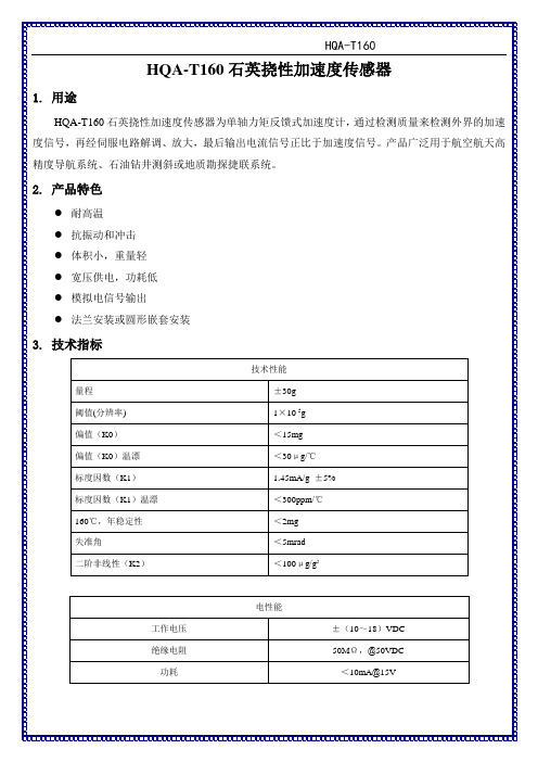
外形尺寸:60×41×35mm传感器质量:≤350克
6.安装要求
传感器安装时,应避免大力磕碰。
7.注意事项
使用时,轻拿、轻放传感器;千万不能摔、掉在地上;在通电前,一定要检查接点是否准确,地线连接是否正常。
传感器在运输时应小心轻放。每个产品应装在包装盒内,装盒前产品应用薄膜塑料袋包好,再装入盒内。传感器的接插件应有塑料保护帽,盒内空隙处用泡沫塑料填充。
传感器校准前,供电电源的电压应用精度高于0.1%的数字电压表检查,给传感器加电时,切勿接错电源。
产品应放在温度为+10℃~+30℃,湿度为40%~70%通风良好的库房中,库房中不允许同时存放酸、碱等化学药品及有害气体(氯、氨、煤烟及其他)进入。
<100μg/g²
电性能
工作电压
±(10~18)VDC
绝缘电阻
50MΩ,@50VDC
功耗
<10mA@15V
环境条件
正弦振动
30g 0~peak,(30~2000)Hz
随机振动
20gram,(15~500)Hz
冲击
1000g,0.5msec,half sine
工作温度
(-40~160)℃
4.接点分配及定义
HQA-T160石英挠性加速度传感器
1.用途
HQA-T160石英挠性加速度传感器为单轴力矩反馈式加速度计,通过检测质量来检测外界的加速度信号,再经伺服电路解调、放大,最后输出电流信号正比于加速度信号。产品广泛用于航空航天高精度导航系统、石油钻井测斜或地质勘探捷联系统。
2.产品特色
耐高温
抗振动和冲击
体积ቤተ መጻሕፍቲ ባይዱ,重量轻
宽压供电,功耗低
模拟电信号输出
加速度传感器手册
50, 100, 200, 500, 2.0 ~ 0.10 mV/g
2000, 6000
50, 100, 200, 500, 2.0 ~ 0.10 mV/g
2000, 6000
50, 100, 200, 500, 2.0 ~ 0.10 mV/g
wwwsensorwaycn板载式加速度传感器型号特点应用量程g灵敏度响应频率激励电压针脚或贴片焊接针脚或贴片焊接贴片焊接贴片焊接温度补偿温度补偿贴片焊接贴片焊接贴片焊接板载式焊接针脚焊接40030mvg40030mvg30060mvg30060mvg180024mvg180024mvg804mvg100010mvg10004mvg153mvg075025mvg11vg04khz04khz02khz05khz03khz03khz015khz015khz015khz24khz1010khz142hz210vdc210vdc210vdc210vdc210vdc210vdc5vdc832vdc832vdc3355vdc3355vdc501005010020050020006000251020501002005001002005002000600010025102050100200251020501002002510205010025102050100251020501002003022302830313038305230583255a45034655832三轴834三轴minisense100量程可根据客户要求任意选择10vdc激励电压放大输出带放大动态测量传感器选型手册精量电子深圳有限公司wwwsensorwaycn2550100250500三轴低成本状态检测板载式焊接三轴低成本状态检测非放大型加速度传感器37003801a52型号特点应用量程g灵敏度响应频率激励电压20006000251020501002005002000502005002000015008mvg12010mvg20015mvg07khz04khz07khz210vdc210vdc210vdc气体阻尼冲击测试结构测试螺柱安装侧面碰撞测试52m3052m504061ab6264液态阻尼saej211认证小尺寸大量程小尺寸铝外壳头部碰撞假人碰撞假人碰撞经典外形假人碰撞经典外形501002505001000200050200500200050500100020007505010020050020006000501002005002000600030008mvg20015mvg20015mvg035mvg20010mvg20010mvg010khz07khz07khz03khz07khz10vdc210vdc210vdc210vdc210vdc64b64c
SNDH -H Series 磁感应速度传感器产品说明书

SNDH-H SeriesHall-Effect Speed SensorsDESCRIPTIONThe SNDH-H Series Hall-Effect Speed Sensors use a magnetically biased Hall-effect integrated circuit to accurately sense movement of ferrous metal targets. The specially designed IC (integrated circuit) and a permanent magnet are sealed in rugged, probe-type packages.The flux density of the permanent magnet alters when approached by ferrous metal. This is detected by the Hall ICs. If the sensor is positioned at the circumference of a revolving gear wheel, for example, it detects the teeth and tooth spaces, supplying a digital pulse output with frequency proportional to gear wheel speed.Optimum performance is dependent upon variables whichmust be considered in combination: target material, geometryand speed, sensor/target gap, and environmental temperature.FEATURESSolid state, non-contacting Hall-effect magnetic sensingallows the device the ability to sense through dust, dirt anddebris, enhancing reliability and product lifeAir gap up to 2,5 mm [0.098 in] allows sensor to be up to 2,5mm away from targetHigh frequency switching capability (to 15 kHz) allows thedevice to handle high RPMs (SNDH-H3L-G01, SNDH-H3C-G03, SNDH-H3C-G05, SNDH-H3C-G06)O-ring seal allows device to be sealed into housingsTwo housing materials allow flexibility within the application:stainless steel (corrosion and rust resistant): SNDH-H3L-G01; plastic: SNDH-H3C-G03, SNDH-H3C-G04, SNDH-H3C-G05 and SNDH-H3C-G06, SNDH-H3P-G01Various probe lengths (20,3 mm [0.80], 24 mm [0.94 in]27,5 mm [1.08], 40 mm [1.57 in], 46 mm [1.81 in], 67 mm[2.64 in] simplify use within the applicationHigh operating temperature [-40 C to 150C (-40F to302 F)] (SNDH-H3C-G03, SNDH-H3C-G05, SNDH-H3C-G06) allows the device to be used in high temperatureapplications (e.g., engines)Digital current sinking output (open collector) simplifieselectrical interfacing to control systemsMultiple connector options (Bosch 928000453, Delphi-Packard Metripak 150.2 Type 101, Deutsch DT06-3S)simplify installationOmnidirectional capability eliminates the need to align thesensor to the target, allowing the user to simply bolt thedevice (SNDH-H3C-G0, SNDH-H3L-G01)Zero speed versions indicate that the rotation has stopped,allowing the device to work at extremely low RPMs (SNDH-H3L-G01, SNDH-H3C-G04, SNDH-H3P-G01)Stable performance over temperature range and airgaprangePOTENTIAL APPLICATIONSTransportationEngine camshaft and crankshaft speedTransmission speedVehicle speedWheel speedPump speedMotor speedIndustrialFlow meters and flow turbinesPump speedMotor speedSNDH-H SeriesNotes:1.Short circuit protected.2 /sensingHall-Effect Speed Sensors SNDH-H3L-G01SNDH-H3C-G03Honeywell Sensing and Control 3SNDH-H SeriesFigure 1. Mounting Dimensions and General Mounting Geometry (For reference only: mm [in].) (continued) SNDH-H3C-G04SNDH-H3C-G054 /sensingHall-Effect Speed Sensors SNDH-H3C-G06SNDH-H3P-G01Honeywell Sensing and Control 5Sensing and Control Honeywell1985 Douglas Drive NorthGolden Valley, MN 55422 /sensing 005933-2-ENFebruary 2012Copyright © 2012 Honeywell International Inc. All rights reserved.WARNINGWARRANTY/REMEDYHoneywell warrants goods of its manufacture as being free of defective materials and faulty workmanship. Honeywell’s standard product warranty applies unless agreed to otherwise by Honeywell in writing; please refer to your order acknowledgement or consult your local sales office for specific warranty details. If warranted goods are returned to Honeywell during the period of coverage, Honeywell will repair or replace, at its option, without charge those items it finds defective. The foregoing is b uyer’s sol e remedy and is in lieu of all other warranties, expressed or implied, including those of merchantability and fitness for a particular purpose. In no event shall Honeywell be liable for consequential, special, or indirect damages.While we provide application assistance personally, through our literature and the Honeywell web site, it is up to the customer to determine the suitability of the product in the application.Specifications may change without notice. The information we supply is believed to be accurate and reliable as of this printing. However, we assume no responsibility for its use.WARNINGMISUSE OF DOCUMENTATIONThe information presented in this product sheet is forreference only. Do not use this document as a productinstallation guide.Complete installation, operation, and maintenanceinformation is provided in the instructions supplied witheach product.Failure to comply with these instructions could result in death or serious injury.SALES AND SERVICEHoneywell serves its customers through a worldwide network of sales offices, representatives and distributors. For application assistance, current specifications, pricing or name of the nearest Authorized Distributor, contact your local sales office or:E-mail:*********************Internet: /sensingPhone and Fax:Asia Pacific +65 6355-2828+65 6445-3033 FaxEurope +44 (0) 1698 481481+44 (0) 1698 481676 FaxLatin America +1-305-805-8188+1-305-883-8257 FaxUSA/Canada +1-800-537-6945+1-815-235-6847+1-815-235-6545 FaxMouser ElectronicsAuthorized DistributorClick to View Pricing, Inventory, Delivery & Lifecycle Information:H oneywell:SNDH-H3C-G03SNDH-H3C-G04SNDH-H3L-G01SNDH-H3P-G01SNDH-H3C-G06SNDH-H3C-G05。
柏林精密传感器(Balluff)系列加速度传感器产品介绍说明书

Sensor systems for turbomachineryAccelerometers with external charge amplifiersCA202C A280C A 306C A 134C A901100 pC/g (400 g)-55 to 260o C 0.5 to 8000 Hz100 pC/g (500 g)-55 to 260o C0.5 to 10000 Hz 50 pC/g (100 g)-55 to 500o C 5 to 3000 Hz 10 pC/g (500 g)-196 to 500oC 0.5 to 6000 Hz 10 pC/g (500 g)-196 to 700o C3 to 3700 HzTransducer Cable Softline, armouredEC 112 - MI EC 069 - MI MI, overbraided EC 119 (390) - softline, armouredEC 222 - softlineMIEC 119 (390)For heavy-duty gas and steam turbines. Piezoelectric accelerometer for use over an extended temperature range.For heavy-duty and aero-derivative gas turbines, gearboxes, compressors and marine applications. Multi-purpose, compact piezoelectric accelerometer for use over an extended temperature range.For aero-derivative and industrial gas turbines. Piezoelectric accelerometer for use at high temperatures. Similar parts are standard with numerous OEMs.For cryogenic applications and gas turbines. Piezoelectric accelerometer for use over a very wide temperature range.For heavy-duty gas turbines. Piezoelectric accelerometer for use at extreme temperatures. Similar parts are standard with numerous OEMs.Galvanic separationExtension cable Conditioner Cable EC 153 - softline K2xx (3xx)2 or 3-wire transmissionIPC 704 in ABA 160GSI 127 galvanicseparation unit GSI 127• Power supply for 2-wireand 3-wire transmissionsystems installed inpotentially explosive environments• µA to mV conversion for long distance (2-wire)signal transmission, up to 1000 m• V to V conversion for short distance (3-wire) signal transmission• Galvanic separation, 4 kV RMS• High rejection of frame voltage• DIN rail mounting • Ex certified versionsIPC 704 conditioner • Signal conditioner for CA and CP sensors • Configurable high-pass and low-pass filters, freq. range 0.5 Hz to 20 kHz • Optional integrator for a velocity output signal • Optional 2-wire current or 3-wire voltage transmission • Ex certified versionsABA 1xx industrial housings • Protection againstmechanical damage, waterand dust (IP66 rated)• Several models and configurations, suitable for1 up to 10 conditioners • Diecast polyester or aluminium enclosure, fully insulated and corrosion resistant• Ex certified versionsEC 153 - softline EC 153 - softline Softline, armouredAccelerometers with built-in or attached electronicsCE134CE281CE311CE68SE125 µA/g (400 g)-55 to 350o C5 to 10000 Hz10 µA/g (200 g)-55 to 260oC3 to 10000 Hz50 µA/g (40 g)-55 to 125o C2 to 8000 Hz100 mV/g (80 g)-55 to 120o C0.5 to 9000 Hz2 mA/g (4 g)0 to 75o C0.2 to 750 HzTransducer Cable Extension cableEC 319 - softlineSoftline, armouredSoftlineEE 139Softline, armouredSoftline, armouredEE 143EC 175EC 175ThreadedBayonetFor heavy-duty gas turbines, aero-derivative gas turbines and compressors.Piezoelectric accelerometer with attached electronics, for use over an extendedtemperature range.For gearboxes, compressors, pumps and fans. Compact piezoelectric accelerometerwith attached electronics, for use over an extended temperature range.For heavy-duty gas and steam turbines. Piezoelectric accelerometer with built-inelectronics, for use in industrial environments.For auxiliary machines. Multi-purpose, compact piezoelectric accelerometer withbuilt-in electronics, for use in industrial environments.For slow-speed rotating machines, hydro turbines and fans. High-sensitivitypiezoresistive accelerometer.Galvanic separationJunction box CableK2xxJB 116 (JB 105)K2xxJB 116 (JB 105)Softline, armouredSoftlineSoftlineSoftline, armouredJB 1xx junction boxes• Protection againstmechanical damage, waterand dust (IP65 rated)• Several models available• Diecast polyester oraluminium enclosure, fullyinsulated and corrosionresistant• Ex certified versions2-wire transmission2-wire transmissionGSI 127 galvanicseparation unitGSI 127• Power supply for 2-wireand 3-wire transmissionsystems installed inpotentially explosiveenvironments• µA to mV conversion forlong distance (2-wire)signal transmission, upto 1000 m• V to V conversion for shortdistance (3-wire) signaltransmission• Galvanic separation,4 kV RMS• High rejection offrame voltage• DIN rail mounting• Ex certified versionsCP103C P 235C P211C P50x 232 pC/bar (20 bar)Overload up to 250 bar-196 to 700o C 2 to 10000 Hz 750 pC/bar (20 bar)Overload up to 100 bar-55 to 520oC 2 to 10000 Hz 25 pC/bar (250 bar)Overload up to 350 bar-196 to 777o C 2 to 15000 Hz 90 pC/barOverload up to 100 bar -70 to 560o C 0.5 to 20000 Hz MI MI MI MI, overbraidedEC 153EC 119 (390)Dynamic pressure sensors for combustion monitoringTransducerCable Very high temperature dynamic pressure sensor. Similar parts are standard with numerous OEMs.High temperature, very high sensitivity dynamic pressure sensor. Similar parts are standard with numerous OEMs.High-temperature dynamic pressure sensors. The GaPO 4 (gallium phosphate) piezoelectric material used ensures outstanding thermal behaviour (no pyroelectricity) and virtually constant sensitivity. Similar parts are standard with numerous OEMs. An active acceleration compensation is available.Very high temperature, compact dynamic pressure sensor. Mostly used for laboratory measurements in extreme environments.Extension cable Galvanic separationConditioner Cable K2xxSoftline Softline, armoured 3 x IPC 704 in ABA 151IPC 704 in ABA 1506 x IPC 704 in ABA 153IPC 704 conditioners• Signal conditioner for CA and CP sensors• Configurable high-pass andlow-pass filters, freq. range 0.5 Hz to 20 kHz • Optional integrator for avelocity output signal• Optional 2-wire current or 3-wire voltage transmission• Ex certified versions 2-wire transmissionGSI 127 galvanicseparation unitGSI 127• Power supply for 2-wire and 3-wire transmission systems installed in potentially explosive environments• µA to mV conversion for long distance (2-wire) signal transmission, up to 1000 m• V to V conversion for short distance (3-wire) signal transmission• Galvanic separation,4 kV RMS • High rejection of frame voltage• DIN rail mounting • Ex certified versionsProximity probes for all displacement measurements8 mV/µm or 2.5 µA/µm (2 mm range)-40 to 180o C 5mm Ø tip8 mV/µm or 2.5 µA/µm (2 mm range)4 mV/µm or 1.25 µA/µm (4 mm range)-40 to 180o C 8.2mm Ø tip 4 mV/µm or 1.25 µA/µm (4 mm range)-25 to 140oC12.7mm Ø tip Pressure proof, 100 bar (tip)4 mV/µm or 1.25 µA/µm (4 mm range)-25 to 140o C 12.7mm Ø tip Pressure proof, 100 bar (tip)Reverse mount 8 mV/µm or 2.5 µA/µm (2 mm range)4 mV/µm or 1.25 µA/µm (4 mm range)-40 to 180o C8.2mm Ø tip Reverse mount 1.33 mV/µm or 0.417 µA/µm (12 mm range)-40 to 180oC 18mm Ø tip1.33 mV/µm or 0.417 µA/µm (12 mm range)-25 to 140o C 25 mm Ø tip Pressure proof, 100 bar (tip)Transducer Cable PA 151Softline KS 107SoftlineSoftline Probe adaptor SoftlineSoftline Softline T Q 401T Q402T Q 422T Q432T Q 412T Q 403T Q423JB 118SG 101 (102)Junction box / protection Galvanic separationConditioner Cable K2xx (3xx)EA 401 (402, 403)EA 401 (402, 403)Flexible conduitMovable, armoured IQS 45x in ABA 1503 x IQS 45x in ABA 1516 x IQS 45x in ABA 153SoftlineDisplacement range from 0.2 to 12 mm. For measuring relative vibration, axial thrust, differential expansion and phase reference on turbomachinery. Transmissiondistances over 1000 m. Various body lengths and tip diameters are standard. High pressure versions, reversible mounting, armoured cable protection and probe adapters are available. These products are compliant with API 670 standards.IQS 45x conditioners• Signal conditioner forTQ 4xx probes • Optional 2-wire current or 3-wire voltage transmission • Diecast aluminium enclosure• Ex certified versions2 or 3-wire transmission GSI 127 galvanicseparation unit GSI 127• Power supply for 2-wireand 3-wire transmission systems installed in potentially explosive environments • µA to mV conversion for long distance (2-wire)signal transmission, up to 1000 m• V to V conversion for shortdistance (3-wire) signal transmission• Galvanic separation,4 kV RMS • High rejection of frame voltage • DIN rail mounting• Ex certified versionsVE210E W140L S 12020 mV / mm/s(1000 mm/s)-29 to 204o C 10 to 1000 Hz 50 mV / mm/s 50 µA / mm/s (100 mm/s)-25 to 80oC0.5 to 400 Hz20 mV / mm/s(1000 mm/s)-29 to 121o C10 to 1000 Hz0.2 to 2 mm ice -55 to 120oC2 to 33 mm -15 to 125o CEC 119 - softline, armoured EC 440 - 3-wire (voltage transmission)EC 439 - 2-wire (current transmission) Velocity sensorsIce detection systemAir gap monitoring system Transducer Extension cable ED 121 - softline ED 120 - softlineC V213C V214For low-speed machines such as hydroelectric turbomachinery. Low-speed velocity transducer with a stainless steel body and a protection rating of IP68, ideal for moist or corrosive environments. The body of the VE 210 transducer includes the signal conditioner electronics.For hydro and steam turbines. Low-speed velocity transducers, resistant to dust and moisture (IP64 rated).For large hydroelectric generators. Monitors the air gap between the rotor and stator.For all gas turbines. Detects initiation of ice on gas turbine inlets. Used by turbine de-icing systems to optimise the use of bleed air.Controller Junction box Conditioner Cable ILS 730 in ABA 151JB 116 (105)K2xx DIC 413K509 (709)ILS 730 conditioner• Signal conditioner for LS air gap transducer• Three voltage-based outputs (pole profile, rotor profile, min. gap); oneselectable 4-20 mA output (factory setting)• Diecast aluminiumenclosure 2-wire transmissionComplete monitoring solutionsOne sourceRequest a complete solution from Meggitt. In our facility in Switzerland more than 600 employees combine their expertise and commitment to design and build all parts of our system: sensors for harsh environments (measuring vibration, dynamic pressure, displacement, blade tip clearance, etc), high performance monitoring systems and software. Our sales and support network delivers outstanding service worldwide.Plant asset management systemTurbine health management systemPiezoelectric Dynamic pressure Proximity Piezoelectric MicrowaveCase studiesHeavy-duty gas turbine: Siemens SGT5-4000F Combustion and vibration monitoring (VM600 with CP and CA sensors)The SGT5-4000F (V94.3A) dry low-NO X gas turbine (GT) is one of the most powerful in operation, designed for large-scale applications with more than 280 MW ISO output. Meggitt is the exclusive supplier of protection and monitoring equipment for this GT, Siemens’ proven workhorse, with more than three hundred units in operation worldwide.One of the major industrial challenges with heavy-duty GTs is to combine the highest possible efficiency with extremely low NO X emissions and lowcombustion temperatures. Measuring the dynamic pressure at different locations in the combustor is a proven way to control combustion. Thus, pulsation monitoring systems are essential during both tuning and operation.The sensors and monitoring equipment provided by Meggitt allow Siemens to control combustion parameters such as fuel injection, which leads to extremely low emissions, reduced fuel consumption and long intervals between major inspections. Our sensing and monitoring systems on the SGT5-4000F include extreme temperature dynamic pressure sensors (CP 216), high sensitivity piezoelectric accelerometers (CA 201 and CA 901) and protection and monitoring systems (VM600).Meggitt is proud to have contributed to making theSGT5-4000F one of the most efficient GTs availablefor power generation applications.Hydro turbine-generator: Cahora Bassa hydro power plant (Mozambique)Air gap and vibration monitoring (VM600 with CE, LS, SE and TQ sensors)The Cahora Bassa dam on the Zambezi river was completed in 1975 and renovated in 2003; its plant comprises five Francis turbines with a total power of 2.1 GW. Within the renovation project, Alstom selected Meggitt to provide machinery vibration and generator air gap sensors with a networked protection and condition monitoring system. Condition monitoring of hydroelectric generators is critically important, especially monitoring the distance between the rotor poles and the stator walls, called air gap. To increase efficiency in generators, the air gap is reduced to a minimum. However, both the stator and the rotor on large hydroelectric machines can be quite flexible and their shape and location are affected in operation by centrifugal, thermal and magnetic forces. This means that the air gap can only be effectively measured while the generator is in service. In the absence of effective monitoring, efficiency would decrease and potential machine damage could occur.In Cahora Bassa, each generator is equipped with a capacitive air gap measurement system (4x LS 120 sensors with ILS 730 conditioners). This on-line system is used when the machine is rotating and withstands the extremely high magnetic fields in the air gap. Furthermore, each turbo generator has piezoresistive, low-noise, low-frequency SE 120 accelerometers to measure the bearings’ absolute vibrations. On rotating parts, the relative shaftSGT5-4000F (© Siemens AG)Balance-of-plant: Yonghung thermal power plant (South Korea)Proximity, displacement and vibration monitoring (VM600 with TQ and CE sensors)Yonghung is the largest coal-fired power plant in South Korea. Each 870 MW supercritical unit is designed for variable pressure operation at 3600 RPM and 560°C. Yonghung is designed with the philosophy of preserving the environment using two stage combustion with low-NO X burners followed by selective catalytic reduction.To ensure efficient plant operation and to achieve their environmental objectives, Yonghung TPP has 22 VM600 racks that provide over 800 dynamic measurement points on units 3 and 4. These Meggitt systems secure and monitor a variety of machines for the steam turbine and the balance-of-plant in Yonghung, such as BFP (boiler feed pump) turbines, BFP motors, forced daft fans, primary air fans, condensate pumps (booster and water), blowers and air compressors.At Yonghung TPP, Meggitt’s highly reliable sensors for harsh environments measure a range of vibration and displacement characteristics. Proximity probes (TQ 402) and piezoelectric accelerometers (CE 680) measure shaft position, relative shaft vibration (x-y), rotational speed of shaft and bearing broad-band absolute vibration. Furthermore, Vibro-Meter sensors on the primary air fan enable the pre-heater system to use hot air to remove moisture from coal before the combustion process, which reduces NO X emissions. The machinery protection functions and the condition monitoring functions of the VM600 system then process the signals and provide a complete data overview. This is necessary to maintain an efficient plant operation through diagnostics and plant health management.vibration is performed by the TQ 402 proximity probes. The stator’s structural vibrations are monitored with compact piezoelectric accelerometers (CE 680). Coupled with our sensors, the VM600 protection and condition monitoring system ensures the highest safety level during operation.Early detection of air gap anomalies using the equipment supplied by Meggitt enables condition monitoring of Cahora Bassa hydroelectric generators. As a result, plant efficiency is optimised, generator damage can be avoided and operators can more efficientlypredict and plan maintenance outages.Cahora Bassa HPP (courtesy of Hidroelectrica de Cahora Bassa)Yonghung TPP (courtesy of Vibro Korea)。
华氏12012线性4-20mA输出温度传感器说明书

To Order (Specify Model Number)
Model No.
Price Description
Applications
OS1611(*)-(**) OS1711(*)-(**) OS1811(*)-(**)
$ 930 1125 1850
Remote IR sensing head and electronics
Shown smaller than actual size.
OS1700 Series sensor with integral electronics.
ߜ Linear 4 to 20 mA Output
ߜ Simple 2-Wire Installation
ߜ 10 to 40 Vdc Power Operation
ߜ 3 Models to Choose From
ߜ 6 Infrared Spectral Responses
OS1800 Series sensor with integral electronics/display.
OS1600 Series OEM style sensor and remote electronics.
J-95
RUGGED!
INDUSTRIAL!
Rear view showing sensor.
J
OS1811-112-S, $1600, shown actual size.
signal allows the sensor to be interfaced with a variety of remote devices: indicators, controllers, recorders, and/or computers, etc.
恒温传感器数据手册说明书

Temperature transmitter(1)All the accuracies indicated in this technical datasheet were stated in laboratory conditions, and can be guaranteed for measurements carried out in the same conditions, or carried out with calibration compensation.(2)Calculated values.Features•Configurable ranges from 0 to 50°C(ambient model) and from -100 to 400°C (model with terminal block)•24 Vdc/Vac power supply•Display of the minimum andmaximum values and trend indicator •“¼ turn” system mounting with wall-mount plate4 wires analogue outputs 0-5/10 V or 0/4-20 mA Possibility of a second remote probe on terminal block ABS V0 IP65 housing, with display2 relay outputsTM 210----Power supply/Output B: 24 Vac/Vdc Part numberDisplay O: with displayType of probeS: Ambient + Pt100 terminal block B: Two Pt100 terminal blocksExample: TM210 – BOS – RTemperature transmitter, ambient probe and relay outputs.Relay outputsRTM210 transmitter can measure up to two temperatures (temperature 1 and temperature 2). When two temperature probes are connected, the transmitter can display the difference between both measured temperatures. It can also calculate different parameters in psychrometry thanks to the KHP psycrometric probe available as option (only for models with two Pt100 terminal blocks).Warning: risk of electric shock2 x 4-20 mA or 2 x 0-20 mAor 2 x 0-5 V or 2 x 0-10 V (4 wires)DOUBLE ISOLATION ou ISOLATION RENFORCÉETechnical features of probesDifferent Pt100 temperature probes are available onthe range from -100 à +400 °C.Features of the housingAll dimensions are in millimeters.Ambient model Remote modelDimensionsPlease contact us in order to define the type of probethat corresponds to your need.ConnectiquesRelays 1 et 21234567LL+ 1. DIP switch (c)2. Pt100 n°1 terminal block3. Pt100 n°2 terminal block4. LCC-S software connection5. Relays6. Analogue outputs (a)7. Power supply terminal block (b)230 VacPeN-+0-5/10 V0/4-20 mAAf cheur régulateur ou automate type passifAf cheur régulateur ouautomate type passifSortie 4-20 mASortie 0-10 VConfiguration of the transmittersIt is possible on the class 210 to configure all the parameters of the transmitter: units, measuring ranges, outputs, channels, calculation func-tions, etc, via different methods:•Keypad for models with display: a code-locking system allows to secure the installation (See class 210 transmitters user manual).•Software (optional) on all models. Simple user-friendly configuration. See LCC-S user manual.Configurable analogue output:It is possible to configure your own intermediary rangesCaution: the minimum difference between the high range and the low range is 20.50-40 °C0 V 4 mA 0+180 °C10 V 20 mANew range-40 °C0 V 4 mA 0+180 °C10 V 20 mA50MountingTo mount the transmitter, mount the ABS plate on the wall (drilling: Ø6 mm, screws and pins are supplied).Insert the transmitter on the fixing plate (see A on the drawing beside). Rotate the housing in clockwise direction until you hear a “click” which confirms that the transmitter is correctly installed.MaintenancePlease avoid any aggressive solvent. Please protect the transmitter and its probes from any cleaning product containing formalin, that may be used for cleaning rooms or ducts.CalibrationOutputs diagnostic: With this function, you can check with a multimeter (or on a regulator / display, or a PLC / BMS) if the transmitter out-puts work properly. The transmitter generates a voltage of 0 V , 5 V and 10 V or a current of 4 mA, 12 mA and 20 mA Certificate: Class 210 transmitters are supplied with adjusting certificates. Calibration certificates are available as an option.Options and accessoriesPrecautions for usePlease always use the device in accordance with its intended use and within parameters described in the technical features in order not to compromise the protection ensured by the device.Only the accessories supplied with the device must be used.Les dimensions sont exprimées en millimètres.F T a n g – T M 210-R – 17/04/19 – R C S (24) P ér i g u e u x 349 282 095 N o n -c o n t r a c t u a l d o c u m e n t – W e r e s e r v e t h e r i g h t t o m o d i f y t h e c h a r a c t e r i s t i c s o f o u r p r o d u c t s w i t h o u t p r i o r n o t i c e .。
超导感应传感器产品说明书

LED 11
4
3
1
2
2
Specifications are subject to change without notice (18.01.2017)
ICB, M12
Installation
Flush sensor, when installed in damping material, must be according to Picture 1A.
high sensing range is requested. Output is open collector NPN or PNP transistors.
Type Housing style Housing material Housing size Housing length Detection principle Sensing distance Output type Output configuration Connection
1 kV/0.5 J
Power ON delay (tv)
300 ms
Operating frequency (f)
≤ 2000 Hz
Indication for output ON NO version NC version
Activated LED, yellow Target present Target not present
The rated operating distance is reduced by the use of metals and alloys other than Fe360.
The most important reduction factors for inductive proximity sensors are shown in Picture 4.
polar速度传感器用户手册说明书

用户手册目录2简介3开始4速度传感器零件4安装速度传感器4配对5重要事项6保养和维护6电池6常见问题解答6技术规格6Polar速度传感器设计用于在骑车时测量速度和距离。
传感器与Bluetooth®Smart Ready装置兼容,后者支援Bluetooth®骑车速度服务。
利用Bluetooth®Smart,您可以将传感器与许多领先的健身应用程式以及Polar产品结合使用。
登录/support了解兼容的产品。
本用户手册的最新版本可从以下网址下载:/support。
速度传感器零件1.速度传感器(图1A和图2A)2.辐条感应磁铁(图2B)图1图2安装速度传感器若要安装速度传感器和辐条磁铁,则需小刀和十字头螺丝刀。
1.建议将速度传感器安装在您的自行车的前叉上(如图1A)。
2.将橡胶零件连接至速度传感器(图3)。
图33.使扎带从速度传感器和橡胶零件上通过(图2A)。
向前叉调整传感器,以使POLAR标志向外。
宽松地调整扎带。
此时不要将其完全系紧。
4.将磁铁连接至辐条,与速度传感器等高(图2)。
传感器背面上有一个小孔(图3A),绕过传感器时磁铁应指向该孔。
将磁铁固定在辐条上,用螺丝刀将其拧紧。
此时不要将其完全拧紧。
5.微调磁铁和速度传感器的位置,使磁铁接近传感器,但不要接触(图2)。
尽量将传感器移近车轮/辐条。
传感器与磁铁之间的间隙不得超过4毫米/0.16英寸。
磁铁与传感器之间的间隙应刚好可容纳一条扎带。
6.转动前胎,以测试速度传感器。
如果传感器上的红灯闪烁,则表明磁铁和传感器定位正确。
如果您保持轮胎旋转,灯将停止闪烁。
用螺丝刀将螺丝拧紧至磁铁。
另外系紧扎带,切除多余的扎带末端。
在您开始骑车之前,在接收装置或手机应用程式中设置您的自行车车轮大小。
配对新的传感器只有与接收装置配对后才能接收数据。
如需了解更多信息,请查阅接收装置或手机应用程式的用户指南。
为确保传感器与接收装置之间的良好连接,推荐您将设备保持在车把上的自行车固定装置上。
- 1、下载文档前请自行甄别文档内容的完整性,平台不提供额外的编辑、内容补充、找答案等附加服务。
- 2、"仅部分预览"的文档,不可在线预览部分如存在完整性等问题,可反馈申请退款(可完整预览的文档不适用该条件!)。
- 3、如文档侵犯您的权益,请联系客服反馈,我们会尽快为您处理(人工客服工作时间:9:00-18:30)。
1mg
标度因数(K1)
1.2~1.46mA/g
标度因数(K1)温漂
<240ppm/℃
标度因数(K1)年稳定性
<800ppm
失准角
<2mrad
失准角年稳定性
<0.15mrad
二阶非线性(K2)
<40μg/g²rms(50-500Hz)
<150μg/g²rms(500-2000Hz)
传感器在运输时应小心轻放。每个产品应装在包装盒内,装盒前产品应用薄膜塑料袋包好,再装入盒内。传感器的接插件应有塑料保护帽,盒内空隙处用泡沫塑料填充。
传感器校准前,供电电源的电压应用精度高于0.1%的数字电压表检查,给传感器加电时,切勿接错电源。
产品应放在温度为+10℃~+30℃,湿度为40%~70%通风良好的库房中,库房中不允许同时存放酸、碱等化学药品及有害气体(氯、氨、煤烟及其他)进入。
HQA-N200石英挠性加速度传感器
1.用途
HQA-N200石英挠性加速度传感器为单轴力矩反馈式加速度计,通过检测质量来检测外界的加速度信号,再经伺服电路解调、放大,最后输出电流信号正比于加速度信号。产品广泛用于航空航天高精度导航系统、惯性导航、航海定位、飞行姿态控制或地质勘探捷联系统。
2.产品实物
环境条件
正弦振动
10g,(20-2000 Hz)
随机振动
7gram,(20~2000)Hz
冲击
200g
工作温度
-55~95℃
5.接点分配及定义
6.外形图
Type-I
Type-II
Type-III
Type-IV
7.安装要求
传感器安装时,应避免大力磕碰。
8.注意事项
使用时,轻拿、轻放传感器;千万不能摔、掉在地上;在通电前,一定要检查接点是否准确,地线连接是否正常。
3.产品特色
测量精度高
重复性佳、可靠性高
体积小,重量轻
宽压供电,功耗低
模拟电信号输出
三角形或正方形法兰安装
4.技术指标
电性能
工作电压
±(10~18)VDC
绝缘电阻
50MΩ,@50VDC
功耗
<10mA@15V
技术性能
量程
±60g
阈值(分辨率)
1×10⁻⁵g
偏值(K0)
<4mg
偏值(K0)温漂
<40μg/℃