桥梁设计外文翻译
桥梁毕业设计外文翻译5
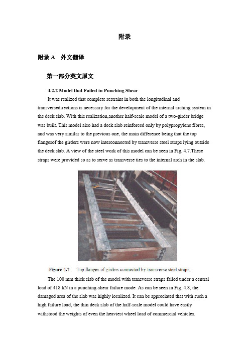
附录附录A 外文翻译第一部分英文原文4.2.2 Model that Failed in Punching ShearIt was realized that complete restraint in both the longitudinal and transversedirections is necessary for the development of the internal arching system in the deck slab. With this realization,another half-scale model of a two-girder bridge was built. This model also had a deck slab reinforced only by polypropylene fibres, and was very similar to the previous one, the main difference being that the top flangesof the girders were now interconnected by transverse steel straps lying outside the deck slab. A view of the steel work of this model can be seen in Fig. 4.7.These straps were provided so as to serve as transverse ties to the internal arch in the slab.The 100 mm thick slab of the model with transverse straps failed under a central load of 418 kN in a punching-shear failure mode. As can be seen in Fig. 4.8, the damaged area of the slab was highly localized. It can be appreciated that with such a high failure load, the thin deck slab of the half-scale model could have easily withstood the weights of even the heaviest wheel load of commercial vehicles.The model tests described above and in sub-section 4.2.1 clearly demonstrate that an internal arching action will indeed develop in a deck slab, but only if it is suitably restrained.4.2.3 Edge StiffeningA further appreciation of the deck slab arching action is provided by tests on a scale model of a skew slab-on-girder bridge. As will be discussed in sub-section 4.4.2, one transverse free edge of the deck slab of this model was stiffened by a composite steel channel with its web in the vertical plane. The other free edge was stiffened by a steel channel diaphragm with its web horizontal and connected to the deck slab through shear connectors. The deck slab near the former transverse edge failed in a mode that was a hybrid between punching shear and flexure. Tests near the composite diaphragm led to failure at a much higher load in punching shear (Bakht and Agarwal, 1993).The above tests confirmed yet again that the presence of the internal arching action in deck slabs induces high in-plane force effects which in turn demand stiffer restraint in the plane of the deck than in the out-of-plane direction.4.3 INTERNALLY RESTRAINED DECK SLABSDeck slabs which require embedded reinforcement for strength will now be referred to as internally restrained deck slabs. The state-of-art up to 1986 relating to the quantification and utilization of the beneficial internal arching action in deck slabs with steel reinforcement has been provided by Bakht and Markovic (1986). Their conclusions complemented with up-to-date information are presented in this chapter in a generally chronological order which, however, cannot be adhered to rigidlybecause of the simultaneous occurrence of some developments.4.3.1 Static Tests on Scale ModelsAbout three decades ago, the Structures Research Office of the Ministry of Transportation of Ontario (MTO), Canada, sponsored an extensive laboratory-based research program into the load carrying capacity of deck slabs; this research program was carried out at Queen's University, Kingston, Ontario. Most of this research was conducted through static tests on scale models of slab-on-girder bridges. This pioneering work is reported by Hewitt and Batchelor (1975) and later by Batchelor et al. (1985), and is summarized in the following.The inability of the concrete to sustain tensile strains, which leads to cracking, has been shown to be the main attribute which causes the compressive membrane forces to develop. This phenomenon is illustrated in Fig. 4.9 (a) which shows the part cross-section of slab-on-girder bridge under the action of a concentrated load.The cracking of the concrete, as shown in the figure, results in a net compressive force near the bottom face of the slab at each of the two girder locations. Midway between the girders, the net compressive force moves towards the top of the slab. It can be readily visualized that the transition of the net compressive force from near the top in the middle region, to near the bottom at the supports corresponds to the familiar arching action. Because of this internal arching action, the failure mode of a deck slab under a concentrated load becomes that of punching shear.If the material of the deck slab has the same stress-strain characteristics in both tension and compression, the slab will not crack and, as shown in Fig. 4.9 (b), will not develop the net compressive force and hence the arching action.In the punching shear type of failure, a frustum separates from the rest of the slab, as shown in schematically in Fig. 4.10. It is noted that in most failure tests, the diameter of the lower end of the frustrum extends to the vicinity of the girders.From analytical and confirmatory laboratory studies, it was established that the most significant factor influencing the failure load of a concrete deck slab is the confinement of the panel under consideration. It was concluded that this confinement is provided by the expanse of the slab beyond the loaded area; its degree was founddifficult to assess analytically. A restraint factor, η, was used as an empirical measure of the confinement; its value is equal to zero for the case of no confinement and 1.0 for full confinement.The effect of various parameters on the failure load can be seen in Table 4.1, which lists the theoretical failure loads for various cases. It can be seen that an increase of the restraint factor from 0.0 to 0.5 results in a very large increase in the failure load. The table also emphasizes the fact that neglect of the restraint factor causes a gross underestimation of the failure load.It was concluded that design for flexure leads to the inclusion of large amounts of unnecessary steel reinforcement in the deck slabs, and that even the minimum amount of steel required for crack control against volumetric changes in concrete is adequate to sustain modern-day, and even future, highway vehicles of North America.It was recommended that for new construction, the reinforcement in a deck slab should be in two layers, with each layer consisting of an orthogonal mesh having the same area of reinforcement in each direction. The area of steel reinforcement in each direction of a mesh was suggested to be 0.2% of the effective area of cross-section of the slab. This empirical method of design was recommended for deck slabs with certain constraints.4.3.2 Pulsating Load Tests on Scale ModelsTo study the fatigue strength of deck slabs with reduced reinforcement, five small scale models with different reinforcement ratios in different panels were tested at the Queen's University at Kingston. Details of this study are reported by Batchelor et al. (1978).Experimental investigation confirmed that for loads normally encountered in North America deck slabs with both conventional and recommended reducedreinforcement have large reserve strengths against failure by fatigue. It was confirmed that the reinforcement in the deck slab should be as noted in sub-section 4.3.1. It is recalled that the 0.2% reinforcement requires that the deck slab must have a minimum restraint factor of 0.5.The work of Okada, et al. (1978) also deals with fatigue tests on full scale models of deck slabs and segments of severely cracked slab removed from eight to ten year old bridges. The application of these test results to deck slabs of actual bridges is open to question because test specimens were removed from the original structures in such a way that they did not retain the confinement necessary for the development of the arching action.4.3.3 Field TestingAlong with the studies described in the preceding sub-section, a program of field testing of the deck slabs of in-service bridges was undertaken by the Structures Research Office of the MTO. The testing consisted of subjecting deck slabs to single concentrated loads, simulating wheel loads, and monitoring the load-deflection characteristics of the slab. The testing is reported by Csagoly et al. (1978) and details of the testing equipment are given by Bakht and Csagoly (1979).Values of the restraint factor, η, were back-calculated from measured deflections.A summary of test results, given in Table 4.2, shows that the average value of η in composite bridges is greater than 0.75, while that for non-composite bridges is 0.42. It was concluded that for new construction, the restraint factor, η, can be assumed to have a minimum value of 0.5.Bakht (1981) reports that after the first application of a test load of high magnitude on deck slabs of existing bridges, a small residual deflection was observed in most cases. Subsequent applications of the same load did not result in further residual deflections. It is postulated that the residual deflections are caused by cracking of the concrete which, as discussed earlier, accompanies the development of the internal arching action. The residual deflections after the first cycle of loading suggest that either the slab was never subjected to loads high enough to cause cracking, or the cracks have 'healed' with time.第二部分汉语翻译4.2.2 在冲切剪应力下的实效模型我们已经知道在桥面板内部拱形系统的形成中,不仅纵向而且横向也被完全约束限制是完全必要的。
预应力混凝土梁桥设计外文文献翻译
预应力混凝土梁桥设计外文文献翻译(文档含中英文对照即英文原文和中文翻译)原文:Analysis of Con tin uous Prestressed Concrete BeamsChris Burgoyne1、IntroductionThis conference is devoted to the development of structural analysis rather than the strength of materials, but the effective use of prestressed concrete relies on an appropriate combination of structural analysis techniques with knowledge of the material behaviour. Design of prestressed concrete structures is usually left to specialists; the unwary will either make mistakes or spend inordinate time trying to extract a solution from the various equations.There are a number of fundamental differences between the behaviour of prestressed concrete and that of other materials. Structures are not unstressed when unloaded; the design space of feasible solutions is totally bounded;in hyperstatic structures, various states of self-stress can be induced by altering the cable profile, and all of these factors get influenced by creep and thermal effects. How were these problemsrecognised and how have they been tackled?Ever since the development of reinforced concrete by Hennebique at the end of the 19th century (Cusack 1984), it was recognised that steel and concrete could be more effectively combined if the steel was pretensioned, putting the concrete into compression. Cracking could be reduced, if not prevented altogether, which would increase stiffness and improve durability. Early attempts all failed because the initial prestress soon vanished, leaving the structure to be- have as though it was reinforced; good descriptions of these attempts are given by Leonhardt (1964) and Abeles (1964).It was Freyssineti’s observations of the sagging o f the shallow arches on three bridges that he had just completed in 1927 over the River Allier near Vichy which led directly to prestressed concrete (Freyssinet 1956). Only the bridge at Boutiron survived WWII (Fig 1). Hitherto, it had been assumed that concrete had a Young’s modulus which remained fixed, but he recognised that the de- ferred strains due to creep explained why the prestress had been lost in the early trials. Freyssinet (Fig. 2) also correctly reasoned that high tensile steel had to be used, so that some prestress would remain after the creep had occurred, and also that high quality concrete should be used, since this minimised the total amount of creep. The history of Freyssineti’s early prestressed concrete work is written elsewhereFigure1:Boutiron Bridge,Vic h yFigure 2: Eugen FreyssinetAt about the same time work was underway on creep at the BRE laboratory in England ((Glanville 1930) and (1933)). It is debatable which man should be given credit for the discovery of creep but Freyssinet clearly gets the credit for successfully using the knowledge to prestress concrete.There are still problems associated with understanding how prestressed concrete works, partly because there is more than one way of thinking about it. These different philosophies are to some extent contradictory, and certainly confusing to the young engineer. It is also reflected, to a certain extent, in the various codes of practice.Permissible stress design philosophy sees prestressed concrete as a way of avoiding cracking by eliminating tensile stresses; the objective is for sufficient compression to remain after creep losses. Untensioned reinforcement, which attracts prestress due to creep, is anathema. This philosophy derives directly from Freyssinet’s logic and is primarily a working stress concept.Ultimate strength philosophy sees prestressing as a way of utilising high tensile steel as reinforcement. High strength steels have high elastic strain capacity, which could not be utilised when used as reinforcement; if the steel is pretensioned, much of that strain capacity is taken out before bonding the steel to the concrete. Structures designed this way are normally designed to be in compression everywhere under permanent loads, but allowed to crack under high live load. The idea derives directly from the work of Dischinger (1936) and his work on the bridge at Aue in 1939 (Schonberg and Fichter 1939), as well as that of Finsterwalder (1939). It is primarily an ultimate load concept. The idea of partial prestressingderives from these ideas.The Load-Balancing philosophy, introduced by T.Y. Lin, uses prestressing to counter the effect of the permanent loads (Lin 1963). The sag of the cables causes an upward force on the beam, which counteracts the load on the beam. Clearly, only one load can be balanced, but if this is taken as the total dead weight, then under that load the beam will perceive only the net axial prestress and will have no tendency to creep up or down.These three philosophies all have their champions, and heated debates take place between them as to which is the most fundamental.2、Section designFrom the outset it was recognised that prestressed concrete has to be checked at both the working load and the ultimate load. For steel structures, and those made from reinforced concrete, there is a fairly direct relationship between the load capacity under an allowable stress design, and that at the ultimate load under an ultimate strength design. Older codes were based on permissible stresses at the working load; new codes use moment capacities at the ultimate load. Different load factors are used in the two codes, but a structure which passes one code is likely to be acceptable under the other.For prestressed concrete, those ideas do not hold, since the structure is highly stressed, even when unloaded. A small increase of load can cause some stress limits to be breached, while a large increase in load might be needed to cross other limits. The designer has considerable freedom to vary both the working load and ultimate load capacities independently; both need to be checked.A designer normally has to check the tensile and compressive stresses, in both the top and bottom fibre of the section, for every load case. The critical sections are normally, but not always, the mid-span and the sections over piers but other sections may become critical ,when the cable profile has to be determined.The stresses at any position are made up of three components, one of which normally has a different sign from the other two; consistency of sign convention is essential.If P is the prestressing force and e its eccentricity, A and Z are the area of the cross-section and its elastic section modulus, while M is the applied moment, then where ft and fc are the permissible stresses in tension and compression.c e t f ZM Z P A P f ≤-+≤Thus, for any combination of P and M , the designer already has four in- equalities to deal with.The prestressing force differs over time, due to creep losses, and a designer is usually faced with at least three combinations of prestressing force and moment;• the applied moment at the time the prestress is first applied, before creep losses occur,• the maximum applied moment after creep losses, and• the minimum applied moment after creep losses.Figure 4: Gustave MagnelOther combinations may be needed in more complex cases. There are at least twelve inequalities that have to be satisfied at any cross-section, but since an I-section can be defined by six variables, and two are needed to define the prestress, the problem is over-specified and it is not immediately obvious which conditions are superfluous. In the hands of inexperienced engineers, the design process can be very long-winded. However, it is possible to separate out the design of the cross-section from the design of the prestress. By considering pairs of stress limits on the same fibre, but for different load cases, the effects of the prestress can be eliminated, leaving expressions of the form:rangestress e Permissibl Range Moment ≤Z These inequalities, which can be evaluated exhaustively with little difficulty, allow the minimum size of the cross-section to be determined.Once a suitable cross-section has been found, the prestress can be designed using a construction due to Magnel (Fig.4). The stress limits can all be rearranged into the form:()M fZ P A Z e ++-≤1By plotting these on a diagram of eccentricity versus the reciprocal of the prestressing force, a series of bound lines will be formed. Provided the inequalities (2) are satisfied, these bound lines will always leave a zone showing all feasible combinations of P and e. The most economical design, using the minimum prestress, usually lies on the right hand side of the diagram, where the design is limited by the permissible tensile stresses.Plotting the eccentricity on the vertical axis allows direct comparison with the crosssection, as shown in Fig. 5. Inequalities (3) make no reference to the physical dimensions of the structure, but these practical cover limits can be shown as wellA good designer knows how changes to the design and the loadings alter the Magnel diagram. Changing both the maximum and minimum bending moments, but keeping the range the same, raises and lowers the feasible region. If the moments become more sagging the feasible region gets lower in the beam.In general, as spans increase, the dead load moments increase in proportion to the live load. A stage will be reached where the economic point (A on Fig.5) moves outside the physical limits of the beam; Guyon (1951a) denoted the limiting condition as the critical span. Shorter spans will be governed by tensile stresses in the two extreme fibres, while longer spanswill be governed by the limiting eccentricity and tensile stresses in the bottom fibre. However, it does not take a large increase in moment ,at which point compressive stresses will govern in the bottom fibre under maximum moment.Only when much longer spans are required, and the feasible region moves as far down as possible, does the structure become governed by compressive stresses in both fibres.3、Continuous beamsThe design of statically determinate beams is relatively straightforward; the engineer can work on the basis of the design of individual cross-sections, as outlined above. A number of complications arise when the structure is indeterminate which means that the designer has to consider, not only a critical section,but also the behaviour of the beam as a whole. These are due to the interaction of a number of factors, such as Creep, Temperature effects and Construction Sequence effects. It is the development of these ideas which forms the core of this paper. The problems of continuity were addressed at a conference in London (Andrew and Witt 1951). The basic principles, and nomenclature, were already in use, but to modern eyes concentration on hand analysis techniques was unusual, and one of the principle concerns seems to have been the difficulty of estimating losses of prestressing force.3.1 Secondary MomentsA prestressing cable in a beam causes the structure to deflect. Unlike the statically determinate beam, where this motion is unrestrained, the movement causes a redistribution of the support reactions which in turn induces additional moments. These are often termed Secondary Moments, but they are not always small, or Parasitic Moments, but they are not always bad.Freyssinet’s bridge across the Marne at Luzancy, started in 1941 but not completed until 1946, is often thought of as a simply supported beam, but it was actually built as a two-hinged arch (Harris 1986), with support reactions adjusted by means of flat jacks and wedges which were later grouted-in (Fig.6). The same principles were applied in the later and larger beams built over the same river.Magnel built the first indeterminate beam bridge at Sclayn, in Belgium (Fig.7) in 1946. The cables are virtually straight, but he adjusted the deck profile so that the cables were close to the soffit near mid-span. Even with straight cables the sagging secondary momentsare large; about 50% of the hogging moment at the central support caused by dead and live load.The secondary moments cannot be found until the profile is known but the cable cannot be designed until the secondary moments are known. Guyon (1951b) introduced the concept of the concordant profile, which is a profile that causes no secondary moments; es and ep thus coincide. Any line of thrust is itself a concordant profile.The designer is then faced with a slightly simpler problem; a cable profile has to be chosen which not only satisfies the eccentricity limits (3) but isalso concordant. That in itself is not a trivial operation, but is helped by the fact that the bending moment diagram that results from any load applied to a beam will itself be a concordant profile for a cable of constant force. Such loads are termed notional loads to distinguish them from the real loads on the structure. Superposition can be used to progressively build up a set of notional loads whose bending moment diagram gives the desired concordant profile.3.2 Temperature effectsTemperature variations apply to all structures but the effect on prestressed concrete beams can be more pronounced than in other structures. The temperature profile through the depth of a beam (Emerson 1973) can be split into three components for the purposes of calculation (Hambly 1991). The first causes a longitudinal expansion, which is normally released by the articulation of the structure; the second causes curvature which leads to deflection in all beams and reactant moments in continuous beams, while the third causes a set of self-equilibrating set of stresses across the cross-section.The reactant moments can be calculated and allowed-for, but it is the self- equilibrating stresses that cause the main problems for prestressed concrete beams. These beams normally have high thermal mass which means that daily temperature variations do not penetrate to the core of the structure. The result is a very non-uniform temperature distribution across the depth which in turn leads to significant self-equilibrating stresses. If the core of the structure is warm, while the surface is cool, such as at night, then quite large tensile stresses can be developed on the top and bottom surfaces. However, they only penetrate a very short distance into the concrete and the potential crack width is very small. It can be very expensive to overcome the tensile stress by changing the section or the prestress。
桥梁工程毕业设计外文翻译(箱梁)

西南交通大学本科毕业设计(论文)外文资料翻译年级:学号:姓名:专业:指导老师:2013年 6 月外文资料原文:13Box girders13.1 GeneralThe box girder is the most flexible bridge deck form。
It can cover a range of spans from25 m up to the largest non—suspended concrete decks built, of the order of 300 m。
Single box girders may also carry decks up to 30 m wide。
For the longer span beams, beyond about 50 m,they are practically the only feasible deck section. For the shorter spans they are in competition with most of the other deck types discussed in this book.The advantages of the box form are principally its high structural efficiency (5.4),which minimises the prestress force required to resist a given bending moment,and its great torsional strength with the capacity this gives to re—centre eccentric live loads,minimising the prestress required to carry them。
The box form lends itself to many of the highly productive methods of bridge construction that have been progressively refined over the last 50 years,such as precast segmental construction with or without epoxy resin in the joints,balanced cantilever erection either cast in—situ or coupled with precast segmental construction, and incremental launching (Chapter 15)。
(完整版)桥梁毕业设计外文翻译
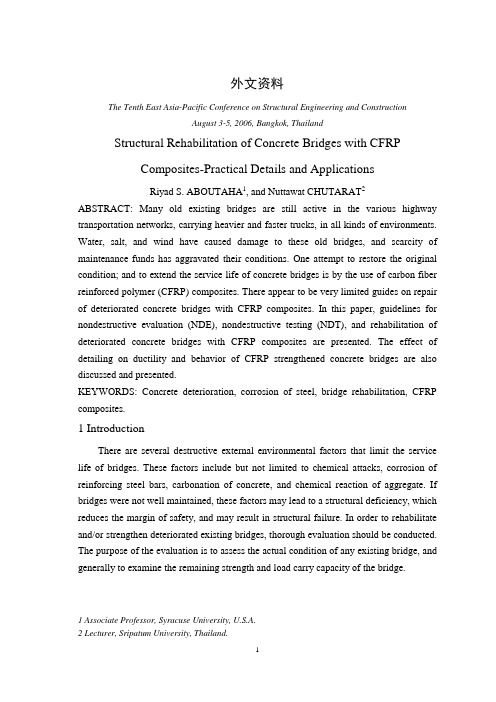
外文资料The Tenth East Asia-Pacific Conference on Structural Engineering and ConstructionAugust 3-5, 2006, Bangkok, ThailandStructural Rehabilitation of Concrete Bridges with CFRPComposites-Practical Details and ApplicationsRiyad S. ABOUTAHA1, and Nuttawat CHUTARAT2 ABSTRACT: Many old existing bridges are still active in the various highway transportation networks, carrying heavier and faster trucks, in all kinds of environments. Water, salt, and wind have caused damage to these old bridges, and scarcity of maintenance funds has aggravated their conditions. One attempt to restore the original condition; and to extend the service life of concrete bridges is by the use of carbon fiber reinforced polymer (CFRP) composites. There appear to be very limited guides on repair of deteriorated concrete bridges with CFRP composites. In this paper, guidelines for nondestructive evaluation (NDE), nondestructive testing (NDT), and rehabilitation of deteriorated concrete bridges with CFRP composites are presented. The effect of detailing on ductility and behavior of CFRP strengthened concrete bridges are also discussed and presented.KEYWORDS: Concrete deterioration, corrosion of steel, bridge rehabilitation, CFRP composites.1 IntroductionThere are several destructive external environmental factors that limit the service life of bridges. These factors include but not limited to chemical attacks, corrosion of reinforcing steel bars, carbonation of concrete, and chemical reaction of aggregate. If bridges were not well maintained, these factors may lead to a structural deficiency, which reduces the margin of safety, and may result in structural failure. In order to rehabilitate and/or strengthen deteriorated existing bridges, thorough evaluation should be conducted. The purpose of the evaluation is to assess the actual condition of any existing bridge, and generally to examine the remaining strength and load carry capacity of the bridge.1 Associate Professor, Syracuse University, U.S.A.2 Lecturer, Sripatum University, Thailand.One attempt to restore the original condition, and to extend the service life of concrete bridges is by the use of carbon fiber reinforced polymer (CFRP) composites.In North America, Europe and Japan, CFRP has been extensively investigated and applied. Several design guides have been developed for strengthening of concrete bridges with CFRP composites. However, there appear to be very limited guides on repair of deteriorated concrete bridges with CFRP composites. This paper presents guidelines for repair of deteriorated concrete bridges, along with proper detailing. Evaluation, nondestructive testing, and rehabilitation of deteriorated concrete bridges with CFRP composites are presented. Successful application of CFRP composites requires good detailing as the forces developed in the CFRP sheets are transferred by bond at the concrete-CFRP interface. The effect of detailing on ductility and behavior of CFRP strengthened concrete bridges will also be discussed and presented.2 Deteriorated Concrete BridgesDurability of bridges is of major concern. Increasing number of bridges are experiencing significant amounts of deterioration prior to reaching their design service life. This premature deterioration considered a problem in terms of the structural integrity and safety of the bridge. In addition, deterioration of a bridge has a considerable magnitude of costs associated with it. In many cases, the root of a deterioration problem is caused by corrosion of steel reinforcement in concrete structures. Concrete normally acts to provide a high degree of protection against corrosion of the embedded reinforcement. However, corrosion will result in those cases that typically experience poor concrete quality, inadequate design or construction, and harsh environmental conditions. If not treated a durability problem, e.g. corrosion, may turn into a strength problem leading to a structural deficiency, as shown in Figure1.Figure1 Corrosion of the steel bars is leading to a structural deficiency3 Non-destructive Testing of Deteriorated Concrete Bridge PiersIn order to design a successful retrofit system, the condition of the existing bridge should be thoroughly evaluated. Evaluation of existing bridge elements or systems involves review of the asbuilt drawings, as well as accurate estimate of the condition of the existing bridge, as shown in Figure2. Depending on the purpose of evaluation, non-destructive tests may involve estimation of strength, salt contents, corrosion rates, alkalinity in concrete, etc.Figure2 Visible concrete distress marked on an elevation of a concrete bridge pier Although most of the non-destructive tests do not cause any damage to existing bridges, some NDT may cause minor local damage (e.g. drilled holes & coring) that should be repaired right after the NDT. These tests are also referred to as partial destructive tests but fall under non-destructive testing.In order to select the most appropriate non-destructive test for a particular case, thepurpose of the test should be identified. In general, there are three types of NDT to investigate: (1) strength, (2) other structural properties, and (3) quality and durability. The strength methods may include; compressive test (e.g. core test/rebound hammer/ ultrasonic pulse velocity), surface hardness test (e.g. rebound hammer), penetration test (e.g. Windsor probe), and pullout test (anchor test).Other structural test methods may include; concrete cover thickness (cover-meter), locating rebars (rebar locator), rebar size (some rebar locators/rebar data scan), concrete moisture (acquameter/moisture meter), cracking (visual test/impact echo/ultrasonic pulse velocity), delamination (hammer test/ ultrasonic pulse velocity/impact echo), flaws and internal cracking (ultrasonic pulse velocity/impact echo), dynamic modulus of elasticity (ultrasonic pulse velocity), Possion’s ratio (ultrasonic pulse velocity), thickness of concrete slab or wall (ultrasonic pulse velocity), CFRP debonding (hammer test/infrared thermographic technique), and stain on concrete surface (visual inspection).Quality and durability test methods may include; rebar corrosion rate –field test, chloride profile field test, rebar corrosion analysis, rebar resistivity test, alkali-silica reactivity field test, concrete alkalinity test (carbonation field test), concrete permeability (field test for permeability).4 Non-destructive Evaluation of Deteriorated Concrete Bridge PiersThe process of evaluating the structural condition of an existing concrete bridge consists of collecting information, e.g. drawings and construction & inspection records, analyzing NDT data, and structural analysis of the bridge. The evaluation process can be summarized as follows: (1) Planning for the assessment, (2) Preliminary assessment, which involves examination of available documents, site inspection, materials assessment, and preliminary analysis, (3) Preliminary evaluation, this involves: examination phase, and judgmental phase, and finally (4) the cost-impact study.If the information is insufficient to conduct evaluation to a specific required level, then a detailed evaluation may be conducted following similar steps for the above-mentioned preliminary assessment, but in-depth assessment. Successful analytical evaluation of an existing deteriorated concrete bridge should consider the actual condition of the bridge and level of deterioration of various elements. Factors, e.g. actual concrete strength, level of damage/deterioration, actual size of corroded rebars, loss of bond between steel and concrete, etc. should be modeled into a detailed analysis. If such detailed analysis is difficult to accomplish within a reasonable period of time, thenevaluation by field load testing of the actual bridge in question may be required.5 Bridge Rehabilitation with CFRP CompositesApplication of CFRP composite materials is becoming increasingly attractive to extend the service life of existing concrete bridges. The technology of strengthening existing bridges with externally bonded CFRP composites was developed primarily in Japan (FRP sheets), and Europe (laminates). The use of these materials for strengthening existing concrete bridges started in the 1980s, first as a substitute to bonded steel plates, and then as a substitute for steel jackets for seismic retrofit of bridge columns. CFRP Composite materials are composed of fiber reinforcement bonded together with a resin matrix. The fibers provide the composite with its unique structural properties. The resin matrix supports the fibers, protect them, and transfer the applied load to the fibers through shearing stresses. Most of the commercially available CFRP systems in the construction market consist of uniaxial fibers embedded in a resin matrix, typically epoxy. Carbon fibers have limited ultimate strain, which may limit the deformability of strengthened members. However, under traffic loads, local debonding between FRP sheets and concrete substrate would allow for acceptable level of global deformations before failure.CFRP composites could be used to increase the flexural and shear strength of bridge girders including pier cap beams, as shown in Figure3. In order to increase the ductility of CFRP strengthened concrete girders, the longitudinal CFRP composite sheets used for flexural strengthening should be anchored with transverse/diagonal CFRP anchors to prevent premature delamination of the longitudinal sheets due to localized debonding at the concrete surface-CFRP sheet interface. In order to prevent stress concentration and premature fracture of the CFRP sheets at the corners of concrete members, the corners should be rounded at 50mm (2.0 inch) radius, as shown in Figure3.Deterioration of concrete bridge members due to corrosion of steel bars usually leads in loss of steel section and delamination of concrete cover. As a result, such deterioration may lead to structural deficiency that requires immediate attention. Figure4 shows rehabilitation of structurally deficient concrete bridge pier using CFRP composites.Figure3 Flexural and shear strengthening of concrete bridge pier with FRP compositesFigure4 Rehabilitation of deteriorated concrete bridge pier with CFRP composites6 Summary and ConclusionsEvaluation, non-destructive testing and rehabilitation of deteriorated concrete bridges were presented. Deterioration of concrete bridge components due to corrosion may lead to structural deficiencies, e.g. flexural and/or shear failures. Application of CFRP composite materials is becoming increasingly attractive solution to extend the service life of existing concrete bridges. CFRP composites could be utilized for flexural and shear strengthening, as well as for restoration of deteriorated concrete bridge components. The CFRP composite sheets should be well detailed to prevent stress concentration and premature fracture or delamination. For successful rehabilitation of concrete bridges in corrosive environments, a corrosion protection system should be used along with the CFRP system.第十届东亚太结构工程设计与施工会议2006年8月3-5号,曼谷,泰国碳纤维复合材料修复混凝土桥梁结构的详述及应用Riyad S. ABOUTAHA1, and Nuttawat CHUTARAT2摘要:在各式各样的公路交通网络中,许多现有的古老桥梁,在各种恶劣的环境下,如更重的荷载和更快的车辆等条件下,依然在被使用着。
土木工程桥梁方向毕业设计外文及翻译

土木工程桥梁方向毕业设计外文及翻译(总13页)--本页仅作为文档封面,使用时请直接删除即可----内页可以根据需求调整合适字体及大小--学生姓名:学号:班级:专业:土木工程(桥梁方向)指导教师:2010 年 3 月What is traffic engineeringTraffic engineering is still a relatively new discipline within the overall bounds of civil engineering. it has nevertheless already been partially planning. the disciplines are not synonymous though. transportation planning is concerned with the planning, functional design, operation and management of facilities for any mode of transportation in order to provide for the safe, rapid, comfortable, convenient, economical and enviromenally-comparible movement of people and goods. within that broad scope, traffic engineering deals with those functions in respect of roads, road networks, terminal points , about lands and their relationships with other modes of transportation.Those definitions, based on the 1976 ones of the of transportation engineers are complete than, the British instituting of civil engineering which deals with traffic planning and design of roads, of frontage development and of parking facilities and with the control of traffic to provide safe, convenient and economical movement of vehicles and pedestrians.The definitions of the disicipline are becoming clearer: the methodology is developing continuously and becoming increasingly scientific. the early rule-of-thumb techniques are disappearing.Traffic problemThe discipline is young: the problem is large and still growing. in 1920 the total number of motor vehicles, licensed in great Britain was,650, year later the comparable figure was 14,950,000-a growth factor of 23 times. in recent years the rate of growth has slackened somewhat, but it is still considerable: 1955 6,466,0001960 9,439,0001965 12,938,0001970 14,950,0001974 17,247,000In order to see the problem in every day terms ,consider high street. anywhere. assuming that present trends continue, it is expected that within the next fifteen years of so the traffic on this road will increase by around forty to fifty persent. if this increased volume of traffic were to be accommodated at the same standard as today, the road might need to be widened by a similar forty to fifty percent-perhaps extra lane of traffic for the pedestrian to cross. In man cases, to accommodate the foreseeable future demand would destroy the character of the whole urban environment, and is clearly unacceptable.the traffic problem is of world-wide concern, but different countries are obviously at different stages in the traffic escalation-with America in the lead, while a county has few roads and a relatively low problem, as soon as the country is opened up by a road system, the standard of living and the demand for motor transport both rise, gathering momentum rapidly. eventually-and the stage at which this happens is open to considerable debate-the demand for cars, buses and lorries become satiated. the stage is known as saturation level.For comparison ,car ownership figures in different countries in 1970 were:India cars/personIsrael personJapan cars/personIreland cars/personNetherlands cars/personGreat Britain cars/personWest Germany cars/personAustralia cars/personUSA cars/personBut the growth in vehicle ownership is only part of the overall traffic problem. obviously,if a country has unlimited roads of extreme width, the traffic problem would not rise. no country in the world could meet this requirement: apart from anything else, it would not make economic for each vehicle using the roads. This figure is decreasing steadily.Three possible solutionsThe basic problem of traffic is therefore simple-an ever-increasing number of vehicles seeking to use too little roade space. the solution to the problem-is else a not-too-difficult choice from three possiblilities:build, sufficient roads of sufficient size to cope with the demand.Restrict the demand for roads by restricting the numbers of licensed vehicles.A compromise between (a) and (b) build some extra roads, using the and the existing road network to their full potential, and at the same time apply some restraint measures, limiting, the increase in demand as far as possible.With no visible end to the demand yet in sight, and 216 with modern road-making costs ranging around £1 million per kilometer cost of building roads in Britain to cope with an unrestricted demand would be far too great. added to this, such clossal use of space in a crowed island cannot be, seriously considered. in Los Angeles, a city built around the parking space for, the automobile. our citie are already largely built-and no one would consider ruining their character by pulling them down and rebuilding around the car, thus the first possible soluting is rule out.Even today,in an age of at least semi-affluence in most of the Western World, the car is still to some extent a status symbol, a symbol of family wants to own one, and takes steps saving or borrowing-to get one. as incomes and standards rise thesecond car becomes the target. any move to restrict the acquisition of the private car would be most unpopular-and politically unlikely.For many purpose the flexibility of the private car-conceptually affording door-to-door personal transport is ideal, and its use can be accommodate. for the mass, movement of people along specific corridors within a limited period of .. particularly the journey to work it may be less easily accommodated. other transport mode may be more efficient. some sort of compromise solution is the inevitable answer to the basic traffic problem .it is in the execution of the compromise solution that, traffic engineering comes into its own. traffic engineering ensures that any new facilities are not over-deigned and are correctly located to meet the demand. it ensures that the existing facilities are fully used, in the most efficient manner. the fulfillment of these duties may entail the selective throttling of demand: making the use of the car less attractive in the peak periods in order that the limited road space can be more efficiently used by public transport.Such restraint measures will often be accompanied by improvements in the public transport services, to accommodate the extra demand for them.Prestressed Concrete BridgesPrestressed concrete has been used extensively in . bridge construction since its first Introduction from Europe in the late 1940s. Literally thousands of highway bridges of both precast, prestressed concrete and cast-in-place post-tensioned concrete has been constructed in the United States. Railroad bridges utilizing prastressed concrete have become common as well. The use and evolution of prastressed concrete bridges is expected to continue in the years ahead.Short-span BridgesShort-span bridges will be assumed to have a maximum of 45 ft .It should be understood that this is an arbitrary figure, and there is no definite line of demarcation between short, moderate, and long spans in highway bridges. Short-span bridges are most efficiently made of precast ,prestressed-concrete hollow slabs, I-beams, solid slabs or cast-place solid slabs. and T-beams of relatively generous proportions.Precast solid slabs are most economical when used on very short spans. The slabs can be made in any convenient width,but widths of 3 or 4 ft to have been frequently are cast in the longitudinal sides of the precast units. After the slabs have been erected and the joints between the slabs have been filled with concrete, the keys transfer live load shear forces between the adjacent slabs.Precast hollow slabs used in short-span bridges may have round or square voids. They too are generally made in units 3 to 4 ft to m) wide with thicknesses from 18 to 27 in to . Precast hollow slabs can be made in any convenient width and depth, and frequently are used in bridges having spans from 20 to 50 ft to . Longitudinal shear keys are used in the joints between adjacent hollow slabs in the same way as with solid slabs. Hollow slabs may or may not be used with a composite, cast-in-place concrete topping an accecptable appearance and levelness.Transverse reinforcement normally is provided in precast concrete bridge superstructures for the purpose of tying the structure together in the transverse direction. Well-designed ties ensure that the individual longitudinal members forming the superstructure will act as a unit under the effects of the live load. In slab bridge construction, transverse ties most frequently consist of threaded steel bars placed through small holes formed transversely through the member during fabrication. Nuts frequently are used as fasteners at each end of the bars. In some instances, the transverse ties consist of post tensionedtendons placed, stressed, and grouted after the slabs have been erected. The transverse tie usually extends from one side of the bridge to the other.The shear forces imposed on the stringers in short-span bridges frequently are too large to be resisted by the concrete alone. Hence, shear reinforcement normally is required. The amount of shear reinforcement required may be relatively large if the webs of the stringers are relatively thin.Concrete diaphragms, reinforced with post-tensioned reinforcement or nonprestressed reinforcement, normally are provided transversely at the ends and at intermediate locations along the span in stringer-type bridges. The disaphragms ensure the lateral-distribution of the live load to the various stringers and prevent individual stringers from displacing or rotating significantly with respect to the adjacent stringers.No generalities will be made here about the relative cost of each of the above types of construction; construction costs are a function of many variables which prohibit meaningful generalizations. However, it should be noted that the stringer type of construction requires a considerably greater construction depth that is required for solid, hollow, or channel slab bridge superstructures. Stringer construction does not require a separate wearing surface, as do the precast slab types of construction, unless precast slabs are used to span between the stringers in lieu of the more commonly used cast-in-place reinforced concrete deck. Stringer construction frequently requires smaller quantities of superstructure materials than do slab bridges (unless the spans are very short). The construction time needed to complete a bridge after the precast members have been erected is greater with stringer framing than with the slab type of framing.Bridges Of Moderate SpanAgain for the purpose of this discussion only, moderate spans for bridges of prestressed concrete are defined as beingfrom 45 to 80 ft to . Prestressed concrete bridges in this span range generally can be divided into two types: stringer-type bridges and slab-type bridges. The majority of the precast prestressed concrete bridges constructed in the United States have been stringer bridges using I-shaped stringers, but a large number of precast prestressed concrete bridges have been constructed with precast hollow-box girders (sometimes also called stringers). Cast-in-place post-tensioned concrete has been used extensively in the construction of hollow-box girder bridges-a form of construction that can be considered to be a slab bridge.Stringer bridges, which employ a composite, cast-in-place deck slab, have been used in virtually all parts of the United States. These stringers normally are used at spacing s of about 5 to 6 ft to . The cast-in-place deck is generally from to in to in thickness. This type of framing is very much the same as that used on composite-stringer construction for short-span bridges.Diaphram details in moderate-span bridges are generally similar to those of the short spans, with the exception that two or three interior diaphragms sometime are used, rather than just one at midspan as in the short-span bridge.As in the case of short-span bridges, the minimum depth of construction in bridges of moderate span is obtained by using slab construction, which may be either solid – or hollow – box in cross section. Average construction depths are requires when stringers with large flanges are used in composite construction, and large construction depths are required when stringers with small bottom flanges are used. Composite construction may be developed through the use of cast-in-place concrete decks or with precast concrete decks. Lower quantities of materials normally are required with composite construction , and the dead weight of the superstructure normally is less for stringer construction than for slab construction.Long-Span BridgesPrestressed concrete bridges having spans of the order of 100ft are of the same general types of construction as structures having moderate span lengths, with the single exception that solid slabs are not used for long spans. The stringer spacings are frequently greater (with stringers at 7 to 9 ft) as the span lengths of bridges increase. Because of dead weight considerations, precast hollow-box construction generally is employed for spans of this length only when the depth of construction must be minimized. Cast-in-place post-tensioned hollow-box bridges with simple and continuous spans frequently are used for spans on the order of 100 ft and longer.Simple, precast, prestressed stringer construction would be economical in the United States in the spans up to 300 ft under some conditions. However, only limited use has been made of this type of construction on spans greater than 100 ft. For very long simple spans, the advantage of precasting frequently is nullified by the difficulties involved in handling, transporting, and erecing the girders, which may have depths as great as 10 ft and weigh over 200 tons. The exceptions to this occur on large projects where all of the spans are over water of sufficient depth and character that precast beams can be handled with floating equipment, when custom girder launchers can be used, and when segmental construction techniques can be used.The use of cast-in-place , post-tensioned, box-girder bridges has been extensive. Although structures of these types occasionally are used for spans less than 100ft, they more often are used for spans in excess of 100 ft and have been used in structuresHaving spans in excess of 300 ft. Structurally efficient in flexure, especially for continuous bridges, the box girder is torsionally stiff and hence an excellent type of structure for use on bridges that have horizontal curvature. Some governmental agencies use this form of construction almost exclusively in urban areas where appearance from underneath the superstructure,as well as from the side, is considered important.交通工程介绍什么是交通工程交通工程仍然是在土木工程的总的界限内的一种相对新的训练。
桥梁设计外文翻译

中文4840字附录 2 外文资料翻译原文11.7.4 Deflection11.7.4.1 Dead Load and Creep DeflectionGlobal vertical deflections of segmental box-girder bridges due to the effects of dead load and post-tensioning as well as the long-term effect of creep are normally predicted during the design process by the use of a computer analysis program. The deflections are dependent, to a large extent, on the method of construction of the structure, the age of the segments when post-tensioned, and the age of the structure when other loads are applied. It can be expected, therefore, that the actual deflections of the structure would be different from that predicted during design due to changed assumptions.The deflections are usually recalculated by the contractor’s engineer, based on the actual construction sequence.11.7.4.2 Camber RequirementsThe permanent deflection of the structure after all creep deflections have occurred, normally 10 to 15 years after construction, may be objectionable from the perspective of riding comf ort for the users or for the confidence of the general public. Even if there is no structural problem with a span with noticeable sag, it will not inspire public confidence. For these reasons, a camber will normally be cast into the structure so that the p ermanent deflection of the bridge is nearly zero. It may be preferable to ignore the camber, if it is otherwise necessary to cast a sag in the structure during onstruction.11.7.4.3 Global Deflection Due to Live LoadMost design codes have a lim it on the allowable global deflection of a bridge span due to the effects of live load. The purpose of this limit is to avoid the noticeable vibration for the user and minimize the effects of moving load iMPact. When structures are used by pedestrians as well as motorists,the limits are further tightened.11.7.4.4 Local Deflection Due to Live LoadSimilar to the limits of global deflection of bridge spans, there are also limitations on the deflection of the local elements of the box-girder cross section. For example, the AASHTO Specifications limit the deflection of cantilever arms due to service live load plus iMPact to ¹⁄₃of the cantilever length,except where there is pedestrian use [1].11.7.5 Post-Tensioning Layout11.7.5.1 Exter nal Post-TensioningWhile most concrete bridges cast on falsework or precast beam bridges have utilized post-tensioning in ducts which are fully encased in the concrete section, other innovations have been made in precast segmental construction.Especially prevalent in structures constructed using the span-by-span method, post-tensioning has been placed inside the hollow cell of the box girder but not encased in concrete along its length. This is know as external post-tensioning. External post-tensioning is easily inspected at any time during the life of the structure, eliminates the problems associated with internal tendons, and eliminates the need for using expensive epoxy adhesive between precastsegments. The problems associated with internal tendons are (1) misalignment of the tendons at segment joints, which causes spalling; (2) lack of sheathing at segment joints; and (3) tendon pull-through on spans with tight curvature (see Figure 11.39). External prestressing has been used on many projects in Europe, the United States, and Asia and has performed well.11.7.5The provision for the addition of post-tensioning in the future in order to correct unacceptable creep deflections or to strengthen the structure for additional dead load, i.e., future wearing surface, is now required by many codes. Of the positive and negative moment post-tensioning, 10% is reasonable. Provisions should be made for access, anchorage attachment, and deviation of these additional tendons. External, unbonded tendons are used so that ungrouted ducts in the concrete are not left open. 11.8 Seismic Considerations11.8.1 Design Aspects and Design CodesDue to typical vibration characteristics of bridges, it is generally accepted that under seismic loads,some portion of the structure will be allowed to yield, to dissipate energy, and to increase the period of vibration of the system. This yielding is usually achieved by either allowing the columns to yield plastically (monolithic deck/superstructure connection), or by providing a yielding or a soft bearing system [6].The same principles also apply to segmental structures, i.e., the segmental superstructureneeds to resist the demands imposed by the substructure. Very few implementations of segmental struc-tures are found in seismically active California, where most of the research on earthquake-resistant bridges is conducted in the United States. The Pine Valley Creek Bridge, Parrots Ferry Bridge, and Norwalk/El Segundo Line Overcrossing, all of them being in California, are examples of segmental structures; however, these bridges are all segmentally cast in place, with mild reinforcement crossing the segment joints.Some guidance for the seismic design of segmental structures is provided in the latest edition of the AASHTO Guide Specifications for Design and Construction of Segmental Concrete Bridges [2], which now contains a chapter dedicated to seismic design. The guide allows precast-segmental construction without reinforcement across the joint, but specifies the following additional require-ments for these structures:•For Seismic Zones C and D [1], either cast-in-place or epoxied joints are required.•At least 50% of the prestress force should be provided by internal tendons.•The internal tendons alone should be able to carry 130% of the dead load.For other seismic design and detailing issues, the reader is referred to the design literature providedby the California Department of Transportation, Caltrans, for cast-in-place structures [5-8].11.8.2 Deck/Superstructure ConnectionRegardless of the design approach adopted (ductility through plastic hinging of the column or through bearings), the deck/superstructure connection is a critical element in the seismic resistant system. A brief description of the different possibilities follows.11.8.2.1 Monolithic Deck/Superstructure ConnectionFor the longitudinal direction, plastic hinging will form at the top and bottom of the columns. Since most of the testing has been conducted on cast-in-place joints, this continues to be the preferred option for these cases. For short columns and for solid columns, the detailing in this area can be readily adapted from standard Caltrans practice for cast-in-place structures, as shown on Figure 11.40. The joint area is then essentially detailed so it is no different from that of a fully cast-in-place bridge. In particular, a Caltrans requirement for positive moment reinforcement over the pier can be detailed with prestressing strand, as shown below. For large spans and tall columns, hollow column sections would be more appropriate. In these cases, care should be taken to confine the main column bars with closely spaced ties, and joint shear reinforcement should be provided according to Reference [3 or 7]. The use of fully precast pier segments in segmental superstructures would probably require special approval of the regulating government agency, since such a solution has not yet been tested for bridges and is not codified. Nevertheless, based upon first principles, and with the help of strut–tiemodels, it is possible to design systems that would work in practice [6]. The segmental superstructure should be designed to resist at least 130%of the column nominal moment using the strength reduction factors prescribed in Ref. [2]. Of further interest may be a combination of precast and cast-in-place joint as shown in Figure 11.41, which was adapted from Ref.[8]. Here, the precast segment serves as a form for the cast-in-place portion that fills up the remainder of the solid pier cap. Other ideas can also be derived from the building industry where some model testing has been performed. Of particular interest for bridges could be a system that works by leaving dowels in the columns and supplying the precast segment with matching formed holes, which are grouted after the segment is slipped over the reinforcement [9]11.8.2.2Deck/Superstructure Connection via BearingsTypically, for spans up to 45 m erected with the span-by-span method, the superstructure will be supported on bearings. For action in the longitudinal direction, elastomeric or isolation bearings are preferred to a fixed-end/expansion-end arrangement, since these better distribute the load between the bearings. Furthermore, these bearings will increase the period of the structure, which results in an overall lower induced force level (beneficial for higher-frequency structures), and isolation bearings will provide some structural damping as well.In the transverse direction, the bearings may be able to transfer load between super- and sub-structure by shear deformation; however, for the cases where this is not possible, shear keys can be provided as is shown in Figure 11.42. It should be noted that in regions of high seismicity,for structures with tall piers or soft substructures, the bearing demands may become excessive and a monolithic deck–superstructure connection may become necessary.For the structure-on-bearings approach, the force level for the superstructure can be readily,determined, since once the bearing demands are obtained from the analysis, they can be applied to the superstructure and substructure. The superstructure should resist the resulting forces at ultimate (using the applicable code force-reduction factors), whereas the substructure can be allowed to yield plastically if necessary.11.8.2.3 Expansion HingesFrom the seismic point of view, it is desirable to reduce the number of expansion hinges (EH)to a minimum. If EHs are needed, the most beneficial location from the seismic point of view is at midspan. This can be explained by observing Figure 11.43, where the superstructure bending midspan and for an EH at quarterspan. For the latter, it can be seen that the moment at the face The location of expansion hinges within a span, and its characteristics, depends also on the stiffness of the substructure and the type of connection of the superstructure to the piers. presents general guidelines intended to assist in the selection of location of expansion hinges.11.8.2.4 Precast Segmental PiersPrecast segmental piers are usually hollow cross section to save weight. From research inother areas it can be extrapolated that the precast segments of the pier would be joined by means of unbonded prestressing tendons anchored in the footing. The advantage of unbonded over bonded tendons is that for the former, the prestress force would not increase signi ficantly under high column displace-ment demands, and would therefore not cause inelastic yielding of the strand, which would other-wise lead to a loss of prestress.The detail of the connection to the superstructure and foundation would require some insight into the dynamic characteristics of such a connection, which entails joint opening and closing providing that dry joints are used between segments. This effect is similar to footing rocking, which is well known to be bene ficial to the response of a structure in an earthquake. This is due to the period shift and the damping of the soil. The latter effect is clearly not available to the precast columns, but the period shift is. Details need to be developed for the bearing areas at the end of the columns, as well as the provision for clearance of the tendons to move relative to the pier during the event.If the upper column segment is designed to be connected monolithically to the superstructure, yielding of the reinforcement should be expected. In this case, the expected plastic hinge length should be detailed ductile, using closely spaced ties [3,5].11.9 Casting and Erection11.9.1 CastingThere are obvious major differences in casting and erection when working with cast-in-placecantilever in travelers or in handling precast segments. There are also common features, which must be kept in mind in the design stages to keep the projects simple and thereby economic and ef ficient,such as• Keeping the length of segments equal and segments straight, even in curved bridges; • Maintaining constant cross section dimensions as much as possible;• Minimizing the number of diaphragms and stiffeners, and avoiding dowels through form- work.11.9.1.1 Cast-in-Place CantileversThe conventional form traveler supports the weight of the fresh concrete of the new segment by means of longitudinal beams or frames extending out in cantilever from the last segment. These beams are tied down to the previous segment. A counterweight is used when launching the traveler forward. The main beams are subjected to some de flections, which may produce cracks in the joint between the old and new segments. Jacking of the form during casting is sometimes needed to avoid these cracks. The weight of a traveler is about 60% of the weight of the segment.The rate of construction is typically one segment per traveler per week. Precast concrete anchor blocks are used to speed up post-tensioning operations. In cold climates, Conventional Travelers Construction Camber Controlcuring can be accelerated by various heating processes.The most critical practical problem of cast-in-place construction is deflection control. There are five categories of deflections during and after construction:•Deflection of traveler frame under the weight of the concrete segment;•Deflection of the concrete cantilever arm during construction under the weight of segment plus post-tensioning;•Deflection of cantilever arms after construction and before continuity;•Short- and long-term deflections of the continuous structure;•Short- and long-term pier shortenings and foundation settlements.The sum of the various deflection values for the successive sections of the deck allows the construc-tion of a camber diagram to be added to the theoretical profile of the bridge. A construction camber for setting the elevation of the traveler at each joint must also be developed.11.9.1.2 Precast SegmentsOpposite to the precast girder concept where the bridge is cut longitudinally in the precast segmental methods, the bridge is cut transversally, each slice being a segment. Segments are cast in a casting yard one at a time. Furthermore, the new segment is cast against the previously cast segment so that the faces in contact match perfectly. This is the match-cast principle. When the segments are reassembled at the bridge site, they will take the same relative position with regard to the adjacent segments that they had when they were cast. Accuracy of segment geometry is an absolute priority, and adequate surveying methods must be used to ensure follow-up of the geometry.Match casting of the segments is a prerequisite for the application of glued joints, achieved by covering the end face of one or both of the meeting segments with epoxy at the erection. The epoxy serves as a lubricant during the assembly of the segments, and it ensures a watertight joint in thefinished structure. Full watertightness is needed for corrosion protection of internal tendons (ten-dons inside the concrete). The tensile strength of the epoxy material is higher than that of the concrete, but, even so, the strength of the epoxy is not considered in the structural behavior of the joint. The required shear capacity is generally provided by shear keys, single or multiple, in com-bination with longitudinal post-tensioning.With the introduction of external post-tensioning, where the tendons are installed in PE ducts,outside the concrete but inside the box girder, the joints are relieved of the traditional requirement of watertightness and are left dry. The introduction of external tendons in connection with dry joints greatly enhanced the efficiency of precasting.11.9.1.3 Casting MethodsThere are two methods for casting segments. The first one is the long-line method, where all the segments are cast in their correct position on a casting bed that reproduces the span. The second method, used most of the time, is the short-line method, where all segments are cast in the same place in a stationary form, and against the previously cast segment. After casting and initial curing, the previously cast segment isremoved for storage, and the freshly cast segment is moved into place.11.9.1.4 Geometry ControlA pure translation of each segment between cast and match-cast position results in a straight bridge(Figure 11.45). To obtain a bridge with a vertical curve, the match-cast segment must first be translated and given a rotation in the vertical plane (Figure 11.46). Practically, the bulkhead is left fixed and the mold bottom under the conjugate unit adjusted. To obtain a horizontal curvature, the conjugate unit is given a rotation in the horizontal plane (see Figure 11.47). To obtain a variable superelevation, the conjugate unit is rotated around a horizontal axis located in the middle of the top slab (Figure 11.48).All these adjustments of the conjugate unit can be combined to obtain the desired geometry of the bridge.11.9.2 ErectionThe type of erection equipment depends upon the erection scheme contemplated during the design process; the local conditions, either over water or land; the speed of erection and overall construction schedule. It falls into three categories, independent lifting equipment such as cranes,deck-mounted lifting equipment such as beam and winch or swivel crane, and launching girder equipment.The principle of the method is to erect or cast the pier segment first, then to place typical segments one by one from each side of the pier, or in pairs simultaneously from both sides. Each newly placed precast segment is fixed to the previous one with temporary PT bars, until the cantilever tendons are installed and stressed. The closure joint between cantilever tips is poured in place and continuity tendons installed and stressed.In order to carry out this erection scheme, segments must be lifted and installed at the proper location. The simplest way is to use a crane, either on land or barge mounted. Many bridges have Bridge with superelevation.been erected with cranes as they do not require an investment in special lifting equipment. This method is slow. Typically, two to four segments per day are placed. It is used on relatively short bridges. An alternative is to have a winch on the last segment erected. The winch is mounted on a beam fixed to the segment. It picks up segments from below, directly from truck or barge. After placing the segment, the beam and winch system is moved forward to pick up the next segment and so on. Usually, a beam-and-winch system is placed on each cantilever tip. This method is also slow; however, it does not require a heavy crane on the site, which is always very expensive, especially if the segments are heavy.When bridges are long and the erection schedule short, the best method is the use of launching girders, which then take full advantage of the precast segmental concept for speed of erection.There are two essential types of self-launching gantries developed for this erection method. The first type is a gantry with a length slightly longer than the typical span (see Figure 11.49). During erection of the cantilever, the center leg rests on the pier while the rear leg rests on the cantilever tip of the previously erected span, which must resist the corresponding reaction. Prior to launching,the back spans must be made continuous. Then, the center leg is moved to the forward cantilever tip, which must resist the weight of the gantry plus the weight of the pier segment.This stage controls the design of the gantry, which must be made as light as possible, and of the cantilever.The second type of gantry has a length that is twice that of the typical span (see Figure 11.50).The reaction from the legs during the erection and launching of the next span is always applied on the piers, so there is no concentrated erection load on the cantilever tip. Each erection cycle consists of the erection of all typical segments of the cantilever and then the placement of the pier segment for the next cantilever, without changing the position of the truss.The gantries can be categorized by their cross section: single truss, with portal-type legs, and two launching trusses with a gantry across. The twin box girders of the bridge in Hawaii were built with two parallel, but independent trusses (see Figure 11.51), with a typical span of 100.0 m, segmentweights of 70 tons; the two bridge structures are 27.5 m apart with different elevations and longi-tudinal slopes. This system is a refinement of the first type of gantry applied to twin decks with variable geometry.Normally, the balanced cantilever method is used for spans from 60 to 110 m, with a launching girder. One full, typical cycle of erection is placing segments, installing and stressing post-tensioning tendons, and launching the truss to its next position. It takes about 7 to 10 days, but may vary greatly according to the specifics of a project and the sophistication of the launching girder. With proper equipment and planning, erection of 16 segments per day has been achieved.译文11.7.4 挠度11.7.4.1 恒载和徐变部分箱梁的整体变形是由恒载和后加张力造成的,也包括在设计过程中用电脑分析软件正常算出的徐变的长期影响。
桥梁英语词汇

下部结构 substructure桥墩 pier 墩身 pier body墩帽 pier cap, pier coping台帽 abutment cap, abutment coping盖梁 bent cap又称“帽梁”。
重力式[桥]墩 gravity pier实体[桥]墩 solid pier空心[桥]墩 hollow pier柱式[桥]墩 column pier, shaft pier单柱式[桥]墩 single-columned pier, single shaft pier 双柱式[桥]墩 two-columned pier, two shaft pier排架桩墩 pile-bent pier丫形[桥]墩 Y-shaped pier柔性墩 flexible pier制动墩 braking pier, abutment pier单向推力墩 single direction thrusted pier抗撞墩 anti-collision pier锚墩 anchor pier辅助墩 auxiliary pier破冰体 ice apron防震挡块 anti-knock block, restrain block桥台 abutment台身 abutment body前墙 front wall又称“胸墙”。
翼墙 wing wall又称“耳墙”。
U形桥台 U-abutment八字形桥台 flare wing-walled abutment一字形桥台 head wall abutmentT形桥台 T-abutment箱形桥台 box type abutment拱形桥台 arched abutment重力式桥台 gravity abutment埋置式桥台 buried abutment扶壁式桥台 counterfort abutment, buttressed abutment 衡重式桥台 weight-balanced abutment锚碇板式桥台 anchored bulkhead abutment支撑式桥台 supported type abutment又称“轻型桥台”。
桥梁毕业设计外文原文及翻译

外文文献翻译BRIDGE ENGINEERING AND AESTHETICSEvolvement of bridge Engineering,brief reviewAmong the early documented reviews of construction materials and structure types are the books of Marcus Vitruvios Pollio in the first century B.C.The basic principles of statics were developed by the Greeks , and were exemplified in works and applications by Leonardo da Vinci,Cardeno,and Galileo.In the fifteenth and sixteenth century, engineers seemed to be unaware of this record , and relied solely on experience and tradition for building bridges and aqueducts .The state of the art changed rapidly toward the end of the seventeenth century when Leibnitz, Newton, and Bernoulli introduced mathematical formulations. Published works by Lahire (1695)and Belidor (1792) about the theoretical analysis of structures provided the basis in the field of mechanics of materials .Kuzmanovic(1977) focuses on stone and wood as the first bridge-building materials. Iron was introduced during the transitional period from wood to steel .According to recent records , concrete was used in France as early as 1840 for a bridge 39 feet (12 m) long to span the Garoyne Canal at Grisoles, but reinforced concrete was not introduced in bridge construction until the beginning of this century . Prestressed concrete was first used in 1927.Stone bridges of the arch type (integrated superstructure and substructure) were constructed in Rome and other European cities in the middle ages . These arches were half-circular , with flat arches beginning to dominate bridge work during the Renaissance period. This concept was markedly improved at the end of the eighteenth century and found structurally adequate to accommodate future railroad loads . In terms of analysis and use of materials , stone bridges have not changed much ,but the theoretical treatment was improved by introducing the pressure-line concept in the early 1670s(Lahire, 1695) . The arch theory was documented in model tests where typical failure modes were considered (Frezier,1739).Culmann(1851) introduced the elastic center method for fixed-end arches, and showed that three redundant parameters can be found by the use of three equations of coMPatibility.Wooden trusses were used in bridges during the sixteenth century when Palladio built triangular frames for bridge spans 10 feet long . This effort also focused on the three basic principles og bridge design : convenience(serviceability) ,appearance , and endurance(strength) . several timber truss bridges were constructed in western Europe beginning in the 1750s with spans up to 200 feet (61m) supported on stone substructures .Significant progress was possible in the United States and Russia during the nineteenth century ,prompted by the need to cross major rivers and by an abundance of suitable timber . Favorable economic considerations included initial low cost and fast construction .The transition from wooden bridges to steel types probably did not begin until about 1840 ,although the first documented use of iron in bridges was the chain bridge built in 1734 across the Oder River in Prussia . The first truss completely made of iron was in 1840 in the United States , followed by England in 1845 , Germany in 1853 , and Russia in 1857 . In 1840 , the first iron arch truss bridge was built across the Erie Canal at Utica .The Impetus of AnalysisThe theory of structuresThe theory of structures ,developed mainly in the ninetheenth century,focused on truss analysis, with the first book on bridges written in 1811. The Warren triangular truss was introduced in 1846 ,supplemented by a method for calculating the correcet forces .I-beams fabricated from plates became popular in England and were used in short-span bridges.In 1866, Culmann explained the principles of cantilever truss bridges, and one year later the first cantilever bridge was built across the Main River in Hassfurt, Germany, with a center span of 425 feet (130m) . The first cantilever bridge in the United States was built in 1875 across the Kentucky River.A most impressive railway cantilever bridge in the nineteenth century was the First of Forth bridge , built between 1883 and 1893 , with span magnitudes of 1711 feet (521.5m). At about the same time , structural steel was introduced as a prime material in bridge work , although its quality was often poor . Several early examples are the Eads bridge in St.Louis ; the Brooklyn bridge in New York ; and the Glasgow bridge in Missouri , all completed between 1874 and 1883.Among the analytical and design progress to be mentioned are the contributions of Maxwell , particularly for certain statically indeterminate trusses ; the books by Cremona (1872) on graphical statics; the force method redefined by Mohr; and the works by Clapeyron who introduced the three-moment equations.The Impetus of New MaterialsSince the beginning of the twentieth century , concrete has taken its place as one of the most useful and important structural materials . Because of the coMParative ease with which it can be molded into any desired shape , its structural uses are almost unlimited . Wherever Portland cement and suitable aggregates are available , it can replace other materials for certain types of structures, such as bridge substructure and foundation elements .In addition , the introduction of reinforced concrete in multispan frames at the beginning of this century imposed new analytical requirements . Structures of a high order of redundancy could not be analyzed with the classical methods of the nineteenth century .The importance of joint rotation was already demonstrated by Manderla (1880) and Bendixen (1914) , who developed relationships between joint moments and angular rotations from which the unknown moments can be obtained ,the so called slope-deflection method .More simplifications in frame analysis were made possible by the work of Calisev (1923) , who used successive approximations to reduce the system of equations to one simple expression for each iteration step . This approach was further refined and integrated by Cross (1930) in what is known as the method of moment distribution .One of the most import important recent developments in the area of analytical procedures is the extension of design to cover the elastic-plastic range , also known as load factor or ultimate design. Plastic analysis was introduced with some practical observations by Tresca (1846) ; and was formulated by Saint-Venant (1870) , The concept of plasticity attracted researchers and engineers after World War Ⅰ, mainly in Germany , with the center of activity shifting to England and the United States after World War Ⅱ.The probabilistic approach is a new design concept that is expected to replace the classical deterministic methodology.A main step forward was the 1969 addition of the Federal Highway Adiministration (FHWA)”Criteria for Reinforced Concrete Bridge Members “ that covers strength and serviceability at ultimate design . This was prepared for use in conjunction with the 1969 American Association of State Highway Offficials (AASHO) Standard Specification, and was presented in a format that is readily adaptable to the development of ultimate design specifications .According to this document , the proportioning of reinforced concrete members ( including columns ) may be limited by various stages of behavior : elastic , cracked , andultimate . Design axial loads , or design shears . Structural capacity is the reaction phase , and all calculated modified strength values derived from theoretical strengths are the capacity values , such as moment capacity ,axial load capacity ,or shear capacity .At serviceability states , investigations may also be necessary for deflections , maximum crack width , and fatigue . Bridge TypesA notable bridge type is the suspension bridge , with the first example built in the United States in 1796. Problems of dynamic stability were investigated after the Tacoma bridge collapse , and this work led to significant theoretical contributions Steinman ( 1929 ) summarizes about 250 suspension bridges built throughout the world between 1741 and 1928 .With the introduction of the interstate system and the need to provide structures at grade separations , certain bridge types have taken a strong place in bridge practice. These include concrete superstructures (slab ,T-beams,concrete box girders ), steel beam and plate girders , steel box girders , composite construction , orthotropic plates , segmental construction , curved girders ,and cable-stayed bridges . Prefabricated members are given serious consideration , while interest in box sections remains strong .Bridge Appearance and AestheticsGrimm ( 1975 ) documents the first recorded legislative effort to control the appearance of the built environment . This occurred in 1647 when the Council of New Amsterdam appointed three officials . In 1954 , the Supreme Court of the United States held that it is within the power of the legislature to determine that communities should be attractive as well as healthy , spacious as well as clean , and balanced as well as patrolled . The Environmental Policy Act of 1969 directs all agencies of the federal government to identify and develop methods and procedures to ensure that presently unquantified environmental amentities and values are given appropriate consideration in decision making along with economic and technical aspects .Although in many civil engineering works aesthetics has been practiced almost intuitively , particularly in the past , bridge engineers have not ignored or neglected the aesthetic disciplines .Recent research on the subject appears to lead to a rationalized aesthetic design methodology (Grimm and Preiser , 1976 ) .Work has been done on the aesthetics of color ,light ,texture , shape , and proportions , as well as other perceptual modalities , and this direction is both theoretically and empirically oriented .Aesthetic control mechanisms are commonly integrated into the land-use regulations and design standards . In addition to concern for aesthetics at the state level , federal concern focuses also on the effects of man-constructed environment on human life , with guidelines and criteria directed toward improving quality and appearance in the design process . Good potential for the upgrading of aesthetic quality in bridge superstructures and substructures can be seen in the evaluation structure types aimed at improving overall appearance .LOADS AND LOADING GROUPSThe loads to be considered in the design of substructures and bridge foundations include loads and forces transmitted from the superstructure, and those acting directly on the substructure and foundation .AASHTO loads . Section 3 of AASHTO specifications summarizes the loads and forces to be considered in the design of bridges (superstructure and substructure ) . Briefly , these are dead load ,live load , iMPact or dynamic effect of live load , wind load , and other forces such as longitudinal forces , centrifugal force ,thermal forces , earth pressure , buoyancy , shrinkage andlong term creep , rib shortening , erection stresses , ice and current pressure , collision force , and earthquake stresses .Besides these conventional loads that are generally quantified , AASHTO also recognizes indirect load effects such as friction at expansion bearings and stresses associated with differential settlement of bridge components .The LRFD specifications divide loads into two distinct categories : permanent and transient .Permanent loadsDead Load : this includes the weight DC of all bridge components , appurtenances and utilities, wearing surface DW and future overlays , and earth fill EV. Both AASHTO and LRFD specifications give tables summarizing the unit weights of materials commonly used in bridge work .Transient LoadsVehicular Live Load (LL)Vehicle loading for short-span bridges :considerable effort has been made in the United States and Canada to develop a live load model that can represent the highway loading more realistically than the H or the HS AASHTO models . The current AASHTO model is still the applicable loading.桥梁工程和桥梁美学桥梁工程的发展概况早在公元前1世纪,Marcus Vitrucios Pollio 的著作中就有关于建筑材料和结构类型的记载和评述。
- 1、下载文档前请自行甄别文档内容的完整性,平台不提供额外的编辑、内容补充、找答案等附加服务。
- 2、"仅部分预览"的文档,不可在线预览部分如存在完整性等问题,可反馈申请退款(可完整预览的文档不适用该条件!)。
- 3、如文档侵犯您的权益,请联系客服反馈,我们会尽快为您处理(人工客服工作时间:9:00-18:30)。
外文文献翻译7.2 Equilibrium Equations7.2.1 Equilibrium Equation and Virtual Work EquationFor any volume V of a material body having A as surface area, as shown in Figure 7.2, it has the following conditions of equilibrium:FIGURE 7.2 Derivation of equations of equilibrium.At surface pointsAt internal pointsWhere n i represents the components of unit normal vector n of the surface;Ti is the stress vector at the point associated with n;σji,jwith respect to xj;and Fi is the represents the first derivative of σijbody force intensity.Any set of stresses σij,body forces Fi,and external surface forces Ti that satisfies Eqs.(7.1a-c) is a statically admissible set.Equations(7.1b and c)may be written in(x,y,z) notation asandWhereσx ,σy,andσzare the normal stress in(x,y,z) direction respectively;τxy,τyz,and so on,are the corresponding shear stresses in(x,y,z) notation;and Fx,Fy,and Fz ard the body forces in(x,y,z,)direction,respe- ctively.The principle of virtual work has proved a very powerful technique of solving problems and providing proofs for general theorems in solid mechanics. The equation of virtual work uses two independent sets ofequilibrium and compatible(see Figure 7.3,where Au and ATrepresentdisplacement and stress boundary),as follows:compatible setequilibrium setorwhich states that the external virtual work(δWext) equals the internalvirtual work(δWint).Here the integration is over the whole area A,or volune V,of the body.The stress field δij ,body forces Fi,and external surface forces Tiarea statically admissible set that satisfies Eqs.(7.1a–c).Similarly, thestrain field εij ﹡and the displacement ui﹡are a compatible kinematicsset that satisfies displacement boundary conditions and Eq.(7.16)(see Section 7.3.1).This means the principle of virtual work applies only to small strain or small deformation.The important point to keep in mind is that, neither the admissibleequilibrium set δij ,Fi,and Ti(Figure 7.3a)nor the compatible setεij﹡andui﹡( Figure 7.3b)need be the actual state,nor need the equilibrium and compatible sets be related to each other in any way.In the other words, these two sets are completely independent of each other.7.2.2 Equilibrium Equation for ElementsFor an infinitesimal material element,equilibrium equations havebeen summarized in Section 7.2.1,which will transfer into specific expressions in different methods.As in ordinary FEM or the displacement method, it will result in the following element equilibrium equations:FIGURE 7.4 Plane truss member–end forces and displacements.(Source: Meyers, V.J.,Matrix Analysis of Structures,New York: Harper & Row,1983. With permission.) Where {F̅}e and {d̅}e are the element nodal force vector and displacement vector,respectively,while{k̅}e is element stiffness matrix;the overbar here means in local coordinate system.In the force method of structural analysis, which also adopts the idea of discretization,it is proved possible to identify a basic set of independent forces associated with each member, in that not only are these forces independent of one another, but also all other forces in that member are directly dependent on this set.Thus,this set of forces constitutes the minimum set that is capable of completely defining the stressed state of the member.The relationship between basic and local forces may beobtained by enforcing overall equilibrium on one member, which givesWhere [L]= the element force transformation matrix and {P}e =the element primary forces vector.It is important to emphasize that the physical basis of Eq.(7.5)is member overall equilibrium.Take a conventional plane truss member for exemplification(see Figure 7.4),one hasFIGURE 7.5 Coordinate transformation.andwhere EA/l=axial stiffness of the truss member and P=axial force of the truss member.7.2.3 Coordinate TransformationThe values of the components of vector V,designated by v1,v2,and v3 or simply,are associated with the chosen set coordinate axes.Often it isnecessary to reorient the reference axes and evaluate new values for the components of V in the new coordinate system.Assuming that V has components vi and vi′in two sets of right-handed Cartesian coordinate systems xi (old)and xi′(new)having the same origin (see Figure 7.5), and ei̅,ei̅′are the unit vectors of xi and xi′,respectively. ThenWhere ,that is,the cosines of the angles between xi′and xj axes for i and j ranging from 1 to 3;and [α]=(lij )3×3is calledcoordinate transformation matrix from the old system to the new system.It should be noted that the elements of lijor matrix [α] are notsymmetrical,lij ≠lji.For example,l12is the cosine of angle from x1′to x2and l21is that from x2′to x1(see Figure 7.5).The angle is assumed to be measured from the primed system to the unprimed system.For a plane truss member(see Figure 7.4),the transformation matrix from local coordina tesystem to global coordinate system may be expressed aswhere α is the inclined angle of the truss member which is assumed to be measured from the global to the local coordinate system.7.2.4 Equilibrium Equation for StructuresFor discretized structure,the equilibrium of the whole structure is essentially the equilibrium of each joint. After assemblage,For ordinary FEM or displacement methodFor force methodwhere {F}=nodal loading vector;[K]=total stiffness matrix;{D}=nodal displacement vector;[A]=total forces transformation matrix;{P}=total primary internal forces vector.It should be noted that the coordinate transformation for each elementfrom local coordinates to the global coordinate system must be done before assembly.In the force method, Eq.(7.11)will be adopted to solve for internal forces of a statically determinate structure.The number of basic unknown forces is equal to the number of equilibrium equations available to solve for them and the equations are linearly independent.For statically unstable structures, analysis must consider their dynamic behavior. When the number of basic unknown forces exceeds the number of equilibrium equations,the structure is said to be statically indeterminate.In this case,some of the basic unknown forces are not required to maintain structural equilibrium.These are“extra”or“redundant”forces.To obtain a solution for the full set of basic unknown forces,it is necessary to augment the set of independent equilibrium equations with elastic behavior of the structure,namely,the force–displacement relations of the structure.Having solved for the full set of basic forces,we can determine the displacements by back substitution.7.2.5 Influence Lines and SurfacesIn the design and analysis of bridge structures,it is necessary to study the effects intrigued by loads placed in various positions.This can be done conveniently by means of diagrams showing the effect of moving a unit load across the structures.Such diagrams are commonly called influence lines(for framed structures) or influence surfaces (for plates). Observe that whereas a moment or shear diagram shows the variation in moment or shear along the structure due to some particular position of load,an influence line or surface for moment or shear shows the variation of moment or shear at a particular section due to a unit load placed anywhere along the structure.Exact influence lines for statically determinate structures can be obtained analytically by statics alone.From Eq.(7.11),the total primary internal forces vector {P} can be expressed asby which given a unit load at one node,the excited internal forces of all members will be obtained,and thus Eq.(7.12) gives the analytical expression of influence lines of all member internal forces for discretized structures subjected to moving nodal loads.For statically indeterminate structures,influence values can be determined directly from a consideration of the geometry of the deflected load line resulting from imposing a unit deformation corresponding to the function under study,based on the principle of virtual work.This may better be demonstrated by a two-span continuous beam shown in Figure 7.6, where the influence line of internal bending moment at section M B is required.FIGURE 7.6 Influence line of a two-span continuous beam.FIGURE 7.7 Deformation of a line element for Lagrangian and Eluerian variables.Cutting section B to Mexpose and give it a unit relative rotationBδ=1(see Figure 7.6)and employing the principle of virtual work givesTherefore,which means the influence value of M B equals to the deflection v(x)of the beam subjected to a unit rotation at joint B(represented by dashed line in Figure7.6b).Solving for v(x)can be carried out easily referring to material mechanics.7.2 平衡方程7.2.1平衡方程和虚功方程对于任何有一定体积的材料都有一个表面积,如图7.2所示,它具有以下平衡条件:在表面的点:图7.2 平衡方程的推导在内部的点其中,ni 表示n表面的单位法向量;Ti表示与n相关的向量点应力;σji,j表示σij关于xj的一阶导数;而Fi表示体积力。