奥维光纤直放站操作与安装手册
直放站安装维护手册
SCDMA无线市话系统安装与维护手册(CW55-18型射频直放站)北京信威通信技术股份有限公司—Beijing XinWei Telecom Technology Co., LTD —直放站安装与维护手册目录/索引目录第一章主机的安装 (1)1.1 安装位置规范 (1)1.2 机架固定 (1)1.3 主机内设备单元的安装 (1)1.4 外部电缆连接 (1)第二章天线的安装 (2)2.1 天线的支撑件 (2)2.2 天线的安装 (2)第三章室外馈线 (3)3.1 室外馈线的安装要求 (3)3.2 天馈系统架设注意事项 (3)第四章接地 (4)第五章电源 (5)第六章直放站系统开通调试 (6)6.1 基本测试仪器及设备 (6)6.2 基站信号的接收与调整 (6)6.3 下行放大链重发信号的调整与测试 (7)6.4 直放站工作状态的监视 (7)6.5 覆盖效果的检测 (7)6.6 网管监控功能说明 (8)6.6.1 开通 (8)6.6.2 修改设置与查询 (9)6.6.3 告警监测 (10)第七章直放站的维护 (11)7.1 日常维护 (11)7.2 故障分析与处理 (11)图表索引图2-1 八木天线装配示意图 (2)图6-1 施主天线接入频谱仪输入端图示 (6)图6-2 直放站监控程序界面 (7)图6-3 直放站设备管理界面 (8)图6-4 设置直放站信息界面 (9)图6-5 直放站参数界面 (9)图6-6 选择告警 (10)图6-7 弹出告警信息 (10)表1-1 射频线弯曲曲率规范 (1)表3-1 馈线固定间距规范 (3)直放站的安装比较复杂,需要经过专业培训。
主要包括天线的安装调试和直放站的安装调试。
第一章主机的安装1.1 安装位置规范(1)安装位置应无强电、强磁和强腐蚀性设备的干扰;(2)安装位置应保证主机便于调测、维护和散热需要;(3)主机在条件允许情况下尽量安装在室内。
对于室外安装的主机,须防雨水溅湿主机箱体底部,还要采取防晒、防破坏的措施;(4)对于室内安装的主机,室内不得放置易燃物品。
(产品与管理)MA数字光纤直放站产品手册

数字光纤直放站产品手册(V1.1)目录第一章系统概述....................................................................................................................................... - 3 -1.1 概述 ............................................................................................................................................... - 3 -1.2 基本原理 ....................................................................................................................................... - 3 -1.3 组网方式 ....................................................................................................................................... - 5 -1.4 产品特点 ....................................................................................................................................... - 7 -1.5 系统组成 ....................................................................................................................................... - 7 -1.5.1 双工器模块(DUP)....................................................................................................... - 7 -1.5.2 功放模块......................................................................................................................... - 8 -1.5.3 MODEM通信单元.............................................................................................................. - 8 -1.5.4 SFP光通信模块.............................................................................................................. - 8 -1.5.5 一体化多功能数字板..................................................................................................... - 8 -1.5.6 本地监控模块................................................................................................................. - 8 -第二章系统技术指标............................................................................................................................... - 9 -2.1 数字直放站主要技术指标 ........................................................................................................... - 9 -带外抑制................................................................................................................................................... - 10 -2.2 机械及环境特性 ......................................................................................................................... - 11 -2.3 监控功能 ..................................................................................................................................... - 12 -2.3.1 监控引用文件............................................................................................................... - 12 -2.3.2 功能描述....................................................................................................................... - 12 -2.3.3 监控的内容................................................................................................................... - 13 -第三章系统安装..................................................................................................................................... - 17 -3.1 安装流程 ..................................................................................................................................... - 17 -3.2 工程准备 ..................................................................................................................................... - 17 -3.2.1 用户配合....................................................................................................................... - 17 -3.2.2 现场勘察....................................................................................................................... - 18 -3.2.3 安装工具....................................................................................................................... - 18 -3.3 安装条件 ..................................................................................................................................... - 18 -3.3.1 基本安装条件............................................................................................................... - 18 -3.3.2 建议环境要求............................................................................................................... - 18 -3.4 设备检查 ..................................................................................................................................... - 19 -3.4.1 清点货箱....................................................................................................................... - 19 -3.4.2 开箱验货....................................................................................................................... - 19 -3.5 直放站安装和连接 ..................................................................................................................... - 19 -3.5.1 近端单元安装............................................................................................................... - 19 -3.5.2 安装地点的选择原则................................................................................................... - 20 -3.5.3 远端单元安装............................................................................................................... - 21 -3.5.4 近端单元的连接........................................................................................................... - 23 -3.5.5 远端单元的连接........................................................................................................... - 28 -3.5.6 一近端单元拖多个远端单元的连接............................................................................. - 30 -3.5.7 远端单元加电................................................................................................................. - 31 -3.5.8 近端单元加电................................................................................................................. - 31 -3.5.9 指示灯说明..................................................................................................................... - 31 -3.5.10 系统设置....................................................................................................................... - 32 -3.5.11 原理框图....................................................................................................................... - 32 -第四章系统调测..................................................................................................................................... - 35 -4.1 数字光纤直放站系统的一般调测步骤(一般在从机进行).................................................. - 35 -4.2 调测工具及仪表 ......................................................................................................................... - 35 -4.3 测量天馈系统的驻波比 ............................................................................................................. - 35 -4.4 测量交流输入电压 ..................................................................................................................... - 36 -4.5 测量光路衰耗 ............................................................................................................................. - 36 -4.6 参数调试 ..................................................................................................................................... - 36 -4.7 下行输出功率测试 ..................................................................................................................... - 36 -4.8 呼叫测试 ..................................................................................................................................... - 37 -第五章监控系统操作............................................................................................................................. - 38 -5.1 操作系统特性 ............................................................................................................................. - 38 -5.2 基本操作 ..................................................................................................................................... - 38 -5.3 详细介绍各界面的操作 ............................................................................................................. - 43 -5.3.1设备信息列表查询与设置............................................................................................ - 43 -5.3.2单独查询与设置网管信息............................................................................................ - 44 -5.3.3修改告警使能,告警全打开/关闭.............................................................................. - 45 -5.3.4修改单项告警使能........................................................................................................ - 46 -5.3.5修改设置参数................................................................................................................ - 47 -5.3.6查询参数........................................................................................................................ - 47 -5.3.7扩展指令参数设置与查询............................................................................................ - 48 -5.3.8串口监视设置与查询:................................................................................................ - 49 -5.3.9工厂测试工具设置........................................................................................................ - 50 -第六章系统维护..................................................................................................................................... - 54 -6.1 系统维护的基本要求 ................................................................................................................. - 54 -6.2 维护工具、仪表、材料 ............................................................................................................. - 54 -6.3 维护测试 ..................................................................................................................................... - 54 -5.1.4 交流供电电压的测试................................................................................................... - 55 -5.1.5 电源模块直流输出电压的测试................................................................................... - 55 -5.1.6 下行输出功率的测试................................................................................................... - 55 -5.1.7 天馈系统的驻波比测试............................................................................................... - 55 -5.1.8 呼叫测试....................................................................................................................... - 55 -5.1.9 监管测试....................................................................................................................... - 56 -5.1.10 接地系统的检查......................................................................................................... - 56 -5.1.11 馈线接头防水检查..................................................................................................... - 56 -5.1.12 设备内部检查............................................................................................................. - 56 -5.2 保养维护 ..................................................................................................................................... - 56 -5.3 故障和告警处理 ......................................................................................................................... - 56 -第七章包装、运输和储存 (57)7.1 设备包装 (57)7.2 设备运输及搬运 (57)7.3 储存 (57)第一章系统概述1.1概述随着通讯技术的发展,移动通讯技术逐渐成为“亮点”,从2G到3G,从TDMA到CDMA,移动通讯不断发展的先进技术为我们描绘出一幅前景灿烂的个人通讯方式。
光纤直放站使用说明书

光纤传输直放站使用说明书2008年11月-i-前言版本所有,侵权必究。
本公司公司对本手册保留一切权利。
任何单位和个人,未经公司的书面许可,不得擅自摘抄、复制本手册(包括电子版本)的部分或全部,并不得以任何形式进行传播。
本手册仅供参考,如有改动恕不另行通知。
本使用说明书介绍了光纤直放站的特点和使用方法,在安装和使用该设备之前,请认真阅读本使用说明书。
设备安全使用要则1.天线与设备连接或断开电缆前必须切断设备电源。
射频信号接口严禁空载。
2.本设备的射频信号接口均盖上护罩,防止杂物、水落入。
3.不得随意拆开设备或更换部件,以免损坏设备。
4.不得用手触摸机盘上的元器件、走线及插头座中的金属导体。
因维护需要必须触及时,应采取静电防护措施。
5.通信设备必须注意对强电和雷击的防护,以免将强电或雷电引入设备。
6.光纤接口在暂时不用时要盖上防尘帽,特别是在移动、搬运等操作前确认防尘帽已盖好。
7.光纤注意不要过强弯曲和挤压等,光纤注意加贴可靠的路由标签以免出错。
-ii-目录前言 (II)第一章系统概述......................................................................................................................................... 11.1概述................................................................................................................................................... 11.2系统功能和特点............................................................................................................................... 21.2.1功能简介................................................................................................................................... 21.2.2系统特点................................................................................................................................... 2第二章系统结构. (3)2.1系统框图 (3)2.2工作原理 (3)2.3主要技术指标 (4)2.4技术条件 (4)2.5设备特点 (5)第三章设备开通 (6)3.1概述 (6)3.2设备安装 (6)3.2.1基本安装条件 (6)3.2.2建议环境要求 (7)3.2.3安装流程 (7)3.3设备开通 (14)3.4关键指标 (14)第四章系统调测 (16)4.1光纤直放站系统的一般调测步骤 (16)4.2系统调试 (16)4.2.1天馈调整 (16)4.2.2测量天馈系统的驻波比 (17)4.2.3测量输入电压 (17)4.2.4光路测量 (17)4.2.5场强测试与电平调整 (17)4.2.6参数调试 (18)4.2.7远端机下行输出功率测试 (18)-i-4.2.8呼叫测试 (19)第五章日常维护 (20)5.1系统维护的基本要求 (20)5.2维护工具、仪表、材料 (20)5.3维护测试 (20)5.4本地调测软件调测 (20)5.4.1交流供电电压的测试 (21)5.4.2电源模块直流输出电压的测试 (21)5.4.3下行输出功率的测试 (21)5.4.4光纤通路检查 (21)5.4.5天馈系统的驻波比测试 (22)5.4.6呼叫测试 (22)5.4.7监管测试 (22)5.4.8接地系统的检查 (22)5.4.9馈线接头防水检查 (22)5.4.10设备内部检查 (23)5.5保养维护 (23)5.6故障和告警处理 (23)第六章包装、运输和贮存 (24)6.1设备包装 (24)6.2设备运输及搬运 (24)6.3设备存储 (24)第七章附则 (25)-ii-第一章系统概述1.1概述近年来,我国的移动通信得到了迅速发展,全国大多数地区都开设了移动电话业务。
奥维300W(室内型)发射机产品说明书

移动多媒体广播(CMMB)发射机产品说明书300W(室内型)发射机产品说明书300W(室内型)发射机AW603A-TSM55XX08奥维通信股份有限公司目录1.产品简介 (2)2.原理框图 (3)3模块介绍 (4)4.技术指标 (5)5.通用技术要求 (7)1.产品简介奥维300W发射机可适用于CMMB,DVB-T,ATSC以及DTMB等多种标准,及应用于数字电视单频网(SFN)和多频网(MFN),具有单向放大数字电视下行链路信号的功能,可有效扩展数字信号覆盖的范围。
本款产品特点:●数字化的全固态功率放大电路设计技术;功放模块:采用的LDMOS晶体管BLF888A。
BLF888A是恩智浦半导体(NXP Semiconductors)推出的目前市场上功能最强大的LDMOS广播发射机晶体管,支持470-860MHz完整超高频带CMMB/DTMB/DVB-T信号,单管平均输出功率120W,效率可达31%以上。
21dB高增益、出色的线性度和耐用性(驻波比VSWR> 40:1)使BLF888A 成为CMMB/DTMB/DVB-T等高级数字发射机应用的理想选择。
●每个功放单元都集成自动电平控制(ALC)系统,确保功放单元输出功率稳定度优于±2%。
●采用单激励器配置,可根据客户需求和当地组网情况配置不同品牌激励器。
●可配置IP模块,使发射机具备IP转换功能。
●大功率高选择性的输出带通滤波器可安装于机柜内部。
大大节省安装空间●分配器和合成器采用宽带化设计,插损小,平衡性好。
●精确的监控系统,提供可靠的功放工作信息和适时的过热、过载、过激励和过流保护。
●提供实时监控和报警功能。
监控内容包括:设备工作状态、参数配置和接口工作状态等。
报警内容包括:数据输入数据异常、10MHz时钟输入信号异常、1pps时钟输入信号异常、TOD输入信号异常和设备故障等,发生异常情况时,给出报警指示。
监控和报警可以远程进行控制和查询。
光纤安装及操作规范

1、设备安装 2、光缆布放规范 3、光缆的配盘和测试 4、光纤熔接 5、 OTDR测试与误差分析
1、设备安装
遵循原则: 安 全 美观大方 稳 固 维护方便
1.1 ODF架(光纤配线柜)安装
1.1.1 ODF架的功能: 光缆固定和保护功能 光缆终端接续功能 调线功能 光缆纤芯和尾纤的保护功能
G 分析该曲线:
1、测量其光纤长度是否与光缆盘长相符,如 相差较大,先作好记录,待测完其他纤芯时再 作分析;观察后向散射信号曲线是否平滑,有 无明显的“台阶”或突起的反射峰;将光标A、 B分别置于被测光纤的起始端,测量光纤的衰 减常数(即每公里的衰减数值); H 将光标定在光纤后向散射曲线的最末端不动, 以便与其他光纤相比较; I 依次测试其他纤芯,并分析其曲线;
2.3 架空光缆布放规范
钢绞线的垂直度小于30厘 米,杆路空距与隔距按要求, 钢绞线按设计接地 挂钩间距均匀且规范,50±2厘米 光缆横过电杆点要用子管保护 光缆接头处预留15米(±2米) 盘留(光缆15米)绕成直径80厘米捆扎好,固定于电 杆上并挂牌标记
对信号曲线可按下列方法评价、处理:
A 发现反射峰或不明显的反射点,必须反复测量确认故
障性质。首先应分清是故障的断裂部位反射峰还是始 端信号的二次、三次反射峰。这是非常重要的,在测 量中有时信号较强,始端信号的二次、三次反射峰象 断点反射峰。判断时一方面改变测量工程或接入一假 纤来观察,另一方面通过双向观察来区分、确认。 (现在我们的仪器一般都不存在这个问题了)
1.1 ODF架(光纤配线柜)安装
1.1.2 ODF架的型号
根据广州市传输网络现状的发展需要, 通常我们使用的ODF架(光纤配线柜) 主要有两种型号:GPX97-Ba系列光纤配 线柜(主要用于接入网机房)和GPX98Ca系列光纤配线柜(主要用于大局机房 和机楼)。
直埋光纤光缆安装指南说明书

Installation Practice IP-012April 2018Direct Buried Cable InstallationContents Section General (1)Precautions (2)Location (3)Depth of Plant (4)Cable Trenching (5)Cable Placing (6)Backfilling (7)Cable Plowing (8)1. General1.1 This installation procedure is intended as a basic guideline for the installation of direct buried fiber optic cable. It is intended for personnel with prior experience in the planning, engineering, or placement of buried fiber optic cable. A working familiarity with buried cable requirements, practices, and work operations is necessary as this guide does not cover all aspects of buried cable placement.1.2 This document does not cover cable installation in underground conduit systems. For information regarding cable placement in conduit systems, please refer to OFS IP-009, Placing Fiber Optic Cable in Underground Plant.2. Precautions2.1 OFS optical fiber cables are designed to meet the rigors of conventional aerial, direct buried, and under ground duct environments. However, care must be taken during installation to observe the cable’s minimum recommended bend diameter and maximum rated cable load (MRCL).2.2 Cable minimum bend diameters1 are typically expressed as a multiple of the cable outside diameter (OD) for both static and dynamic conditions. The static condition represents an installed cable subjected only to long-term residual load. The dynamic condition represents a cable that may be subjected to the MRCL. Minimum bend diameters are also specified for slack storage coils. Minimum recommended1 Some manufacturers specify minimum bend radius rather than minimum bend diameter. To convert minimum bend diameter to minimum bend radius, divide the minimum bend diameter by two. For example, the minimum recommended bend radii for OFS loose tube cables are 10 × OD and 15 × OD, respectively, for static and dynamic conditions.bend diameters for commonly used OFS cables are summarized in Table 1. For specific dimensions, refer to the documentation shipped with your cable or contact OFS Customer Support at 1-888-FIBER-HELP (1-888-342-3743) for further information.2.3 Cable tensile load ratings are specified for both short-term and long-term (residual) conditions. The short-term condition applies to a cable during installation and in general, a MRCL of 600 pounds (2700 N) applies to most OFS cables. For long-term conditions, a maximum residual tension of 180 pounds (800 N) can be applied to the cable. Please be aware that higher or lower tensile load ratings may apply for self-supporting aerial and other special application cables. Please refer to your cable documentation or contact OFS Customer Support at 1-888-FIBER-HELP (1-888-342-3743) for further information.2.4 To assure that the cable is not over tensioned during installation, breakaway pulling swivels and/or tension-limited pulling winches are recommended. Cable lubricants should also be used to minimize the cable installation force. Contact a lubricant manufacturer for guidance on the selection and use of cable lubricants for your application.2.5 Personal protective gear must be worn when working near construction equipment and/or in open trenches. All open trenches must be shored as required by OSHA and/or local requirements. Work area protection, e.g., safety cones, flags, and barricades, must be used as required.2.6 Full time inspection during the construction, placement, backfilling, and restoration of buried cable plant is recommended to ensure the use of proper installation methods, equipment, and materials.3. Location3.1 Buried cable plant will usually be located along roads or highways, on private rights-of-way, along or near property lines, or in the space between the curb and the sidewalk. To the extent possible, buried cable plant should be placed where future construction activities will not overlap the cable.3.2 The buried cable route should be as direct as practical without causing excessive damage to the roots of trees, shrubs, or other vegetation along the route.3.3 When possible, splice points should be located near road crossings or other obstacles where the cable will be fed through underground pipe or casings.3.4 If the trench is used for both communications and power cables, or if the cable route crosses or parallels power cables, NESC and/or local separation requirements must be observed.3.5 The buried cable route must be documented on construction drawings for use in the field. The construction drawings should show all underground utilities and obstacles. Any deviation between the planned cable route and “as built” cable route should be noted on the construction drawings and transferred to the permanent route drawings and maps.3.6 A presurvey of subsurface conditions should be conducted prior to construction activities. The presurvey will identify subsurface conditions that may require the use of special tools or techniques, e.g., the use of rock saws or blasting.3.7 Contact the local “one-call center” well ahead of construction activities and notify them of your construction schedule and location. The one-call center will notify other subsurface utilities so that their facilities can be located and marked in the vicinity of the cable route.4. Depth of Plant4.1 Minimum recommended cable burial depth is summarized in Table 2. In croplands, the cable should be buried a minimum of 12 inches below the maximum depth attained by agricultural equipment. Deeper burial depth requirements may apply along highway and railroad right-of-ways. Contact the local highway or railroad authorities for their minimum requirements.4.2 At road and highway crossings, the burial depth should be sufficient to avoid cable damage due to road grading and maintenance activities4.3 When crossing existing subsurface utilities, it is desirable to install the cable beneath them, if possible, to minimize future cable disruptions. A minimum of 1 foot of vertical separation should be maintained between the cable and subsurface utility.5. Cable Trenching5.1 The trenching method will depend on the local soil conditions, topography, terrain, and available equipment. Backhoes, trenchers, or a combination of both may be used for the trenching operation. For maximum speed and performance, never dig a trench deeper or wider than required; however, it is recommended that trenches be no less than 4 inches in width.5.2 When streets, driveways, sidewalks and other surface obstacles are encountered, it may be preferable to install a duct or casing below the roadway rather than cut and restore the roadway. A 4-inch diameter (or larger) metal or rigid plastic duct is recommended for use under permanent surface structures. Small-diameter innerducts can be placed inside the larger duct or casing to house the fiber optic cable. All ducts, casings, and innerducts should be installed and capped prior to trenching and cable installation activities.5.3 The trench bottom shall be free of rocks, stones, clumps of frozen material, and other debris that may damage the cable. The trench bottom should be raked free of all debris prior to cable placement. If the trench bottom contains rocks or debris that cannot be removed, a 2" layer of sand or rock-free spoil should be placed on the trench bottom prior to cable placing.5.4 If the cable path crosses underground utilities or other obstacles, the adjacent utility must be exposed by hand digging to avoid damage and possible injury.6. Cable Placing6.1 Mount the cable reel on the reel carrier so that the cable pays off the top of the reel. Position the cable reel near the starting splice location and pull the required cable slack into the handhole or splice point. Coil the slack cable and store it in the handhole being sure to observe the minimum recommended bend and coil diameters.6.2 During cable placement, the reel carrier should be driven along the trench line and the cable should be paid directly from the reel and carefully laid on the trench bottom. Exercise caution at the start of the installation so that cable is not pulled out of the splice handhole. Tend the cable reel by hand and do not allow the cable to rub over the edge of the reel flange.6.3 Caution: Do not pull the cable through the trench. The abrasive nature of the trench bottom and walls may cause severe jacket abrasion leading to cable damage and ground-fault failures.6.4 Always observe the MRCL and minimum cable bend diameter.6.5 If bores have been installed at road crossings or other obstacles, figure-eight techniques may be required during cable installation. The cable should be handled manually and stored on the ground during the figure-eight process. Place the cable on tarps to prevent damage from gravel, rocks, or other abrasive surfaces. Tarps should also be used in muddy conditions to keep the cable clean. Be sure to allow enough area to accommodate the cable length to be stored and provide sufficient personnel to maintain the required minimum-bending diameter as well as avoid kinking or otherwise damaging the cable. Please refer to IP-009, Placing Fiber Optic Cable in Underground Plant, for further information regarding figure-eight techniques.6.6 Caution: “Figure-eight eliminator” equipment, which is used to eliminate manual figure-eight procedures, has been found to cause cable and fiber damage.This equipment typically uses a mechanized cable delivery system to wrap the fiber optic cable onto a stationary drum. This type of equipment is not recommended for use with OFS fiber optic cable. Cable damage resulting from the use of this equipment is not covered by OFS cable warranty.6.7 At the ending splice location, slack cable must be pulled into the handhole, coiled, and stored for future splicing activities. Be sure to observe the minimum recommended bend and coil diameters.6.8 Splice closures may be housed in handholes or they may be direct buried. Excavate the splice hole about six inches below final grade of the splice closure. Fill the bottom of the excavation with gravel or crushed stone to a level several inches above final grade of the splice closure. Compact the fill by tamping the gravel to final grade. Position the handhole in the excavation and backfill as required. If the splice closure is direct buried, it should be placed on a supporting surface, e.g., concrete blocks or treated lumber. Cover the splice closure with six inches of select fill. A buried electronic marker or locating device should be placed over the splice location for future locating purposes.7. Backfilling7.1 Backfill the cable with six inches of select fill, e.g., sand, crushed stone dust, or sandy soil.7.2 Locating wire and/or plastic warning tape should be installed about 12 inches above the cable during the backfilling process.7.3 Tamp the trench line to prevent settlement. Best results may be obtained by tamping the backfill in two or more passes; however, do not compact the trench until at least 12 inches of backfill has been placed over the cable.7.4 Restore the cable right-of-way as required.7.5 If practical, the installed cable should be tested prior to asphalt and concrete restorations.8. Cable Plowing8.1 The following guidelines are applicable to both static and vibratory plows.8.2 The selection of the cable plowing equipment depends primarily on the soil conditions and the required burial depth. Construction contractors familiar with the local soil conditions are often the best judge of the required equipment. Lacking local field experience, guidelines relating the required prime mover horsepower to burial depth are given in Table 3.8.3 Too much horsepower is better than too little. A prime mover of marginal capability will have difficulty maintaining the required burial depth and will place added demands on the plow operator, particularly while negotiating turns and irregular terrain. While plowing, the operator should be able to concentrate on the cable reel and cable.8.4 The reel carrier must be adequately sized and should allow for easy installation of the cable reel. The spindle bar should be a good fit to the arbor hole. To maintain steady rotation, the diameter of the spindle bar should be 1/16 to 1/8 inch smaller than the reel arbor hole. Spindle bar bearings are not recommended as they may cause over-spinning of the cable reel. Locking collars should always be used to prevent the reel from sliding along the spindle bar.8.5 The cable delivery system must safely guide the fiber optic cable from the reel into the feed chute without violating the cable’s minimu m bend diameter. A typical cable delivery system is shown in Figure 1. The cable tray is mounted on top of the tractor and is used to guide the cable over the cab. A sheave, quadrant block, or capstan is mounted above the feed chute to guide the cable into the center of the feedchute. Quadrant blocks with closely spaced, multiple rollers may be used as long as the overall radius of the quadrant meets the minimum bend diameter of the cable. Hydraulic capstans are effective in reducing peak cable tension and are recommended for use. The capstan assist device pulls cable off the reel and delivers it directly into the feed chute at low tension. The cable must make one complete turn around the capstan, and the speed of the capstan must exceed the speed of the tractor for the capstan assist to be fully effective.8.6 The cable feed chute should have a removable gate to allow the cable to be removed or inserted into the chute at any intermediate point between splice locations. The cable path inside the feed chute must be free of burrs, sharp edges, and excessive surface roughness. Welds should be smooth, and gussets or stiffeners on the divider gate of multiple chute designs should not interfere with smooth passage of the cable. Clearances in multiple chute designs should be maintained under operating conditions. Internal guide rollers are not recommended. Proper maintenance and cleaning of the cable chute will help ensure that the cable feeds smoothly through the chute.8.7 The cable feed chute requirements for fiber optic cables are shown in Figure 2. Note that the chute radius is expressed in terms of cable diameter and may be larger than that typically required for copper cable. This design is required to comply with the minimum bending radius of the fiber optic cable. Also, relatively large radii are called for at the point where the cable exits the feed chute. This configuration at the top and bottom of the exit serves to support and protect the cable if the plow share is abruptly raised or lowered during plowing.8.8 To ensure the cable route is clear from obstructions, a ripping pass should be made at full burial depth before plowing the cable. The ripping pass should be made in the same direction as the plowing operation. A ripper tooth, rather than the shank of the cable plow, should be used for the ripping pass.8.9 Starting and finishing pits should be dug at the splice locations prior to the start of plowing. The starting (finishing) pits should be about 3-feet long and at the required burial depth.8.10 Inspect the cable reel flanges to ensure the surfaces are smooth and free of nails or other imperfections that could damage the cable. Load the cable onto the reel carrier and feed the cable over the cable tray, around the cable sheave or capstan, and through the cable chute.8.11 Lower the plow blade into the starting pit and pull the cable and required slack through the plow chute to the splice point. Coil the slack cable and store it in the handhole.8.12 Secure the cable at the splice point to prevent cable movement at the start of the plowing operation. Start the plowing operation smoothly and slowly and gradually increase speed after all cable slack is removed from the cable delivery system.8.13 Plow attitude and depth should be changed gradually and only while the tractor is moving. If it is necessary to raise the plow share to the surface when the tractor stopped, the cable should be excavated for a short distance behind the plow to prevent kinking the cable over the feed chute exit as the plow is raised.8.14 Under no circumstances should the plow be backed up with cable in the chute.8.15 Do not plow more than one cable through a single feed chute.8.16 Abrupt changes in terrain along the cable path should be graded off ahead of the plow.8.17 The plowing operation should be continuously observed for obstructions, proper feeding of cable, maintaining proper depth, etc.8.18 Observe all cable handling precautions at road-crossings or other obstacles where the cable must be figure-eighted, pulled through conduit or beneath obstacles, and re-reeled. Refer to Section 6, Cable Placing, regarding cable handling recommendations and precautions.8.19 Continue the plowing operation to the splice point. Once the cable plow has reached the finishing pit, the plow can be raised and the cable can be removed from the plow chute. Feed the cable into the splice point, coil the slack cable, and store it in the handhole. Be sure to observe the minimum coiling diameter of the cable as summarized in Table 1.For additional information please contact your sales representative. You can also visit our website at or call 1-888-FIBER-HELP (1-888-342-3743) from inside the USA or 1-770-798-5555 from outside the USA.AccuRibbon, AccuTube, LightPack, and DryBlock are registered trademarks, and Fortex is a trademark of OFS FITEL, LLC.OFS reserves the right to make changes to the document at any time without notice. This document is for informational purposes only and is not intended to modify or supplement any OFS warranties or specifications relating to any of its products or services. OFS makes no warranty or representation with respect to the non-OFS products or non-OFS companies mentioned in this document.Copyright © 2018 OFS FITEL, LLC.All rights reserved, printed in USA.。
OPGW安装手册
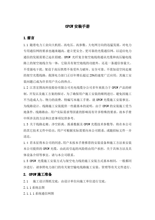
OPGW安装手册1.前言1.1 随着电力工业向大机组、高电压、高参数、大电网方向的迅猛发展,对电力专用通信网的要求也越来越高。
建立更安全、更可靠的光缆通信网,以适应电力通信的发展需要已迫在眉睫。
OPGW光纤复合架空地线将通讯光缆和高压输电线路上的架空地线合为一体,它除具有架空地线的功能外,还是一条通信容量大、不受强电干扰,架设于高压铁塔不易受外力破坏、安全可靠、不需加设空间走廊的架空光缆线路,我国电力部门正以年增长超过25%的速度广泛应用,其施工安装问题已成为许多用户关心的热点。
1.2 江苏宏图高科技股份有限公司光电线缆分公司多年来致力于OPGW产品的研制、开发以及施工方案的探讨,为了确保用户施工安装的顺利进行,避免因施工不当造成人力、物力的浪费,特编写本施工手册,就OPGW光缆施工安装事宜,为线路设计、线路施工安装提供一些最基本的说明,由于OPGW的安装施工受当地条件、线路路由、用户实际需求等因素的影响而有许多特殊的要求,故本手册中所涉及的方法和注意事项仅供参考。
1.3 关于线路走廊、净空距离、弧垂数据及OPGW光缆技术参数等,将在本公司的其它技术文件中给出,用户可根据实际需要向本公司联系,或随招标文件一并送达。
1.4 若未征得本公司的同意,用户未按本手册推荐的安装设备和施工方法来安装本公司提供的OPGW光缆,由此而引起的风险将由用户承担,关于具体方法及具体设备介绍等事宜,请与本公司联系。
1.5 OPGW光缆施工安装方式与架空电力线的施工安装方式基本相同,一般都同步进行,请参照电力部门的有关架空输电线路施工安装、管理等有关文件进行。
2. OPGW施工准备2.1施工设计图纸交底,由设计单位向施工单位进行交底。
2.1.1系统总图2.1.1.1系统通信网图了解整个系统通信网的组成,其中包括各站使用的设备型号及数量,OPGW 的型号、芯数及附件等,掌握系统本身的传输容量,各个中继段的长度等。
2.1.1.2 电路分配系统图了解整个系统通信网的电路分配,详细的电路分配情况包括电话通信、非话业务(电话、数据、传真、图像等)、直达电路、区间通信、分支转接电路、迂回备用电路、专用电路、路由各站设备的详细配置和连接方式。
奥维通信GSM数字光纤直放站操作与安装手册V2.2(201612月)

研发中心资料编号:AW2.000.6023ASAW900A-6002DAX-A/AW900A-6002DBC-43-164-AGSM数字光纤直放站操作与安装手册编制:审核:标准化:批准:文档版本: V2.2数字光纤直放站操作与安装手册V2.2文档修改历史版本更新日期修改核定更新说明文档状态V1.0 20120604 毛燕霞郑巍编制发布V2.0 20160523 王冬裴非全面修改发布V2.1 20160601 王冬裴非增加6.5.6~6.5.8内容发布V2.2 20161201 王冬裴非修订错误发布前言本手册主要介绍了数字光纤直放站和本地调测软件。
着重叙述了该设备的安装、用途、功能、操作及维护。
由于设备会不断更新,功能会不断增加,软件会不断升级,因此本手册的叙述可能与实际使用版本会有所不同。
本手册中的参数、规格、尺寸、重量及其它如有变更,恕不另行通知。
缩略语注释:GSM ——全球移动通信系统(Global System for Mobile Communication)OP ——光纤(Optical Fiber)BTS ——基站传输/发射台(Base Transceiver Station)TX——设备发射端(Transmit)RX——设备接收端(Receive)OMC ——监控维护中心(operation & maintenance center)OMT ——本地调测(operation & maintenance terminal)ATT——电调衰减(attenuation)ALC——自动电平控制(automatic level control)LNA——低噪放(low noise amplifier)ADC——模数转换(analog to digital converter)DAC——数模转换(digital to analog converter)FPGA———现场可编辑门阵列(field programmable gate array)目录一、概述 (6)1.1手册简介 (6)1.2安全注意事项 (7)1.3 装箱清单 (7)二、数字光纤直放站简介 (8)2.1系统简介 (8)2.2简要应用 (9)2.3基本工作原理 (10)2.4 技术特点 (10)2.5 功能介绍 (11)2.6 技术指标 (12)2.6.1光特性 (12)2.6.2射频指标 (12)2.7 接口说明 (13)2.7.1近端机 (13)2.7.2远端机 (15)2.8 接线说明 (16)2.8.1电源线连接 (16)2.8.2 光纤连接 (16)2.8.3 接地 (16)2.8.4 近端监控天线连接 (16)三、数字光纤直放站安装步骤 (17)3.1安装前准备 (17)3.2近端安装 (17)3.3远端安装 (19)3.4 串并联安装 (20)3.4.1 串联方式连接 (20)3.4.2 并联方式连接 (22)3.5安装后试运行 (22)3.5.1 指示灯 (22)3.5.2 输入功率 (22)四、数字光纤直放站各内部模块说明 (23)4.1近端内部模块 (23)4.2远端内部模块 (24)4.3适应光模块介绍 (24)五、数字光纤直放站应用介绍 (26)5.1替代基站应用 (26)5.2扇区阻挡应用 (26)5.3居民小区的应用 (27)5.4风景区的应用 (28)5.5公路长距离覆盖应用 (29)5.6高速铁路优化应用 (29)5.7载波调度功能的应用 (29)六、LMT介绍 (31)6.1操作说明 (32)6.2串口模式调试介绍 (35)6.3网口模式调试介绍 (40)6.3.1 IP地址设置 (40)6.3.2 网口调试 (42)6.4 SMS短信模式调试介绍 (43)6.5接入网管平台 (47)6.6 LMT工具栏功能介绍 (47)6.5.1 CPU复位 (48)6.5.2 固件升级 (48)6.5.3 开站上报 (50)6.5.4 巡检上报 (51)6.5.5 话务统计 (51)6.5.6 工作信道号和工作信道开关 (51)6.5.7 射频信号开关和下行功放开关 (52)6.5.8 上下行衰减 (52)6.5.9 上行AGC与消噪功能 (53)6.5.10 载波调度的设置 (53)6.5.11 自动选频的设置 (54)6.5.12 GSM MODEM和802.3网卡监控方式的设置 (55)七、故障处理 (56)7.1维护与维修注意事项 (56)7.2紧急情况处理 (57)7.3故障处理流程 (58)7.4常见典型故障 (58)一、概述随着我国移动通讯事业的飞速发展,移动通讯的用户量正不断地增加,以至于蜂窝规划越来越小,基站位置越来越低;另一方面,随着城市建设的高层化,高层建筑正不断涌现,由于无线传播的阴影效应,在这些高层建筑的背后或中间常形成移动通讯信号的盲区。
- 1、下载文档前请自行甄别文档内容的完整性,平台不提供额外的编辑、内容补充、找答案等附加服务。
- 2、"仅部分预览"的文档,不可在线预览部分如存在完整性等问题,可反馈申请退款(可完整预览的文档不适用该条件!)。
- 3、如文档侵犯您的权益,请联系客服反馈,我们会尽快为您处理(人工客服工作时间:9:00-18:30)。
2 设备安装..................................................................................................................................... 6
2.1 近端机安装............................................................................................................................................... 6 2.1.1 近端机挂墙安装方式.......................................................................................................................... 6 2.1.2 近端机机柜安装方式.......................................................................................................................... 7
3.2 软件操作................................................................................................................................................. 22 3.2.1 设备监控版本信息........................................................................................................................... 22 3.2.2 本地监控的连接............................................................................................................................... 22 3.2.3 软件基本操作.................................................................................................................................... 25 3.2.4 网管参数界面................................................................................................................................... 25 3.2.5 告警参数界面.................................................................................................................................... 26 3.2.6 设置参数界面.................................................................................................................................... 27 3.2.7 采样参数界面................................................................................................................................... 27 3.2.8 接入网管的基本操作....................................................................................................................... 28
1.2 接口介绍................................................................................................................................................... 3 1.3 状态指示介绍........................................................................................................................................... 5
AW900A-6002A2-(X) AW900A-6002B(C)-YTH3(X)系列
GSM 光纤直放站操作与安装手册
策 划 奥维通信股份有限公司 产品部 **** 奥维通信股份有限公司 地址:沈阳浑南新区高歌路 6 号 邮编:110179 电话:024-83781111 传真:024-83783888 技术支持网站: 电子邮件:cpb@ ****
修改履历
资料版本 V1.0
修订日期 2010/11AS 发布日期:20101122
修订原因 第一次发布
目录
1 产品概述..................................................................................................................................... 1
2.2 远端机安装............................................................................................................................................... 7 2.2.1 远端机挂墙安装方式.......................................................................................................................... 7 2.2.2 远端机抱杆安装方式.......................................................................................................................... 9
3 设备开通................................................................................................................................... 10
3.1 射频调试................................................................................................................................................. 10 3.1.1 光纤直放站一拖一射频调试............................................................................................................ 10 3.1.2 光纤直放站一拖二射频调试............................................................................................................ 13 3.1.3 光纤直放站一拖三射频调试............................................................................................................ 16 3.1.4 光纤直放站一拖四射频调试............................................................................................................ 19
1.3.1 状态指示灯.......................................................................................................................................... 5
4 注意事项................................................................................................................................... 29