E3F-DS30C4 光电开关 说明书
在线组件.com E3F3光电传感器说明书

on e n t s .co mE3F3 Photoelectric Sensor1Threaded Cylindrical Photoelec-tric Sensor with Built-in Amplifi-er for Use as an Optical Proximity SensorHigh Noise-immunity with Photo-IC Technology•Up-to-date photo-IC to increase noise immunity.•M18 DIN-sized cylindrical housing, ABS resin case.•Long sensing distance (30 cm) with sensitivity adjus-tor for diffuse type.•Short-circuit and reverse connection protection.<READ AND UNDERSTAND THIS CATALOG>Please read and understand this catalog before purchasing the products. Please consult yourOMRON representative if you have any questions or comments.Ordering Informationo nl i ne c om p on e n t s .co m2E3F3 Photoelectric Sensor■Model Number Legend■Accessories (Order Separately)Note:E39-R1 is included in E3F3-R @@ and E3F3-R @@M.Specifications■Ratings/CharacteristicsNameModelReflectorE39-R1, E39-R3Reflector (tape type)E39-RS1, E39-RS2, E39-RS3Lens Cap E39-F31Mounting BracketY92E-B18ItemSensing method Through-beam RetroreflectiveDiffuse reflectiveNPN outputE3F3-T11E3F3-R11E3F3-R12E3F3-D11E3F3-D12E3F3-T16E3F3-R16E3F3-R17E3F3-D16E3F3-D17E3F3-T61E3F3-R61E3F3-R62E3F3-D61E3F3-D62E3F3-T66E3F3-R66E3F3-R67E3F3-D66E3F3-D66PNP outputE3F3-T31E3F3-R31E3F3-R32E3F3-D31E3F3-D32E3F3-T36E3F3-R36E3F3-R37E3F3-D36E3F3-D37E3F3-T81E3F3-R81E3F3-R82E3F3-D81E3F3-D82E3F3-T86E3F3-R86E3F3-R87E3F3-D86E3F3-D87Sensing distance 5 m3 m (Non-polarized when us-ing E39-R1) 2 m (Non-polarized when us-ing E39-R1)100 mm 300 mmStandard sensing object Opaque object: 11mm min.Opaque object: 56mm min.100 × 100 mm white mat paperHysteresis---20% max. of sensing distanceLight source (wavelength)Infrared LED (860 mm)Red LED (680 mm)Infrared LED (860 mm)Power supply voltage 12 to 24 VDC ±10%, ripple (p-p): 10% max.Current consumption 45 mA max. (light source and receiver)25 mA max.Control output Open collector transistor output, 100 mA max., residual voltage: 1 V max. at 100 mA Protective circuit Output short-circuit protection, DC power supply reverse polarity protection Response time 1.0 ms max.Sensitivity adjustment ---Single-turn adjusterAmbient illumination Incandescent lamp: 3,000 l x max., Sunlight: 10,000 l x max.Ambient temperature Operating: –25 to 55 °C (with no icing or condensation)Storage: –30 to 70 °C (with no icing or condensation)Ambient humidity Operating: 45% to 85% (with no condensation)Storage: 35% to 95% (with no condensation)Insulation resistance 20 M Ω min. (at 500 VDC) between current carry parts and case Dielectric strength 1,000 VAC at 50/60 Hz for 1 min between current carry parts and case Vibration resistance (destruction)10 to 55 Hz, 1.5-mm double amplitude for 1 hour each in X, Y , and Z directions Shock resistance (destruction)500 m/s 2 for 3 times each in X, Y , and Z directionsDegree of protection IEC 60529 IP66Connecting method Pre-wired (standard length: 2 m)/M12 connectorIndicatorsOperation indicator (orange) [Power indicator of emitter (orange)]Weight Pre-wiredMetal: 200 g max.Metal housing: 100 g max.Plastic: 170 g max.Plastic housing: 85 g max.M12 connectorMetal: 120 g max.Metal housing: 60 g max.Plastic: 40 g max.Plastic housing: 20 g max.Packing Nylon bag MaterialCase Plastic: ABS, Metal: Nickel-brass Lens PMMAAccessoriesScrew nuts: ABS or Nickel-brassAccessoriesScrew nuts (4),Instruction sheetScrew nuts (2),E39-R1 reflector,Instruction sheetScrew nuts (2),Instruction sheetScrew nuts (2),Instruction sheet,Adjusting driverE3F3 Photoelectric Sensor3Engineering Datai m4E3F3 Photoelectric SensorOperation■NPN Output■PNP Outputo e c .co E3F3 Photoelectric Sensor5DimensionsNote:All units are in millimeters unless otherwise indicated.■SensorsNote:Pre-wired Cord:Polyvinyl chloride-covered cord, 4-mm dia. (18/0.12), Standard length: 2 mEmitter: 2-conductor (brown and blue)Receiver and Reflective model: 3-conductor (brown, blue, and black)M12 connector: 1: +V, 2: NC, 3: 0 V, 4: Output2422E3F3-D @249.442.43724E3F3-D @2M422E3F3-D @724E3F3-D @7M2224E3F3-R @2E3F3-D @1247.7E3F3-R @1M E3F3-R @2M E3F3-D @1M2224E3F3-D @62427.7E3F3-D @6Mo nl i ne c om p on e n t s .co m6E3F3 Photoelectric Sensor■Accessories (Order Separately)E39-R3 RetroreflectorE39-RS1 RetroreflectorE39-RS2 Retroreflector1134.819.3T wo, M32.61.2343841.810.125.4+0.11.2T wo, M30.220381.210534R25.416T wo, 3.2 dia.11200.20.214513.7293.4R204.53.4718.4562822.93.4Adhesiveside 25.4Mounting Bracket for E39-K3(Sold Together)E39-RS3 RetroreflectorAdhesive tape sideAdhesive tape sideAdhesive tape sideMaterial: Acrylic resinMaterial: Acrylic resinMaterial: Acrylic resino nl i ne c om p on e n t s .co mE3F3 Photoelectric Sensor7PrecautionsIf the input/output lines of the photoelectric sensor are placed in the same conduit or duct as power lines or high-voltage lines, the photo-electric sensor could be induced to malfunction, or even be dam-aged, by electrical noise. Separate the wiring, or use shielded lines as input/output lines to the photoelectric sensor.Do not subject the photoelectric sensor to excessive shock when mounting, in keeping with IP66 standards.When you use the photoelectric sensor in the vicinity of an inverter motor, be sure to connect the protective ground wire of the motor to ground. Failure to ground the motor may result in malfunction of the sensor.MountingDo not exceed a torque of 20 kgf·cm (2.0 N·m) when tightening mounting nuts.!WARNINGThe E3F3 Photoelectric sensor is not a safety component for en-suring the safety of people as defined by EC Directives (91/386EEC) and covered by separate European standards or by any oth-er regulations or standards.E39-F31 Lens Cap32+0.217 max.718 dia.3047 max.4 max.o nl i ne c om p on e n t s .co mREAD AND UNDERSTAND THIS DOCUMENTPlease read and understand this document before using the products. Please consult your OMRON representative if you have any questions or comments.WARRANTYOMRON’s exclusive warranty is that the products are free from defects in materials and workmanship for a period of one year (or other period if specified) from date of sale by OMRON.OMRON MAKES NO WARRANTY OR REPRESENTATION, EXPRESS OR IMPLIED, REGARDING NON-INFRINGEMENT, MERCHANTABILITY, OR FITNESS FOR PARTICULAR PURPOSE OF THE PRODUCTS. ANY BUYER OR USER ACKNOWLEDGES THAT THE BUYER OR USER ALONE HAS DETERMINED THAT THE PRODUCTS WILL SUITABLY MEET THE REQUIREMENTS OF THEIR INTENDED USE. OMRON DISCLAIMS ALL OTHER WARRANTIES, EXPRESS OR IMPLIED.LIMITATIONS OF LIABILITYOMRON SHALL NOT BE RESPONSIBLE FOR SPECIAL, INDIRECT, OR CONSEQUENTIAL DAMAGES, LOSS OF PROFITS OR COMMERCIAL LOSS IN ANY WAY CONNECTED WITH THE PRODUCTS, WHETHER SUCH CLAIM IS BASED ON CONTRACT, WARRANTY , NEGLIGENCE, OR STRICT LIABILITY .In no event shall responsibility of OMRON for any act exceed the individual price of the product on which liability is asserted.IN NO EVENT SHALL OMRON BE RESPONSIBLE FOR WARRANTY , REPAIR, OR OTHER CLAIMS REGARDING THE PRODUCTS UNLESS OMRON’S ANALYSIS CONFIRMS THAT THE PRODUCTS WERE PROPERLY HANDLED, STORED, INSTALLED, AND MAINTAINED AND NOT SUBJECT TO CONTAMINATION, ABUSE, MISUSE, OR INAPPROPRIATE MODIFICATION OR REPAIR.SUITABILITY FOR USETHE PRODUCTS CONTAINED IN THIS DOCUMENT ARE NOT SAFETY RATED. THEY ARE NOT DESIGNED OR RATED FOR ENSURING SAFETY OF PERSONS, AND SHOULD NOT BE RELIED UPON AS A SAFETY COMPONENT OR PROTECTIVE DEVICE FOR SUCH PURPOSES. Please refer to separate catalogs for OMRON's safety rated products.OMRON shall not be responsible for conformity with any standards, codes, or regulations that apply to the combination of products in the customer’s application or use of the product.At the customer’s request, OMRON will provide applicable third party certification documents identifying ratings and limitations of use that apply to the products. This information by itself is not sufficient for a complete determination of the suitability of the products in combination with the end product, machine, system, or other application or use.The following are some examples of applications for which particular attention must be given. This is not intended to be an exhaustive list of all possible uses of the products, nor is it intended to imply that the uses listed may be suitable for the products:•Outdoor use, uses involving potential chemical contamination or electrical interference, or conditions or uses not described in this document.•Nuclear energy control systems, combustion systems, railroad systems, aviation systems, medical equipment, amusement machines, vehicles, safety equipment,and installations subject to separate industry or government regulations.•Systems, machines, and equipment that could present a risk to life or property.Please know and observe all prohibitions of use applicable to the products.NEVER USE THE PRODUCTS FOR AN APPLICATION INVOLVING SERIOUS RISK TO LIFE OR PROPERTY WITHOUT ENSURING THAT THE SYSTEM AS A WHOLE HAS BEEN DESIGNED TO ADDRESS THE RISKS, AND THAT THE OMRON PRODUCT IS PROPERLY RATED AND INSTALLED FOR THE INTENDED USE WITHIN THE OVERALL EQUIPMENT OR SYSTEM.PERFORMANCE DATAPerformance data given in this document is provided as a guide for the user in determining suitability and does not constitute a warranty. It may represent the result of OMRON’s test conditions, and the users must correlate it to actual application requirements. Actual performance is subject to the OMRON Warranty and Limitations of Liability.CHANGE IN SPECIFICATIONSProduct specifications and accessories may be changed at any time based on improvements and other reasons.It is our practice to change model numbers when published ratings or features are changed, or when significant construction changes are made. However, some specifications of the product may be changed without any notice. When in doubt, special model numbers may be assigned to fix or establish key specifications for your application on your request. Please consult with your OMRON representative at any time to confirm actual specifications of purchased products.DIMENSIONS AND WEIGHTSDimensions and weights are nominal and are not to be used for manufacturing purposes, even when tolerances are shown.ERRORS AND OMISSIONSThe information in this document has been carefully checked and is believed to be accurate; however, no responsibility is assumed for clerical, typographical, or proofreading errors, or omissions.PROGRAMMABLE PRODUCTSOMRON shall not be responsible for the user’s programming of a programmable product, or any consequence thereof.COPYRIGHT AND COPY PERMISSIONThis document shall not be copied for sales or promotions without permission.This document is protected by copyright and is intended solely for use in conjunction with the product. Please notify us before copying or reproducing this document in any manner, for any other purpose. If copying or transmitting this document to another, please copy or transmit it in its entirety.In the interest of product improvement, specifications are subject to change without notice.ALL DIMENSIONS SHOWN ARE IN MILLIMETERS.To convert millimeters into inches, multiply by 0.03937. T o convert grams into ounces, multiply by 0.03527.Cat. No. E365-E1-01OMRON CorporationIndustrial Automation CompanySensing Devices Division H.Q.Industrial Sensors Division Shiokoji Horikawa, Shimogyo-ku,Kyoto, 600-8530 JapanT el: (81)75-344-7022/Fax: (81)75-344-7107Printed in Japan 0605-?M (0605) (?)。
漫反射E3F-DS10C2光电开关说明书

漫反射E3F-DS10C2光电开关说明书产品图片Photo尺寸图Dimension drawing
检测形式X:漫反射
T:0.7(M) 测距可调节
型号漫反射E3F-DS10C2
额定工作电压(纹波峰值
<=15%)[V]DC10 (36V)
AC
输出信号NPN 常开工作电流表晶体管/可控硅/继电[mA]200mA
响应时间[ms]<3
指向角3°...20°电压降晶体管/可控硅/继电器<1.5V
消耗电流[ms]<=20
差动距离<15%
极性保护▲短路保护■▲■
动作指示
工作环境照度LUX 白炽灯(受光面照度)<=3000太阳光(受光面照度)<=10000
工作环境温度-25...+55[℃]外壳材料黄铜镀铬
连接方式Y:引线J:内接线C:插件Y C
防护等级IP67
符合标准GB/T14048.10
电气接线图备注:外形尺寸可按用户要
求生产。
光电开关传感器说明书
光电开关传感器 光电漫反型模拟量传感器
特点: 1 长距离检测,高精度检测 2 可检测小物体 3 不受被检物的形状、颜色和材质影响 4 适用恶劣工作环境
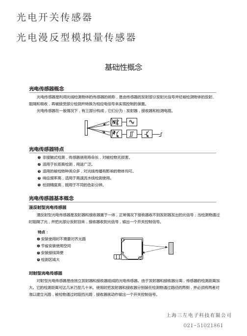
回归反射型光电传感器 回归反射型光电传感器是把发射器和接收器装入同一个装置内,在其前方装一块反光板,利用反射原理完成光电
控制作用的光电传感器。正常情况下,发射器发出的光被反光板反射回来被接收器收到;一旦光路被检测物挡住,接 收器检测的光信号有变化,光电传感器就动作,输出一个开关控制信号。
特点: 1 安装使用时便于光路对齐 2 相对于对射式光电传感器,节省安装使用空间 3 安装接线简便 4 不受被检物的形状、颜色和材质影响
上海三左电子科技有限公司 021-51021861
光电开关传感器 光电漫反型模拟量传感器
应用实例
光电式传感器主要利用光电效应检测物体。 在环境条件比较好、无粉尘污染的场合,可采用光电式传感器。 光电式传感器有检测距离远,对被检测物无影响的特性,广泛用于电子行业、食品饮料行业、包装物流行业等。
检测集成电路块
规格表中的检测距离是在检测目标为100*100mm、200*200mm、300*300mm的白色无光泽纸的条件下测得。
对射型 将发射器和接收器面对面安装,并连接电源。 调节发射器和接收器的上下左右位置,使中心对正,使指示灯状态变化。 可靠安装两者后并校对使其检测到目标。
发射器
回归反射型(包括偏振反射型) 将传感器和反光板镜面对面安装后,连接电源。 调节反射面的上下左右位置,传感器的指示灯状态变化。 可靠安装两者后并校对并使其检测到目标。
光电开关传感器
光电漫反型模拟量传感器
基础性概念
光电传感器概念
E3Z-光电开关说明书
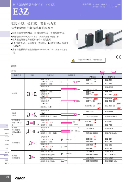
放大器内置型光电开关 (小型)E3Z实现小型、长距离、节省电力和节省能源的光电传感器的标准型■检测距离/对射型15m 、回归反射型4m 、扩散反射型1m 。
■独特的防止外部乱光计算方法,变频荧光灯下也能工作。
■最大限度降低电力消耗和含铅材质的使用。
■IP67保护构造,防止相互干扰功能, EN 规格标准。
防油型 为IP67f 。
■光轴与机械轴的偏差控制在±2.5°\u20197X 内,光轴对合更容 易。
种类相关信息 技术指南 (技术篇) (1290)技术指南 (操作篇) (1400)E3Z 注. 防油型号的回归反射型与标准的回归反射型检测距离不同。
*1. 不附带反射板,根据不同用途,有7种反射板可供选择购买。
*2. 检测距离是使用E39-R1S 时距离。
另外传感器与反射板间的距离请设定在 []内的数值以上的范围。
*3. 上表中标有*3的产品表示有导线0.5m 也是标准品,请在型号末尾标明导线长度。
(例:E3Z-T61 0.5M ) *4. 上表中标有*4的产品表示有接插件中继型 (M12)型号末尾带有-M1J 。
(例:E3Z-T61-M1J ) *5. 上表中标有*5的产品表示e-CON 接插件中继型。
(导线长度0.3m/0.5m/2m )。
型号末尾带有-ECON 。
例如E3Z-□6□-ECON 。
详细情况请参照1381页。
连接接插件有单面e-CON 接插件 E39-ECON □ (导线长度2m/5m )和两端e-CON 接插件 E39 -ECONW □ (导线长度0.5~2m 0.1m 单位) 2种。
e-CON 是FA 设备、连接器制作商的标准化规格。
*6. 备有夹紧式e-CON 接插件中继型 (导线长度2m ) 。
型号末尾带有-ECON-C (例:E3Z-T61-ECON-C 2M ) 。
接插件有单侧e-CON 接插件型 E39-ECON □M (导线长度2m/5m ) 和两端e-CON 接插件型 E39-ECONW □ (导线长度0.5~2m 0.1m 为单位)。
OMRON E3ZM 放大器内置型光电开关(小型) 说明书

E39-L151
⬉ܝӴᛳ఼
E3ZM
数量
备注
Ӵᛳ఼ᣛफ ܝ㑸ᓣ
1 保护外罩固定件 *
ᬒ఼ߚ行ൟ
ᬒ఼ݙ㕂ൟ
1
⬉⑤ݙ㕂ൟ
⫼䗨ߚ㉏
〈传感器调整器〉 可方便地安装到传送带的 ೈ䆒
铝框、导轨,且调整方便
左右调整时
ҟ㒡
1
E39-L44
1 背面安装固定件
注. 对射型的场合请订购2个用于投光器/受光器。 * 不能使用连接器型。
使用湿度范围
运行时:35~85%RH、保存时:35~95%RH(不结露)
绝缘电阻
20MΩ以上 (DC500V兆欧表)
耐电压
AC1,000V 50/60Hz 1min
振动 (耐久)
10~55Hz 双振幅1.5mm X、 Y、 Z各方向 2h
冲击 (耐久)
500m/s2 X、 Y、 Z各方向 3次
保护构造 *1
E3ZM-LS61H E3ZM-LS81H
E3ZM-LS66H E3ZM-LS86H
E3ZM-LS62H E3ZM-LS82H
E3ZM-LS67H E3ZM-LS87H
E3ZM-LS64H E3ZM-LS84H
E3ZM-LS69H E3ZM-LS89H
附件
反射板
名称
E3ZM-R 检测距离 (代表例)*
175
⬉ܝӴᛳ఼
E3ZM
种类
Ӵᛳ఼ᣛफ ܝ㑸ᓣ
ᬒ఼ߚ行ൟ ᬒ఼ݙ㕂ൟ
⬉⑤ݙ㕂ൟ ⫼䗨ߚ㉏ ೈ䆒 ҟ㒡
本体
检测形式
形状
连接方式
检测距离
对射型 *5
导线引出型 (2m)*3 连接器型 (M8·4极)*4 导线引出型 (2m)*3
电感式E3F-DS10C4光电开关说明书

电感式E3F-DS10C4光电开关说明书产品图片Photo尺寸图Dimension drawing
检测形式X:漫反射
T:0.7(M) 测距可调节
型号电感式E3F-DS10C4
额定工作电压(纹波峰值
<=15%)[V]DC10 (36V)
AC
输出信号NPN 常开工作电流表晶体管/可控硅/继电[mA]200mA
响应时间[ms]<3
指向角3°...20°电压降晶体管/可控硅/继电器<1.5V
消耗电流[ms]<=20
差动距离<15%
极性保护▲短路保护■▲■
动作指示
工作环境照度LUX 白炽灯(受光面照度)<=3000太阳光(受光面照度)<=10000
工作环境温度-25...+55[℃]外壳材料黄铜镀铬
连接方式Y:引线J:内接线C:插件Y C
防护等级IP67
符合标准GB/T14048.10
电气接线图备注:外形尺寸可按用户要
求生产。
电子设计大赛智能超车小车 c题

机安装到电动车上需要对电动车模型进行较大改动,不适用于此系统, 故放弃本方案。
方案二: 霍尔传感器测速。 利用霍尔开关元件测转速,内部具有稳压电路、霍尔电势发生器、 放大器、施密特触发器和输出电路,其输出电平和TTL 电平兼容。在待 测旋转体的转轴上装上一个圆盘,在圆盘上装上若干对小磁钢,小磁钢 愈多分辨率越高。霍尔开关固定在小磁钢附近,当旋转体以角速度M 旋 转时,每当一个小磁钢转过霍尔开关,霍尔开关便输出一个脉冲,计算 出单位时间的脉冲数,即可确定旋转体的速度。但是相对于本设计,安 装不便,故本设计放弃此方案。 方案三: 红外测速传感器。 红外测速传感器是传感器开孔圆盘的转轴与转轴相连接,红外线通 过开孔盘的孔和缝隙反射到红外接收头上,开孔盘随旋转体转一周,红 外对射管接收的次数等于盘上的开孔数,从而测出旋转体旋转速度。灵 敏度较高,设计简单,占用空间少。 综上所述,本设计采用方案三。
40cm左右,因而探测距离满足本设计的小车需求。 综上考虑,选用方案四。
1.6 电机选择方案与论证
本系统为智能电动车,对于电动车来说,因此驱动轮的驱动电机的 选择就显得十分重要。由于本实验要实现对路径的准确定位和精确测 量,本设计综合考虑了一下两种方案。
方案一:采用步进电机作为该系统的驱动电机。 步进电机转过的角度可以精确的定位,从而实现小车前进路程和位 置的精确定位。虽然采用步进电机有诸多优点,但是步进电机的输出力 矩较低,随转速的升高而下降,且在较高转速时会急剧下降,其转速较 低,不适用于小车等有一定速度要求的系统。经综合比较考虑,本设计 放弃了此方案。 方案二:采用直流减速电机。 直流减速电机转动力矩大,体积小,重量轻,装配简单,使用方 便。由于其内部由高速电动机提供原始动力,带动变速(减速)齿轮 组,可以产生较大扭力。 为了能够较好的满足系统的要求,本设计选择了方案二。
光电开关说明书

1PhotoelectricsRetro-reflective, Transistor Output Type PMR•Range: 10 m•Modulated, infrared light•Rated operational voltage: 10 to 40 VDC •Output: 200 mA, NPN or PNP•Make or break switching function (switch selectable)•Fully protected•LED-indication for target detected •High immunity to ambient light•25 x 65 x 81 mm reinforced PC housing, IP 67•Timer options (adjustable)Product DescriptionRetro-reflective photoelectric switch. Range up to 10 m.Fix ed sensitivity. High immu-nity to ambient light. Output function switch selectable.Protection degree IP 67.Screw terminal connection.25 x 65 x 81 mm polycarbo-nate housing. PG 13.5 or 1/2"NPT cable gland. Timer op-tions: Delay on operate, delay on release, one shot (triggered on leading or trailing edge).Type SelectionHousing Range Ordering no.Ordering no.Ordering no.Ordering no.W x H x DS nwithout timer without timer with timer with timer NPN PNP NPN PNP 25 x 65 x 81PG 13.5 cable gland 10 m PMR 10N G PMR 10P G PMR 10N GT PMR 10P GT 1/2" NPT cable gland10 mPMR 10N IPMR 10P IPMR 10N ITPMR 10P ITSpecificationsRated operating distance (S n )10 m (0 to 5,000 lux)With reflector type ER 4,ref. targetRated operational volt. (U B )10 to 40 VDC Ripple (U rpp )10%Output currentContinuous (I e )≤200 mA Short-time (I)200 mA,max. load capacity 100 nFNo load supply current ≤40 mA OFF-state current (I r )Max. 100 µA Voltage drop (U d )≤2.5 VDC Transient voltage IEC 947-5-2, level 3, 2.5 kV Dielectric voltage 2000 VAC rms (cont./supply)Sensitivity Fixed Light source GaAlAs, LED, 880 nm Light type Infrared, modulated Optical angle ±2°Light spot size 280 mm at 4 m Operating frequency 100 Hz Response time OFF-ON (t ON )≤4 ms ON-OFF (t OFF )≤6 msTime delay before avail. (t v )≤300 ms (typ. 100 ms)Output function Switch selectable, make or break switching IndicationTarget detected LED, yellow Optional timer Delay on operate 0.1 to 7 s ±2 s Delay on release 0.1 to 7 s ±2 s One shot 0.1 to 7 s ±2 sEnvironmentOvervoltage category III (IEC 664/664A; 947-1)Pollution degree 3 (IEC 664/664A; 947-1)Degree of protection IP 67 (IEC 529; 947-1)Temperature Operating -25°to +55°C (-13°to +131°F)Storage -30°to +80°C (-22°to +176°F)Vibration 10 to 150 Hz, 0.5 mm/7.5 g (IEC 68-2-6)Shock2 x 1 m & 100 x 0.5 m (IEC 68-2-32)Rated insulation voltage 50 VAC (rms)Electrical protectionShort-circuit, reverse polarity,overvoltage, transients2PMRSpecifications (cont.)Selection of FunctionSwitch 1 2 3PMR ... .PMR ... .T1 Break switching 9 One shot, leading edge - Break switching8 One shot, trailing edge - Make switching7 One shot, trailing edge - Break switching 5 Delay on release - Break switching 3 Delay on operate - Break switching 10One shot, leading edge - Make switching2 Make switching4 Delay on operate - Make switching 6 Delay on release - Make switching Don't careUpper postion ON (Mode 1)Lower position OFF (Mode 0)Housing material Body PC, grey Front PC, black CoverPC, blackCable glandPA, black, reinforced Mounting bracket Steel, blackConnection Screw terminal 5 x 2 x 1 mm 2Cable gland PG 13.5 or 1/2" NPT for cable 6 to 10 mm Weight90 gConnection DiagramTruth TableAccessoriesDelivery Contents•Photoelectric switch: PMR •Cable gland•Installation instruction •Mounting bracket•Packaging:Corrugated cardboard (environmentally friendly recycling material)•Reflectors: ER series•MB02 mounting bracket 90 mm long for mounting PMR from behind3PMROperation Diagramt = Time delaytv = Power ON delayDimensionsPMRPMR with angle bracketo r 1/2" N P TLED indication。
- 1、下载文档前请自行甄别文档内容的完整性,平台不提供额外的编辑、内容补充、找答案等附加服务。
- 2、"仅部分预览"的文档,不可在线预览部分如存在完整性等问题,可反馈申请退款(可完整预览的文档不适用该条件!)。
- 3、如文档侵犯您的权益,请联系客服反馈,我们会尽快为您处理(人工客服工作时间:9:00-18:30)。
E3F-DS30C4光电开关说明书
产品图片Photo尺寸图Dimension drawing
检测形式X:漫反射
T:0.7(M) 测距可调节
型号E3F-DS30C4
额定工作电压(纹波峰值
<=15%)[V]DC10 (36V)
AC
输出信号NPN 常开工作电流表晶体管/可控硅/继电[mA]200mA
响应时间[ms]<3
指向角3°...20°电压降晶体管/可控硅/继电器<1.5V
消耗电流[ms]<=20
差动距离<15%
极性保护▲短路保护■▲■
动作指示
工作环境照度LUX 白炽灯(受光面照度)<=3000太阳光(受光面照度)<=10000
工作环境温度-25...+55[℃]外壳材料黄铜镀铬
连接方式Y:引线J:内接线C:插
件
Y C
防护等级IP67
符合标准GB/T14048.10
电气接线图备注:外形尺寸可按用户要求生
产。