光电开关说明书
欧姆龙光电开关说明书

欧姆龙光电开关说明书1. 引言欧姆龙光电开关是一种利用光电传感器技术实现的开关设备,通过检测光线的变化来判断是否触发开关动作。
本说明书将详细介绍欧姆龙光电开关的技术原理、使用方法、注意事项以及维护保养等内容,以帮助用户合理、安全地使用该设备。
2. 技术原理欧姆龙光电开关采用了光电传感器技术,在光电传感器中,包含了一对光源和光敏元件。
当遮挡物体经过检测区域时,光敏元件将接收到的光信号发生变化,从而触发开关动作。
光电开关通常有两种工作方式:逻辑输出和模拟输出,具体的输出信号可以根据用户需求进行设置。
3. 使用方法a)安装根据实际需求,将光电开关安装到需要检测的位置上,确保光敏元件可以正常接收到被检测物体通过的光信号。
注意避免外部光源对光敏元件产生干扰,可以通过合理选择安装位置和使用遮光罩等方式来减少干扰。
b)连接将光电开关与电路连接,确保电路连接正确且稳定。
通常光电开关需要使用直流电源进行供电,电压范围根据具体型号来确定。
c)设置根据实际应用需求,设置光电开关的工作方式、触发灵敏度等参数。
欧姆龙光电开关通常提供了相应的参数调节装置,用户可以根据需要进行调整。
d)测试完成安装、连接和设置后,进行测试以确保光电开关正常工作。
可以通过手动触发被检测物体通过检测区域,观察开关的触发情况,根据实际需求进行调整。
4. 注意事项a)使用过程中请确保电源电压符合设备要求,避免超过额定电压范围。
b)在使用过程中请避免将光电开关安装在高温、潮湿等有害环境中,以免影响设备的正常工作。
c)避免遮挡光敏元件,在使用过程中请确保光敏元件处于正常工作状态,避免被阻挡物体遮挡。
d)避免外部光源干扰,在安装过程中请注意避免强光直射到光敏元件上,可以使用遮光罩等方式来减少光源干扰。
e)检查设备连接是否牢固,确保所有连接处都紧固可靠,避免松动引起的工作异常。
f)如设备出现故障,请及时联系专业维修人员进行处理,避免私自拆解修理。
5. 维护保养a)定期清洁光敏元件,可以使用干净的棉签轻轻擦拭。
E3Z-光电开关说明书
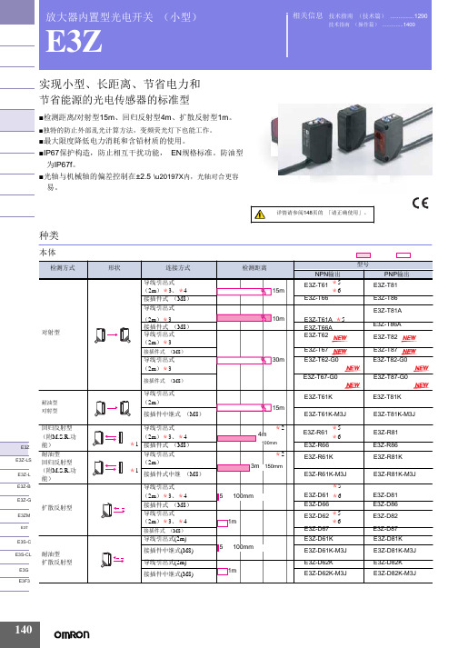
放大器内置型光电开关 (小型)E3Z实现小型、长距离、节省电力和节省能源的光电传感器的标准型■检测距离/对射型15m 、回归反射型4m 、扩散反射型1m 。
■独特的防止外部乱光计算方法,变频荧光灯下也能工作。
■最大限度降低电力消耗和含铅材质的使用。
■IP67保护构造,防止相互干扰功能, EN 规格标准。
防油型 为IP67f 。
■光轴与机械轴的偏差控制在±2.5°\u20197X 内,光轴对合更容 易。
种类相关信息 技术指南 (技术篇) (1290)技术指南 (操作篇) (1400)E3Z 注. 防油型号的回归反射型与标准的回归反射型检测距离不同。
*1. 不附带反射板,根据不同用途,有7种反射板可供选择购买。
*2. 检测距离是使用E39-R1S 时距离。
另外传感器与反射板间的距离请设定在 []内的数值以上的范围。
*3. 上表中标有*3的产品表示有导线0.5m 也是标准品,请在型号末尾标明导线长度。
(例:E3Z-T61 0.5M ) *4. 上表中标有*4的产品表示有接插件中继型 (M12)型号末尾带有-M1J 。
(例:E3Z-T61-M1J ) *5. 上表中标有*5的产品表示e-CON 接插件中继型。
(导线长度0.3m/0.5m/2m )。
型号末尾带有-ECON 。
例如E3Z-□6□-ECON 。
详细情况请参照1381页。
连接接插件有单面e-CON 接插件 E39-ECON □ (导线长度2m/5m )和两端e-CON 接插件 E39 -ECONW □ (导线长度0.5~2m 0.1m 单位) 2种。
e-CON 是FA 设备、连接器制作商的标准化规格。
*6. 备有夹紧式e-CON 接插件中继型 (导线长度2m ) 。
型号末尾带有-ECON-C (例:E3Z-T61-ECON-C 2M ) 。
接插件有单侧e-CON 接插件型 E39-ECON □M (导线长度2m/5m ) 和两端e-CON 接插件型 E39-ECONW □ (导线长度0.5~2m 0.1m 为单位)。
欧姆龙光电开关说明书

欧姆龙光电开关说明书欧姆龙光电开关说明书欧姆龙光电开关是一种智能化的电子元件,其主要作用是通过光电原理进行物体检测和位置控制。
本说明书将详细介绍欧姆龙光电开关的特点、工作原理、应用场景及使用方法。
一、特点:1.欧姆龙光电开关是一种高精度、高稳定性、可靠性极强的电子元件。
2.具有光电隔离、噪声抑制、防护等多种功能,适用于各种复杂环境。
3.采用LED和光敏二极管作为光电转换元件,光电效率高,响应速度快。
4.外部封装材料采用耐磨损、耐腐蚀等工程塑料,有很好的耐用性。
二、工作原理:欧姆龙光电开关通过内部光电器件产生光束,当光束遇到物体时,被物体反射后重新聚焦到另一端的光电器件中,从而完成物体的检测。
欧姆龙光电开关具有光电隔离功能,内部电路和外部电路之间采用光耦隔离,有效地防止外部杂音对内部电路造成的干扰。
三、应用场景:欧姆龙光电开关广泛应用于机械、自动化控制、制造业等领域,主要用于非接触式物体检测、位置控制、安全门的监测等方面。
1.非接触式物体检测:无需接触被检测物体,避免了传统机械开关导致的松动、震动等问题,可以检测各种形状、大小、材质的物体。
2.位置控制:通过欧姆龙光电开关的探头来确认物体的位置,可以实现高精度的位置控制。
3.安全门监测:应用于工业机器人、机床等设备的安全门监测,如果关门后开关没有断开,则不允许机器运转,保证工作安全。
四、使用方法:欧姆龙光电开关使用便捷,安装简单。
1.安装:根据欧姆龙光电开关的不同型号和尺寸进行选型,将开关固定在合适的位置,光电探头对准被检测物体即可。
2.电路连接:按照说明书的接线图进行连接,注意接口与电压等参数的匹配。
3.调试:路电线接好后进行检测,根据不同的检测需求进行参数调整,使光电开关的工作符合工作要求。
总之,欧姆龙光电开关是一种高精度、高稳定、安全可靠的电子元件,在工业、汽车、航空等领域中得到了广泛的应用。
相信在未来的发展中,欧姆龙光电开关会继续引领各领域的技术发展和应用进步,推动人类社会的不断发展。
电感式E3F-DS10C4光电开关说明书

电感式E3F-DS10C4光电开关说明书产品图片Photo尺寸图Dimension drawing
检测形式X:漫反射
T:0.7(M) 测距可调节
型号电感式E3F-DS10C4
额定工作电压(纹波峰值
<=15%)[V]DC10 (36V)
AC
输出信号NPN 常开工作电流表晶体管/可控硅/继电[mA]200mA
响应时间[ms]<3
指向角3°...20°电压降晶体管/可控硅/继电器<1.5V
消耗电流[ms]<=20
差动距离<15%
极性保护▲短路保护■▲■
动作指示
工作环境照度LUX 白炽灯(受光面照度)<=3000太阳光(受光面照度)<=10000
工作环境温度-25...+55[℃]外壳材料黄铜镀铬
连接方式Y:引线J:内接线C:插件Y C
防护等级IP67
符合标准GB/T14048.10
电气接线图备注:外形尺寸可按用户要
求生产。
ZS-46系列光电开关 安装手册说明书
2 Summary of Product parts3 SpecificationsRefer to the operation manual on SMC website (URL ).InstallationMounting with bracketMount the bracket to the body with mounting screws (Self tappingscrews: Nominal size 3 x 8L (2 pcs)), then set the body to the specified position.∗: Tighten the bracket mounting screws to a torque of 0.5±0.05 Nm.Self tapping screws are used, and should not be re-used several times.(Option)∗: The panel mount adapter can be rotated through 90 degrees for mounting.•Bracket A (Part No.: ZS-46-A1)•Bracket B (Part No.: ZS-46-A2)WiringWiring connectionsConnections should be made with the power supply turned e a separate route for the product wiring and any power or high voltage wiring. Otherwise, malfunction may result due to noise.If a commercially available switching power supply is used, be sure to ground the frame ground (FG) terminal. If the switching power supply is connected for use, switching noise will be superimposed and it will not be able to meet the product specifications. In that case, insert a noise filter such as a line noise filter/ferrite between the switching power supplies or change the switching power supply to the series power supply.How to Use ConnectorConnector attachment/detachment When connecting theconnector, insert it straight onto the pins, holding the lever and connector body, and lock the connector by pushing the lever hook into the concave groove on the housing.To detach the connector,remove the hook from the groove by pressing the lever downward, and pull theconnector straight out.DC(+) Brown 5Pin No.OUT1 Black 4NC 3NC 2DC(-) Blue 1PipingTightening the connection threadFor connecting to the body (piping specification: -M5)After hand tightening, apply a spanner of the correct size to the spanner flats of the piping body, and tighten with a 1/6 to 1/4 rotation.As a reference, the tightening torque is 1 to 1.5 Nm.-NNPN open collector 1 output Max. 28 V, 80 mAResidual voltage: 1 V or lessbuttonNames of individual parts4 Mounting and InstallationRefer to the operation manual on the SMC website (URL ).When tightening, do not hold the Z/ISE20 body with a spanner.Connector pin numbers Installation & Maintenance Manual Digital Pressure Switch Series ZSE20(F)/ISE20This manual contains essential information for the protection of users and others from possible injury and/or equipment damage.•Read this manual before using the product, to ensure correct handling,and read the manuals of related apparatus before use.•Keep this manual in a safe place for future reference.•These instructions indicate the level of potential hazard by label of "Caution", "Warning" or "Danger", followed by important safety information which must be carefully followed.•To ensure safety of personnel and equipment the safety instructions in this manual and the product catalogue must be observed, along with other relevant safety practices.This product is class A equipment that is intended for use in an industrial environment.There may be potential difficulties in ensuring electromagneticcompatibility in other environments due to conducted as well as radiated disturbances.WarningDo not disassemble, modify (including changing the printed circuit board) or repair.An injury or failure can result.Do not operate the product outside of the specifications.Do not use for flammable or harmful fluids.Fire, malfunction, or damage to the product can result.Verify the specifications before use.Do not operate in an atmosphere containing flammable or explosive gases.Fire or an explosion can result.This product is not designed to be explosion proof.Do not use the product in a place where static electricity is a problem.Otherwise it can cause failure or malfunction of the system.If using the product in an interlocking circuit:•Provide a double interlocking system, for example a mechanical system•Check the product regularly for proper operation Otherwise malfunction can result, causing an accident.The following instructions must be followed during maintenance:•Turn off the power supply•Stop the air supply, exhaust the residual pressure and verify that the air is released before performing maintenance work Otherwise an injury can result.CautionDo not touch the terminals and connectors while the power is on.Otherwise electric shock, malfunction or damage to the product can result.After maintenance is complete, perform appropriate functional inspections and leak tests.Stop operation if the equipment does not function properly or there is a leakage of fluid.When leakage occurs from parts other than the piping, the product might be faulty.Disconnect the power supply and stop the fluid supply.Do not apply fluid under leaking conditions.Safety cannot be assured in the case of unexpected malfunction.Refer to the operation manual on the SMC website (URL ).12 to24 VDC-PPNP open collector 1 output Max. 80 mAResidual voltage: 1 V or less12 to 24 VDCPiping specification: -01, -N01After hand tightening, hold the hexagonal spanner flats of the pressure port with a spanner, and tighten with 2 to 3 rotations.As a reference, the tightening torque is 3 to 5 Nm.Mounting with panel mount adapterMount part (a) to the front of the body and fix it. Then insert the body with (a) into the panel until (a) comes into contact with the panel front surface. Next, mount part (b) to the body from the rear and insert it until (b) comes into contact with the panel for fixing.•Panel mount adapter (Part No.: ZS-46-B)Front protective cover(Part No.: ZS-46-D)Power is supplied.button ∗:The outputs will continue to operate during setting.∗:If a button operation is not performed for 3 seconds during the setting, thedisplay will flash. (This is to prevent the setting from remaining incomplete if, for instance, an operator were to leave during setting.)∗:3 step setting mode, simple setting mode and function selection mode settings are reflected each other.5 Outline of Settings [Measurement mode]Operation light: Displays the switch operating condition.LCD display: Displays the current status of pressure, setting mode, selecteddisplay units and error code.4 types of display can be selected for the main display: Single colour of constant red or green; or switching from red to green or green to red corresponding to the output.The indication for the sub display is orange.button: Increases mode and ON/OFF set values.button: Decreases mode and ON/OFF set values.button: Press this button to change mode and to confirm settings.Unit display: Indicates the units currently selected.(Only for display units of kPa and MPa.)Internal circuit and wiring example[F 0] Units conversion functionFunction selection modebutton between 3 and 5 seconds, todisplay [F 0]. Select to display the function to be changed [F]. Pressand hold the button for 2 seconds or longer in function selection mode toreturn to measurement mode.∗:Some products do not have all the functions. If no function is available or selecteddue to configuration of other functions, [- - -] is displayed on the sub display (right).[F 1] Setting of OUT1Refer to the operation manual on the SMC website(URL ).Other parameter settingsDefault SettingThe default setting is as follows.If no problem is caused by this setting, keep these settings.button between 1 and 3 seconds in measurementmode. [SEt] is displayed on the main display. When the button isreleased while in the [SEt] display, the current pressure value isdisplayed on the main display, [P_1] or [n_1] is displayed on the subdisplay (left), and the set value is displayed on the sub display (right)(Flashing).[3 step setting mode (hysteresis mode)]In the 3 step setting mode, the set value (P_1 or n_1) and hysteresis(H_1) can be changed. Set the items on the sub display (set value orhysteresis) with or button. When changing the set value, followthe operation below. The hysteresis setting can be changed in the sameway.(1) Press the button once when the item to be changed is displayedon the sub display.The set value on the sub display (right) will start flashing.(2) Press the or button to change the set value.button and can be reducedbutton.buttons are pressed and heldsimultaneously for 1 second or longer, the set value is displayed as[- - -], and the set value will be the same as the current pressure valueautomatically (snap shot function). Afterwards, it is possible to adjustor button.(3) Press the button to complete the setting.The Pressure switch turns on within a set pressure range (from P1L toP1H) during window comparator mode.Set P1L, the lower limit of the switch operation, and P1H, the upper limitof the switch operation and WH1 (hysteresis) following the instructionsgiven above.(When reversed output is selected, the sub display (left) shows [n1L] and[n1H].)∗:Setting of the normal/reverse output switching and hysteresis/window comparatormode switching are performed with the function selection mode [F 1] OUT1setting.or button, and press the button toset the value. Then, the setting moves to hysteresis setting.(The Snap shot function can be used.)or button, and press the button toset the value. Then, the setting moves to the delay time of the switchoutput.(The Snap shot function can be used.)(4) Press the or button, the delay time of the switch output can beselected.Delay time setting can prevent the output from chattering.(5) Press the button for 2 seconds or longer to complete the OUT1setting.∗:If the button is pressed for less than 2 seconds, the setting will bereturned to P_1.In the window comparator mode, set P1L, the lower limit of the switchoperation, and P1H, the upper limit of the switch operation, WH1 (hysteresis)and dt1 (delay time) following the instructions given above.(When reversed output is selected, the sub display (left) shows [n1L] and[n1H].)How to reset the product after a power cut or forcible de-energizingThe setting of the product will be retained as it was before a power cut orde-energizing. The output condition is also basically recovered to thatbefore a power cut or de-energizing, but may change depending on theoperating environment. Therefore, check the safety of the wholeinstallation before operating the product. If the installation is usingaccurate control, wait until the product has warmed up (approximately 10to 15 minutes).12 Outline with Dimensions (mm)Refer to the operation manual on the SMC website(URL ).11 How to orderRefer to the operation manual on the SMC website(URL ).Peak/bottom value indicationThe maximum (minimum) pressure when the power is supplied is detectedand updated.The value can be displayed on the sub display by pressing orbutton in measurement mode.Snap shot functionThe current pressure value can be stored to the switch output ON/OFF setpoint.buttonsfor 1 second or longer simultaneously. Then, the set value of the subdisplay (right) shows [- - -], and the values corresponding to the currentpressure values are automatically displayed.Zero-clear functionbuttons are pressed for 1second or longer simultaneously, the main display shows [- - -], and thereset to zero.The display returns to measurement mode automatically.Key-lock functionRefer to the operation manual on the SMC website(URL ).14 TroubleshootingError indication functionThis function is to display error location and content when a problem orerror has occurred.other than above are displayed, please contact SMC.Refer to the operation manual on the SMC website(URL ).URL (Global) (Europe)Specifications are subject to change without prior notice from the manufacturer.© 2015 SMC Corporation All Rights Reserved15 ContactsAUSTRIA(43) 2262 62280-0NETHERLANDS(31) 20 531 8888BELGIUM(32) 3 355 1464NORWAY(47) 67 12 90 20CZECH REP.(420) 541 424 611POLAND(48) 22 211 9600DENMARK(45) 7025 2900PORTUGAL(351) 21 471 1880FINLAND(358) 207 513513SLOVAKIA(421) 2 444 56725FRANCE(33) 1 6476 1000SLOVENIA(386) 73 885 412GERMANY(49) 6103 4020SPAIN(34) 945 184 100GREECE(30) 210 271 7265SWEDEN(46) 8 603 1200HUNGARY(36) 23 511 390SWITZERLAND(41) 52 396 3131IRELAND(353) 1 403 9000UNITED KINGDOM(44) 1908 563888ITALY(39) 02 92711BULGARIA(359) 2 974 4492ESTONIA(372) 651 0370ROMANIA(40) 21 320 5111LATVIA(371) 781 77 00LITHUANIA(370) 5 264 8126 Refer to the operation manual on the SMC website(URL ).Default SettingsWhen the pressure exceeds the set value, the switch will be turned on.When the pressure falls below the set value by the amount of hysteresisor more, the switch will be turned off. The default setting is to turn on thepressure switch when the pressure reaches the centre of the atmosphericpressure and upper limit of the rated pressure range. If this condition,shown to the right, is acceptable, then keep these settings.Switch ONAt normal outputSwitch OFFSet valueP_1HysteresisH_1TimePressure。
光电开关说明书

1PhotoelectricsRetro-reflective, Transistor Output Type PMR•Range: 10 m•Modulated, infrared light•Rated operational voltage: 10 to 40 VDC •Output: 200 mA, NPN or PNP•Make or break switching function (switch selectable)•Fully protected•LED-indication for target detected •High immunity to ambient light•25 x 65 x 81 mm reinforced PC housing, IP 67•Timer options (adjustable)Product DescriptionRetro-reflective photoelectric switch. Range up to 10 m.Fix ed sensitivity. High immu-nity to ambient light. Output function switch selectable.Protection degree IP 67.Screw terminal connection.25 x 65 x 81 mm polycarbo-nate housing. PG 13.5 or 1/2"NPT cable gland. Timer op-tions: Delay on operate, delay on release, one shot (triggered on leading or trailing edge).Type SelectionHousing Range Ordering no.Ordering no.Ordering no.Ordering no.W x H x DS nwithout timer without timer with timer with timer NPN PNP NPN PNP 25 x 65 x 81PG 13.5 cable gland 10 m PMR 10N G PMR 10P G PMR 10N GT PMR 10P GT 1/2" NPT cable gland10 mPMR 10N IPMR 10P IPMR 10N ITPMR 10P ITSpecificationsRated operating distance (S n )10 m (0 to 5,000 lux)With reflector type ER 4,ref. targetRated operational volt. (U B )10 to 40 VDC Ripple (U rpp )10%Output currentContinuous (I e )≤200 mA Short-time (I)200 mA,max. load capacity 100 nFNo load supply current ≤40 mA OFF-state current (I r )Max. 100 µA Voltage drop (U d )≤2.5 VDC Transient voltage IEC 947-5-2, level 3, 2.5 kV Dielectric voltage 2000 VAC rms (cont./supply)Sensitivity Fixed Light source GaAlAs, LED, 880 nm Light type Infrared, modulated Optical angle ±2°Light spot size 280 mm at 4 m Operating frequency 100 Hz Response time OFF-ON (t ON )≤4 ms ON-OFF (t OFF )≤6 msTime delay before avail. (t v )≤300 ms (typ. 100 ms)Output function Switch selectable, make or break switching IndicationTarget detected LED, yellow Optional timer Delay on operate 0.1 to 7 s ±2 s Delay on release 0.1 to 7 s ±2 s One shot 0.1 to 7 s ±2 sEnvironmentOvervoltage category III (IEC 664/664A; 947-1)Pollution degree 3 (IEC 664/664A; 947-1)Degree of protection IP 67 (IEC 529; 947-1)Temperature Operating -25°to +55°C (-13°to +131°F)Storage -30°to +80°C (-22°to +176°F)Vibration 10 to 150 Hz, 0.5 mm/7.5 g (IEC 68-2-6)Shock2 x 1 m & 100 x 0.5 m (IEC 68-2-32)Rated insulation voltage 50 VAC (rms)Electrical protectionShort-circuit, reverse polarity,overvoltage, transients2PMRSpecifications (cont.)Selection of FunctionSwitch 1 2 3PMR ... .PMR ... .T1 Break switching 9 One shot, leading edge - Break switching8 One shot, trailing edge - Make switching7 One shot, trailing edge - Break switching 5 Delay on release - Break switching 3 Delay on operate - Break switching 10One shot, leading edge - Make switching2 Make switching4 Delay on operate - Make switching 6 Delay on release - Make switching Don't careUpper postion ON (Mode 1)Lower position OFF (Mode 0)Housing material Body PC, grey Front PC, black CoverPC, blackCable glandPA, black, reinforced Mounting bracket Steel, blackConnection Screw terminal 5 x 2 x 1 mm 2Cable gland PG 13.5 or 1/2" NPT for cable 6 to 10 mm Weight90 gConnection DiagramTruth TableAccessoriesDelivery Contents•Photoelectric switch: PMR •Cable gland•Installation instruction •Mounting bracket•Packaging:Corrugated cardboard (environmentally friendly recycling material)•Reflectors: ER series•MB02 mounting bracket 90 mm long for mounting PMR from behind3PMROperation Diagramt = Time delaytv = Power ON delayDimensionsPMRPMR with angle bracketo r 1/2" N P TLED indication。
光电开关说明书
(mm)
d d
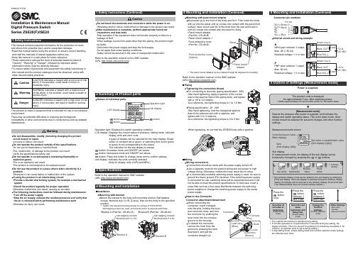
SLS(有 光 泽) 铝轮 (背 面无光泽)
100% 70%
■维护和检修
为使光电开关长期稳定工作,和一般的控制器一样,请进行下列定期检查; (1)检查检测物体和光电开关的安装位置有无偏移、松动、变形。 (2)检查配线、连接部位有无松动、接触不良和断线。 (3)检查检测面有无附粘金属粉尘等堆积物。 (4)检查使用温度、周围环境条件有无异常。
黑碳 白画纸 有光泽物体
100 50
白画 纸
黑碳
30% 35 40
0
5
10
15
20
25
30
检测物体边长d(mm)
(灵敏度旋钮调至最大)
▲
请不要用大力拉传 感器的电源线。
请不要用硬的物体 击检测面。
▲
★ 透过型、反馈反射型光电开关设定距离应小于铭牌上的额定检测距离,应留有余量, 当大于额定检测距离时也能工作,但性能不能保证。另外,在有垃圾和尘埃的恶劣 环境中,检测距离设定时也应小于额定检测距离。 ★ 采用透过型光电开关时,最小检测物体的大小由透镜直径和接收器、发射器安装斜 度来决定。 ★ 漫反射型光电开关铭牌上的检测距离是相对于标准被测物体而言的,实际的检测距 离因被测物体大小、颜色及表面的凹凸状况不同会有所变化,检测距离应设定在额 定检测距离之内。
(8)直流四、五线继电器输出型
Sensor
DC12~240V AC24~240V (1) (2) 电 源 棕 DC10~36V AC90~250V 电源
)
工作距离远,可设定一段很长的工作 距离。
Sensor
兰 Tc 白
Sensor
(2)
电源
E3Z-光电开关说明书
实现小型、长距离、节省电力和节省能源的光电传感器的标准型■检测距离/对射型15m 、回归反射型4m 、扩散反射型1m 。
■独特的防止外部乱光计算方法,变频荧光灯下也能工作。
■最大限度降低电力消耗和含铅材质的使用。
■IP67保护构造,防止相互干扰功能, EN 规格标准。
防油型为IP67f 。
■光轴与机械轴的偏差控制在±2.5°\u20197X 内,光轴对合更容相关信息 技术指南 (技术篇)技术指南 (操作篇) (1400)详情请参阅148页的 「请正确使用」。
E3Z-T61K-M3JE3Z-T81K-M3J回归反射型(附M .S .R.功导线引出式(2m)*3、*44m *2E3Z-R61*5*6E3Z-R81E3Z E3Z-LSE3Z-L E3Z-B能)耐油型回归反射型(附M.S.R.功能)*1*1接插件式(M8)导线引出式(2m)接插件式中继(M8)导线引出式100mm*23m 150mmE3Z-R66E3Z-R61KE3Z-R61K-M3J*5E3Z-R86E3Z-R81KE3Z-R81K-M3JE3Z-GE3ZM E3T 扩散反射型(2m)*3、*4接插件式(M8)导线引出式(2m)*3、*4接插件式(M8)5 100mm1mE3Z-D61E3Z-D66E3Z-D62E3Z-D67*6*5*6E3Z-D81E3Z-D86E3Z-D82E3Z-D87E3S-CE3S-CLE3G E3F3耐油型扩散反射型导线引出式(2m)接插件中继式(M8)导线引出式(2m)接插件中继式(M8)5 100mm1mE3Z-D61KE3Z-D61K-M3JE3Z-D62KE3Z-D62K-M3JE3Z-D81KE3Z-D81K-M3JE3Z-D82K E3Z-D82K-M3J(无M.S.R 功能)→164页接插件式(M8)导线引出式(2m)*3接插件式(M8)500mm 80mm*22m 500mmE3Z-L66E3Z-B61 *5E3Z-B66E3Z-B62 *5E3ZE3Z-B81E3Z-B86E3Z-B82E3Z-B87E3Z-G61-M3J E3Z-G81-M3J附件 (另售)狭缝检测距离 (代表例)狭缝宽度 φ0.5mmφ1mmφ2mm0.5×10mm 1×10mm2×10mm反射板名称E3Z-T □□时50mm200m m800mm 1m2.2mE3Z-R E3Z-T□□A时35mm150mm550mm700mm1.5m3.5m电小检测距离(代表例)φ0.2mmφ0.4mmφ0.7mmφ0.2mmφ0.5mmφ0.8mm型号数量型号E39-S65AE39-S65BE39-S65CE39-S65DE39-S65EE39-S65F备注数量投/受光器各1个E3Z反射板防露导线型小型反射板薄片型反射板检测距离(代表例)*3m 〔100mm〕〔额定值〕4m 〔100mm〕〔额定值〕5m 〔100mm〕2.5m 〔100mm〕3.5m 〔100mm〕3m 〔100mm〕1.5m 〔50mm〕700mm 〔150mm〕1.1m 〔150mm〕1.4m 〔150mm〕E39-R1E39-R1SE39-R2E39-R9E39-R10E39-R1KE39-R3E39-RS1E39-RS2E39-RS31个1个1个1个1个1个1个1枚1枚1枚・回归反射型中不附带反射板・M.S.R.有镜面反射功能E3Z-LSE3Z-LE3Z-BE3Z-GE3ZME3TE3S-C注1. 使用额定值以外的反射板,检测距离以代表例的0.7倍来设定。
光电开关使用说明书
光电开关使用说明书1. 产品介绍光电开关是一种基于光电传感技术的装置,可通过光电感应实现物体的检测和控制。
本产品采用先进的光电技术和高品质材料制造而成,具有高精度、可靠性以及防水防尘的特点。
2. 安装步骤2.1 准备工作在安装光电开关之前,请检查以下事项:- 确保供电电压符合产品规定的电压要求;- 准备好所需的安装工具(如螺丝刀、扳手等);- 学习了解产品的操作手册和安装要求。
2.2 安装位置选择根据实际需要,选择合适的安装位置。
光电开关可以安装在墙壁、天花板或地面上,确保与被控对象的距离和视线畅通。
2.3 连接电源和设备根据产品说明书,正确连接光电开关的电源和被控设备。
请注意正负极的连接,确保电源稳定和可靠。
2.4 调整参数根据具体情况,通过光电开关上的参数调节旋钮,调整灵敏度和触发范围。
根据需要,您还可以调整工作方式(如常开或常闭)。
3. 使用方法3.1 启用光电开关在完成安装和调整后,请确保光电开关与电源连接正常,并保证供电稳定。
打开电源,光电开关将开始正常工作。
3.2 检测和触发根据您的具体需求,将待检测物体放置在光电开关的检测范围内。
当物体进入或离开检测范围时,光电开关将根据调整的参数进行触发,并输出相应的信号。
3.3 注意事项- 避免将光电开关安装在高温、潮湿或易受振动的环境中,以免影响产品的性能和寿命;- 定期检查和清洁光电开关,确保其表面干净,并清除可能影响传感器工作的灰尘或污垢;- 在使用过程中,如发现光电开关存在性能问题或异常情况,请立即停止使用,并联系售后服务中心进行检修或更换。
4. 维护和保养为了确保光电开关的正常工作和延长其使用寿命,请定期进行维护和保养:- 检查电源线和连接器是否牢固;- 清洁传感器和接收器的镜头,避免积灰和污垢的影响;- 定期校准光电开关的参数和灵敏度,以保证其工作精度。
请根据您的具体产品型号和使用情况,详细阅读产品说明书,并按照要求进行正确的安装、调整和使用。
LLS-30光电开关使用说明书090519
LLS-30光电开关使用说明书
LLS-30光电开关具有开关动作响应迅速,使用灵活,抗电磁干扰能力强的特点。
可直接驱动继电器等感性负载。
LLS-30光电开关有很宽的电压适应范围,以满足不同场合的使用要求。
且具有输出短路保护及自恢复功能,可避免在安装、调试过程中,因负载短路引起的损伤。
改变负载的连接方式(负载连接到电源的正极或负极),可实现 NPN输出或 PNP 输出的转换;改变电源的极性,可实现输出方式为亮动(L/ON)或暗动(D/ON)的转换。
外形尺寸如右图所示:
z电缆长度:2.0m;
z线芯颜色:
电源线:棕(Brown)、蓝(Blue);
信号线:黑(Black)。
技术参数:
z工作电压:DC 12 ~ 30 V;
z环境温度:- 20 ~ 65 ℃;
z环境湿度:35 ~ 90 % RH;
z空载电流:≤ 25 mA;
z最大负载电流:≤ 100 mA;
(当工作电压为 DC 30V 时,
负载电阻不得小于 300 Ω)
z响应时间:≤ 1 ms;
z遮挡物:厚度大于 1 mm,宽度超过 6 mm 的不透明物。
z抗光干扰强度: 50,000 lux(太阳光),5,000lux(白炽光);
z工作指示:电源指示(Power)、遮光状态指示(Action);
z输出保护:具有输出短路保护功能(通过断电或改变遮光状态可解除保护);
z输出方式:推挽输出;
z输出状态:常开或常闭(详见附表);
z防护等级: IP65。
附表:接线及输出状态对照
V0905
上海新里程电梯系统有限公司。
- 1、下载文档前请自行甄别文档内容的完整性,平台不提供额外的编辑、内容补充、找答案等附加服务。
- 2、"仅部分预览"的文档,不可在线预览部分如存在完整性等问题,可反馈申请退款(可完整预览的文档不适用该条件!)。
- 3、如文档侵犯您的权益,请联系客服反馈,我们会尽快为您处理(人工客服工作时间:9:00-18:30)。
光电开关说明书
①漫反射式光电开关:它是一种集发射器和接收器于一体的传感器,当有被检测物体经过时,物体将光电开关发射器发射的足够量的光线反射到接收器,于是光电开关就产生了开关信号。
当被检测物体的表面光亮或其反光率极高时,漫反射式的光电开关是首选的检测模式。
②镜反射式光电开关:它亦集发射器与接收器于一体,光电开关发射器发出的光线经过反射镜反射回接收器,当被检测物体经过且完全阻断光线时,光电开关就产生了检测开关信号。
③对射式光电开关:它包含了在结构上相互分离且光轴相对放置的发射器和接收器,发射器发出的光线直接进入接收器,当被检测物体经过发射器和接收器之间且阻断光线时,光电开关就产生了开关信号。
当检测物体为不透明时,对射式光电开关是最可*的检测装置。
④槽式光电开关:它通常采用标准的U字型结构,其发射器和接收器分别位于U型槽的两边,并形成一光轴,当被检测物体经过U型槽且阻断光轴时,光电开关就产生了开关量信
号。
槽式光电开关比较适合检测高速运动的物体,并且它能分辨透明与半透明物体,使用安全可*。
⑤光纤式光电开关:它采用塑料或玻璃光纤传感器来引导光线,可以对距离远的被检测物体进行检测。
通常光纤传感器分为对射式和漫反射式。
它们的工作光线示意图如图3所示。
(2)术语解释
常见的术语示意图如图4所示。
①检测距离:是指检测体按一定方式移动,当开关动作时测得的基准位置(光电开关的感应表面)到检测面的空间距离。
额定动作距离指接近开关动作距离的标称值。
②回差距离:动作距离与复位距离之间的绝对值。
③响应频率:在规定的1s的时间间隔内,允许光电开关动作循环的次数。
④输出状态:分常开和常闭。
当无检测物体时,常开型的光电开关所接通的负载由于光电开关内部的输出晶体管的截止而不工作,当检测到物体时,晶体管导通,负载得电工作。
⑤检测方式:根据光电开关在检测物体时发射器所发出的光线被折回到接收器的途径的不同,可分为漫反射式、镜反射式、对射式等。
⑥输出形式:分NPN二线、NPN三线、NPN四线、PNP二线、PNP三线、PNP四线、AC
二线、AC五线(自带继电器),及直流NPN/PNP/常开/常闭多功能等几种常用的输出形式。