8A07 软件升级说明
泰特电子TB7100基站软件版本升级说明书
TB7100 base station Release NotesTechnical Note TN-1128-SR21 December 2005Page 2 of 8TN-1128-SR© Tait Electronics Limited 21 December 2005This technical note contains late-breaking information to accompany the December 2005 release of the TB7100 base station. This release comprises the following software versions:I TB7100 Tx and Rx sub-assembly firmware version 02.08.00.00.I Programming software version 1.06.00.0000.I Calibration software version 1.03.0003.1What's in This Release This release of the TB7100 platform provides a new internal AC power supply design. Note For D1 band-specific information refer to TN-1135-SR.The same 1U high TB7100 now supports both an internal AC power supply and internal duplexer, at the same time. This has been made possible by using ‘Planar’ transformer technology.The internal PSU supports all RF output power and frequency band product variants at full duty cycle and temperature ranges. 110 or 230 volt operation is provided via an internal voltage selector switch. The TB7100 can now be obtained as either a DC only or AC/DC product, an AC only product will not be offered.Note While the PSU supports 110 and 230 volt operation, the correct switch selection must be made via the internal voltage selector switch on the PSU PCB. Failure to observe the correct switch set-ting may result in unit damage.The internal chassis design for the new AC PSU differs from the pre-AC release ‘DC only’ chassis. The most noticeable change is a rotation of the internal duplexer mounting location. Likewise pre-AC release ‘DC only’ chassis are not compatible with AC release and later ‘DC only’ chassis. On the Product CD you will also find extensive product documentation, including:I Installation and Operation Manual (MBB-00001-02).I Specifications Manual (MBB-00002-02).IInstallation Guide (MBB-00003-02).TN-1128-SRPage 3 of 8© Tait Electronics Limited 21 December 20052CompatibilityIt is important that you read and understand the following general principlesof compatibility:I Y ou should always use the same firmware in both TB7100 radio sub-assemblies.I Although the TB7100 is based on the TM8100, you should never install TB7100 firmware into a TM8100, or install TM8100 firmware into aTB7100.I The TB7100 PC applications will not allow you to read or program a TM8100 radio, and the TM8100 PC applications will not read a TB7100radio.IY ou should never use TM8100 radio assemblies in a TB7100 channel. Physical interferences with the TB7100 metalwork and variouscomponent sub-populations and value differences will inhibit featuresand performance. Component differences for some countries will alsoinvalidate compliance approvals.As this release of the TB7100 is based extensively on the TM8100 radioplatform release 02.06.00.00, the majority of the feature set, operation andKnown Issues and Limitations (KIOLs) of the TM8100 also apply to theTB7100 platform.The following table specifies all compatible configurations of the TB7100base station. A compatible configuration is a combination of radio sub-assembly hardware, radio sub-assembly firmware, programming software,and calibration software, where each part of the whole is compatible withall the other parts.IEach row in the table identifies a compatible base station configuration.I Each cell within a row contains the version number of the radio sub-assembly hardware, radio sub-assembly firmware, programming software,and calibration software that is compatible with the other versions in therow. If a cell contains more than one version number, more than oneversion is compatible.I Table footnotes indicate any restrictions imposed on a particular combination by the version of hardware, firmware, programmingsoftware, or calibration software.I Any other combination is not compatible and not supported.Radio Sub-assembly Hardware Radio Sub-assemblyFirmwareProgramming Software Calibration Software 01.0202.08.00.00 1.06.00.00001.04.00.0001 1.03.00033Issues FixedThe following is the full list of known issues or limitations from previousversions that have been fixed in this release.Tait Reference Headline00048785Tap Type “Combine 0dB” No Longer Working4Known Issues or LimitationsFirmware upgrade failure recovery methodTait reference: 00043708 It is possible that a firmware upgrade could fail; forexample, if power is accidentally removed during the upgrade. When afirmware upgrade fails and you cannot re-establish communications with theRF module, changing the programming application's baud rate setting to19k2 may allow you to complete the upgrade.Calibration Application: Instruction sequencing could be improvedTait reference: 00045505 When you are performing a re-calibration on theTB7100, it is important that after each step you advance both the'instruction' prompt and the 'calibration controls' prompt. If both are notindividually advanced by the end user, they can get out of sequence,resulting in instructions and tasks not relating to each other.No fan Operation with PTT and THSD transmissions.Tait reference: 00046596 When "On_Tx" has been selected as the fancontrol method, the TB7100 will not turn on its fans under the followingtwo situations: 1) When a user transmits using the front panel microphone.2) Whenever a THSD transmission occurs. W e recommend you use the fanturn-on "temperature" configuration setting in these instances to ensurethat, if an over-temperature condition does occur, the fans will still operate. Page 4 of 8TN-1128-SR© Tait Electronics Limited 21 December 2005When "Pr" is displayed after a firmware upgradeTait reference: 00046722 It is good practice to save the electronicconfiguration and calibration data of any product you use before you start afirmware upgrade. Tait also recommends you save this data prior to afirmware upgrade. After you upgrade a TB7100 module, it is possible thatyou will be requested to re-load the configuration file. This will depend onthe firmware updates implemented. A "Pr" on the TB7100 LCD displayindicates the configuration file must be re-loaded. For this reason, alwaysread and save the Tx / Rx configuration file to your computer's hard diskbefore a firmware upgrade.Software flow controlTait reference: 00046998 The TB7100 does not support flow control, eventhough both RF assemblies can be configured to use it. The architecture ofthe TB7100 requires that the SI microprocessor be fitted to support SoftwareFlow control correctly. There are currently no plans to fit the SImicroprocessor.Out-of-lock is not displayed for invalid channelTait reference: 00047040 The TB7100 modules will generate an out-of-lock "OL" indication on the front panel only if both the Tx & Rxfrequencies are invalid. In the case of the receiver module, it is thereforepossible that, if an invalid Rx and valid Tx frequency is programmed, theout-of-lock display will not be generated. T o guarantee an "OL" display isgenerated, we recommend that, in the case of the receiver module, usersprogram invalid frequencies for the unused Tx sub-system, and vice versa forthe transmitter module.Possible power-up failure after firmware downloadTait reference: 00047129 If the front panel Tx/Rx switch is changed orpower is removed from the TB7100 during a critical phase of a firmwaredownload, you may have trouble connecting to the associated TB7100module again. This is due to the download of the bootloader gettingcorrupted. T o resolve this, repeat the firmware upgrade on the associatedTx/Rx module using a TM8100 control head plugged directly onto theTx/Rx module. After this has been completed, replace the TM8100 controlhead with the normal TB7100 front panel and wiring solution.TN-1128-SR Page 5 of 8© Tait Electronics Limited 21 December 2005Digital I/O LNK information messagesTait reference: 00047955 If the configuration of AUX_GPI2 (EmergencyMode) and AUX_GPI3 (Power Sense) is changed, the information messagesreferring to LNK settings can be ignored. The TB7100 module assembliesalready have the associated LNK removed as standard. However, if thefunctionality associated with the LNK is indeed required, the LNK willneed to be re-installed.Loss of more than 10% of characters in THSDTait reference: 00047978 The following configuration can result in the lossof up to 10% of user data:- the THSD setting of the radio terminal rate is 9600- the channel bandwidth is wide band- the THSD wide band modem is used without FEC.This fault is unique to this configuration.This can be resolved by taking any one of the following actions:a) Change the terminal baud rate.b) Turn off the wide band modem.c) Use FEC.d) Use narrow band.TB7100 PC applications that do not install or un-installTait reference: 00048227 It is possible that the TB7100 Programming andCalibration applications will not install on a computer, with error messagesindicating other Tait applications must be removed first. Tait has beenupdating its software platforms over the past year to allow multipleapplications to exist together. If this message occurs, it indicates you have anold version of software on your machine that does not support multiple Taitapplications on the one machine. Y ou will need to un-install the oldsoftware version causing the problem, obtain a newer version, and re-installit if required. Once this is completed, you will be able to install the TB7100application.In general, Tait applications may not run, or could create problems wheninstalling and un-installing other Tait applications, if they have versionnumbers lower than those listed below:TB7100 Programming Application 1.04.00TB7100 Calibration Application 1.03.00TM8100 Programming Application 2.72.00.0002TM8200 Programming Application 1.01.00TM8000 Calibration Application 2.70.00.0019TM9100 & TP9100 Programming Application 1.0.0.0TM9100 & TP9100 Calibration Application 1.0.0.1Page 6 of 8TN-1128-SR© Tait Electronics Limited 21 December 2005This is not just a TB7100 issue. This problem could be encountered for anynew Tait software installation on a PC that has old Tait software alreadyinstalled.TB7100 AC systemTait reference: 53079 If the base station is transmitting when there is an ACmains failure, there can be a glitch in the power supplied to the transmittercausing it to go off the air. Re-keying the transmitter will bring it on again.T o ensure seamless changeover from AC mains to an external DC supply, aresistive load should be plugged into the TB7100’s AC mains supply. Theload could be simply a 25W incandescent light bulb. This will ensureseamless changeover even when the basestation is transmitting.If the base station is not transmitting, AC/DC change over will be seamlesswithout a resistive load on the mains circuit.For AC mains to external DC changeover to occur, the AC supply must failcompletely. Low mains voltage (Brown out) may not be sufficient to enablea change to external DC input.CWID wll only transmit once if transmission of string is longer than interval Tait reference: 51100 If a CWID string is programmed into a TB7100 thatwill take longer than the interval time selected to transmit, the TB7100 willonly send the CWID message once. For successful repeating CWIDtransmissions the interval period must always be set to a value that is greaterthan the time to transmit the CWID message.Calibration Application: Power control form sliders not saving valuesTait reference: 52649 When adjusting the Power control sliders in thecalibration application the new values may not save correctly. If you checkthe value on the ‘Raw Data’ form they can be completely different. Thisfault is intermittent and a work around is to only adjust one slider at a time,then check the value on the Raw data page. Go back to the slider page andadjust the next slider once the previous slider value changes are correctlyreflected on the ‘Raw Data’ page. Repeat this process until all sliders reflectthe changes you require.5Issuing AuthorityThis TN was issued by:Kurt EbrechtT echnical Publications ManagerTN-1128-SR Page 7 of 8© Tait Electronics Limited 21 December 2005Page 8 of 8TN-1128-SR© Tait Electronics Limited 21 December 20056Publication History7Tait Contact InformationCorporate Head Office New ZealandTait Electronics Limited, P .O. Box 1645, Christchurch, New Zealand E-mail(Marketing):*********************E-mail(Sales):*******************Technical SupportT echnical Support Manager Tait Electronics Ltd, P .O. Box 1645, Christchurch, New Zealand E-mail:*********************Internet Publication DateAuthor 21 December 2005SJ Glubb。
软件升级的说明书
目录S870e软件升级说明书..............................错误!未定义书签。
目录. (1)第一章升级前软硬件准备 (2)1.1 软件准备工作 (2)1.1.1 升级工具软件 (2)1.1.2 升级数据线驱动程序 (2)第二章、驱动安装 (2)第三章升级步骤 (2)第四章升级完毕开机检验 (5)第一章升级前软硬件准备1.1 软件准备工作1.1.1 升级工具软件1.1.2 升级数据线驱动程序第二章、驱动安装本款手机用T卡升级,无需在电脑上安装驱动。
第三章升级步骤注意事项:1. 升级操作方法,分为自动升级和手动升级两种操作模式。
自动升级适用于待升级手机当前能够正常启动并进入设置菜单的场合;若无常启动并进入桌面的场合请使用手动升级(例如开机后停止在开机LOGO界面,进入系统后频繁提示进程错误)2. 由于升级过程开始时会首先进行恢复出厂设置的操作,请务必提前备份必要信息。
3. T 卡升级之前,请确认 T 卡已经插好,被手机识别。
4. 尽量选取1G以上的卡,小于1G的卡由于出厂时间久远,可能有兼容性的问题。
5. T 卡升级过程中,请确保电池电量充足。
为了保证电池不会松动脱落,请盖上盖板。
6. 固件版本升级包请勿解压,解压后无法使用!自动升级操作方法:(1)将固件版本升级包(.zip的压缩文件) 拷贝到Micro SD卡中。
(目录深度不限,但是建议目录深度不要过深,也尽量不要使用中文文件目录名,避免后续操作繁琐。
)(2)手机正常启动后,点击下方中央的主菜单键进入主菜单,并点击“设置”,(3)在“设置”菜单中,下翻到最底部,点击进入“关于手机”,(4)在“关于手机”界面中点击选择“系统更新”,(5)在弹出的升级类型选项框中选择“本地更新”,(6)选择“外部存储卡”,切换到文件管理器页面时,在列出的Micro SD卡中所有文件中点击固件版本升级包;(7)选择升级包后,系统会自动提示重启,点击“确定”后开始自动升级流程。
爱普生 EMP-7800 投影机软件升级指南
EMP-7800 firmware升级操作手册1.运行附带的Teraterm文件夹内的Setup安装程序。
2.选择安装语言English or Japanese,选择English.3.然后点击Continue继续安装。
4.然后再点击Continue继续安装。
5.这时选择安装路径,默认的是C:\Problem Files\Ttermpro文件加内。
6.然后运行安装程序。
7.安装结束后弹出一窗口,显示开始菜单。
8.安装结束后点击OK完成安装。
9.安装完后,把Russia_pbs_FF_0205.ttl文件拷贝到安装文件夹内。
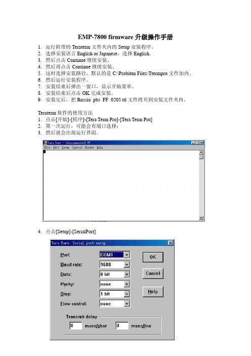
Teraterm软件的使用方法1.点击[开始]-[程序]-[Tera Term Pro]-[Tera Term Pro]2.第一次运行,可能会有端口选择:3.然后就会出现运行界面。
4.点击[Setup]-[SerialPort]5.点击[Setup]-[Terminal]设定完后点击OK返回。
6. 运行程序点击[Control]-[Marco]选择文件:此处选择Russia_pbs_FF_0205.ttl。
然后自动运行。
注意事项:1.运行Firmware升级程序时子连接电源线和9针反转串口线(2和3反转,4和6反转),不要连接其它任何数据线。
2.完成一次升级后,最好关毕所有升级程序的窗口。
在给下一台升级Firmware时,需要重新打开升级程序主窗口。
3.升级需要在投影机投影蓝屏状态以后开始。
4.开始升级打开主窗口后,要按回车键两次,可以看到按下回车键后会出现冒号,以监测PC与投影机间的通讯是否正常。
5.如果通讯没问题,选者升级程序,开始升级。
6.升级结束后检测升级代码是否正确。
按照键入debug 470500,然后会自动出现%,然后依次键入rermaf 32b 03,然后点击回车键,就会自动出现FF FF FF,以下命令依此类推。
最后键入!退出debug命令,然后关闭投影机。
Solaris 8 维护更新 7 安装指南说明书
Solaris8维护更新7安装指南Sun Microsystems,Inc.4150Network CircleSanta Clara,CA95054U.S.A.部件号码816-3485-102002年2月Copyright2002Sun Microsystems,Inc.901San Antonio Road,Palo Alto,California94303-4900U.S.A.版权所有。
本产品或文档受版权保护,其使用、复制、发行和反编译均受许可证限制。
未经Sun及其授权者事先的书面许可,不得以任何形式、任何手段复制本产品及其文档的任何部分。
包括字体技术在内的第三方软件受Sun供应商的版权保护和许可证限制。
本产品的某些部分可能是从Berkeley BSD系统衍生出来的,并获得了加利福尼亚大学的许可。
UNIX是通过X/Open Company,Ltd.在美国和其他国家独家获准注册的商标。
Sun、Sun Microsystems、Sun标志、、AnswerBook、AnswerBook2、Solaris8维护更新、SunOS、JumpStart,和Solaris是Sun Microsystems,Inc.在美国和其他国家的商标、注册商标或服务标记。
所有SPARC商标均按许可证使用,它们是SPARC International, Inc.在美国和其他国家的商标或注册商标。
带有SPARC商标的产品均以Sun Microsystems,Inc.开发的体系结构为基础。
The OPEN LOOK and Sun TM图形用户界面是Sun Microsystems,Inc.为其用户和许可证持有者开发的。
Sun对Xerox为计算机行业研究和开发可视图形用户界面概念所做的开拓性工作表示感谢。
Sun已从Xerox获得了对Xerox图形用户界面的非独占性许可证,该许可证还适用于执行OPEN LOOK GUI和在其他方面遵守Sun书面许可协议的Sun许可证持有者。
A798t软件升级说明书精品文档7页
A798t软件升级说明书目录A798t软件升级说明书 (1)目录 (1)第一章升级前软硬件准备 (3)1.1 软件准备工作 (3)1.1.1 升级工具软件 (3)1.1.2 升级数据线驱动程序 (3)1.2 硬件准备工作 (3)1.2.1 升级数据线 (3)第二章软件升级设备连接示例 (4)第三章驱动安装 (5)第四章软件升级 (8)第五章升级完毕开机检验 (11)第一章升级前软硬件准备1.1 软件准备工作1.1.1 升级工具软件1.1.2 升级数据线驱动程序1.2 硬件准备工作1.2.1 升级数据线第二章软件升级设备连接示例数据线I/O接数据线的USB端GB 5pin-USB数据第三章驱动安装注意事项:1、用于升级的电脑需要运行工具包里的wmp11-windowsxp-x86-zh-cn.exe把WindowsMedia player升级到版本11以上。
2、若电脑已经安装该驱动,则直接进入升级部分。
3、软件包里的文件都需要解压。
驱动安装操作步骤:1、手机关机,用升级线连接手机和电脑,当PC未安装过驱动时会弹出新硬件向导,选择“从列表或指定位置安装(高级)”并点击“下一步”:2、点击“浏览”,选择“SP_Drivers_v1.3”驱动,(路径/Lenovo A798t_S114_1208192ad23e\A798T升级工具__20120515 (v3.1216.02)),选择后并点击“下一步”电脑开始自动安装:3、自动安装界面:4、点击“完成”即完成驱动安装,完成后手机与数据线连接断开:四、软件升级1、双击运行“Flash_tool.exe”软件工具,如图所示:(路径/Lenovo A798t_S114_120819 2ad23e\A798T升级工具__20120515(v3.1216.02) 初始界面如下:2、点击“Scatter-loading”按钮:3、选择“MT6577_Android_scatter_emmc.txt”文件,(路径/Lenovo A798t_S114_120819 2ad23e\target_bin\target_bin)并点击“打开”:4、如图,分别将“Options”菜单下的“USB Mode”“DA Download ALL”与“DA DL ALL With Check Sum”三个选项勾选:5、点击“”,手机装上电池,关机状态,连接至PC端,即开始自动下载:6、若进度条上显示红色的100%,并弹出新硬件向导,需再次安装另一驱动。
Leviton OmniTouch 7 固件和核心升级指南说明书
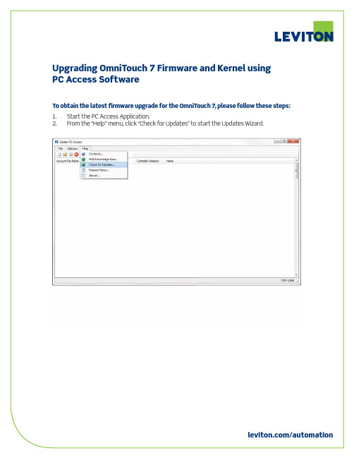
18. After the OmniTouch 7 restarts, press the Settings icon on the bottom-right of the OmniTouch 7 menu bar.
19. Press and hold the Settings icon for 3 seconds. 20. The firmware version is displayed in the title bar. Verify that the Kernel Version is 1.1
/automation
5. Next, the Updates Wizard will prompt you if controller firmware updates are available. 6. Click “Next”.
/automation
7. Next, the Update Wizard will prompt you if OmniTouch 7 firmware upgrades are available. 8. If OmniTouch 7 firmware upgrades are available, click “Download” to download
1.1 or higher and click “Open”. Note: The OmniTouch touchscreen must be running firmware version 1.12 or higher before the Kernel upgrade file (e.g. OmniTouch_7_Kernel_Ver_1_1_99A00-1_2.ot7f) can be applied.
Glunz-Jensen G NUCII 软件升级说明书
the upper side panel (top figure),
•
or 2
• through the upper side panel (bottom figure).
ppp = processor platform (e.g. hdx)
sss = software version (e.g. 20100316)
51436 ...pdf Quick Intro, Control Panel
(English)
51464 ...pdf Control Panel, Service Guide
51412 ...pdf Control Panel, Users Guide (English)
Manuals reflecting the software update are available on the software download site. User manuals are available in English, German, French, Spanish and Chinese. Print manuals as colour prints.
This upgrade will take approx. 1/4 hour.
"
1 Insert the memory stick into a USB port on a PC. Please visit /support for download of software.
$
Visit /support. Enter the software download site. 2 If it is not clear which software to download, a table showing processor types will
[VIP专享]华为设备软件升级功能实现说明
![[VIP专享]华为设备软件升级功能实现说明](https://img.taocdn.com/s3/m/f2ef5d1083d049649a665896.png)
0% 0%
0
0
GigabitEthernet1/0/0
*down down
0% 0%
0
0
GigabitEthernet1/0/1
*down down
0% 0%
0
0
GigabitEthernet1/0/2
*down down
0% 0%
0
0
GigabitEthernet1/0/3
*down down
0% 0%
*down: administratively down
^down: standby
(l): loopback
(s): spoofing
(b): BFD down
(d): Dampening Suppressed
InUti/OutUti: input utility/output utility
Interface
up
--
0.06% 0.05%
0
up
--
0.05% 0.03%
0
up
--
0.03% 0.01%
0
up
--
0.01% 0.01%
Hale Waihona Puke 0up--
0.05% 0.09%
0
up
--
0.01% 0.01%
2
up
--
0.01% 0.01%
0
up
--
0% 0.01%
0
up
--
0% 0.01%
0
up
--
1 CE 设备软件升级
1.1
升级前设备状态检查备份与 ping 测试.
状态检查与备份
- 1、下载文档前请自行甄别文档内容的完整性,平台不提供额外的编辑、内容补充、找答案等附加服务。
- 2、"仅部分预览"的文档,不可在线预览部分如存在完整性等问题,可反馈申请退款(可完整预览的文档不适用该条件!)。
- 3、如文档侵犯您的权益,请联系客服反馈,我们会尽快为您处理(人工客服工作时间:9:00-18:30)。
8A07软件升级说明
2012.10.25
声明:请尽量使用非串口升级方式升级主程序和UBOOT程序8A07系列机器有两部分程序可以进行后续升级:主程序和UBOOT程序,主程序对应nand flash(主程序芯片,位号U172)中程序,UBOOT程序对应spi flash(引导程序芯片,位号U158)中程序。
可以有四种方式对nand flash(主程序芯片,位号U172)进行升级。
方式一:本地U盘(或SD卡)手动升级。
将升级压缩包存入U盘(或SD卡)的根目录,开机后插入存储有主程序的U盘(或SD卡),进入“高级设置”→“本地升级”,然后根据菜单提示,选择要升级的主程序进行升级。
用这种方式进行升级时, OSD会提示系统自动关机,此时不能对电视进行操作,请等待电视自动重启,重启后才进入真正的升级阶段,此时OSD显示ANDROID机器人和升级进度。
升级完成后会自动对电视机重启。
方式二:在线升级。
首先保证电视机网络畅通。
开机后插入外接存储设备(U盘或SD卡,需有足够放置升级文件压缩包的存储空间,默认下载位置为SD卡或USB的根目录),进入“高级设置”→“在线升级”,会启动在线升级检测流程。
系统会自动检测当前网络后台挂载的系统软件程序版本信息,以及任务管理器中升级文件压缩包的下载情况,给予提示,执行下载任务。
下载任务完成后,会弹出提示信息,可以通过再次点击在线升级,或点击任务管理器中系统软件升级包对应的安装按钮,启动升级对话框。
点击确定按钮后将会使用下载的升级文件压缩包进行系统升级(如果放弃升级请点击取消按钮)。
方式三:使用USBBOOT开关自动升级方式。
详见下文第一部分说明。
方式四:使用串口命令方式升级。
详见下文第二部分说明。
可以有两种方式对spi flash(引导程序芯片,位号U158)进行升级。
方式一:使用USBBOOT开关自动升级方式
详见下文第一部分说明
方式二:使用串口命令方式升级
详见下文第二部分说明
第一部分:使用USBBOOT开关升级主程序和UBOOT程序主程序和UBOOT程序都可以采用U盘自动升级的方式进行。
首先要保证U盘(最好是4G以下的u盘,并且不要分区,否则有可能识别不到)根目录下存有aml_autoscript文件,如果需要升级主程序,就将update.zip文件以及factory_update_param.aml文件存入U盘根目录。
如果需要升级UBOOT程序,就将spim2c.bin文件存入U盘根目录,请注意,如果U盘根目录下同时存有spim2c.bin 和update.zip,则会先升级spim2c.bin,然后再升级update.zip,也就是说,两个程序一次性完成升级,因此,在插入U盘前请先确定需要升级的文件是哪个。
升级方法为:
1. 将所有需要升级的程序拷贝到U盘根目录下。
2. 打开USBBOOT开关。
方法有两个:
方法一:开机,音量减到零,按住键控板上的音量减键的同时按遥控器上的屏显键(或返回键)进入工厂模式。
进入“高级设置”选项(密码为123456),将“USBBOOT”改为“开”。
或者使用工厂模式菜单首页的“复位初始化”功能,此功能也包含了打开USBBOOT开关的操作(此方式仅适用于生产线返工的情况)。
方法二:使用串口打开USBBOOT开关。
首先进入UBOOT命令行状态(如何进入该状态请参见第三部分“如何使用串口”的第三部分),然后顺序输入下面两个命令:set usbboot 1
save
每一行代表一个命令,每个命令都以回车结束,命令可以通过复制的方式输入。
输入这两个命令后,USBBOOT开关就打开了,等同于在工厂模式菜单中修改“USBBOOT”选项。
3. 交流关机,插入u盘(请插在最下方的USB端口),拔掉其他usb接口上的usb
设备,交流开机。
4. 如果是升级UBOOT程序,开机后会比平时黑屏时间略长一点。
如果是升级主程序,
则会在电视界面上出现android机器人,其下方有升级进度,主程序升级完成后会自动重启。
升级后第一次重启的阶段由于会进行数据拷贝因此开机速度会比平时长3-5分钟,请勿在这个阶段关机,以避免由于数据拷贝出错导致的系统异常。
5. 电视开机后,重新进入工厂菜单,检查所升级软件的版本,如果是升级主程序,
请看工厂菜单第一行“CPU:”,如果升级UBOOT程序,请看看工厂菜单第三行“引导程序版本”,进行版本确认。
然后再进入高级设置查看“USBBOOT”选项,升级成功后,“USBBOOT”选项应该为“关”。
请务必核对这两项,如果不正确则表示没有升级成功,请重新操作步骤1-5.
请注意如果曾经进行过将USBBOOT选项设为“开”的操作,在将电视交给客户之前一定要保证USBBOOT选项为“关”,否则在用户手中将产生无法预料的后果。
如果没有升级成功,请先确认USBBOOT项是否为开,并检查是否插在最下方的端口上(只有这个端口可以进行自动升级),然后再确认u盘是否符合要求并且根目录下存在需要的文件(文件名必须是aml_autoscript、update.zip、factory_update_param.aml和spim2c.bin)。
或者使用其他u盘再试一下。
第二部分:使用串口命令方式升级
首先进入UBOOT命令行状态(如何进入该状态请参见第三部分“如何使用串口”的第三点)。
主程序升级步骤如下:
将插有update.zip文件(请注意升级文件名必须为update.zip,如果拿到的程序名不同,请自行修改为update.zip)和factory_update_param.aml文件的U盘插到最下方USB端口中,并输入命令“run recoverynand”(本命令不包含引号在内),然后回车,就可以进行主程序的升级了。
正常的升级界面是android机器小人下方有进度条。
升级完成后系统会自动重启电视。
注:1.有时系统会提示“请在U盘根目录下插入update.zip,并按确认键升级”,
或者其他错误提示,比如提示按左键或者之类的提示,而实际上U盘里已经存有update.zip文件,这种情况往往是由于U盘格式问题,可以将U盘格式化一下,再拷贝进入update.zip重新进行上述1、2步骤。
2.最好使用4G以下U盘,并且U盘内不要分区,否则有可能识别不到文件。
3.如果run recoverynand命令升级不成功,可以尝试run recoveryspi命令。
UBOOT升级程序如下:
UBOOT程序是系统启动程序,除非有明确收到需要升级UBOOT的通知,否则不要对此程序进行升级。
1.将spim2c.bin存入U盘,并插入USB端口;
2.交流开机,迅速敲击回车键直至出现命令符M2_SOCKET#;
3.依次输入如下命令:
usb start
fatload usb 0:1 82000000 spim2c.bin
sf probe 2
sf erase 0 200000
sf write 82000000 0 200000
4.输完最后一个命令后,等到再次出现命令符M2_SOCKET#后,关闭电视电
源后重启。
请注意:输入命令过程中不能断电,因为此时spi flash已经被清空,如果在写入完成之前断电,spi flash将无法执行系统启动的功能,只能换spi flash了。
输入命令后,一定要等到命令符M2_SOCKET#再次出现后才能输入下一条命令,有的命令输入后要等待一段时间才能完成,请耐心等待。
第三部分:如何使用串口
一、升级线准备
可以使用与8A01串口升级同样的线和小电路板,连接线一端插在小电路板上CN2_A接口,另一端插在电视的VGA接口。
小电路板上的开关选择UART,如图所示(也可使用其他USB转VGA电路):
二、升级软件准备
1.首先要保证电脑上安装了USB转串口驱动CH341SER.EXE(或其他USB转VGA串口
电路的驱动程序);
2.安装SecureCRT(串口通信工具),将压缩包里解压出来的SecureCRT目录拷贝至
自己的目录即可,里面的SecureCRT.exe可以直接使用;
3.配置SecureCRT。
首先双击SecureCRT.exe,为新启动的会话起一个名字,然后进
入下图界面(以后在进入SecureCRT.exe可以在“选项”中选择“会话选项”,也
能进入这个界面):
请根据上图配置串口,右侧画红圈部分三个勾都要去掉,全部不选,波特率选择115200。
关于端口,请在插好USB转串口线后,在“我的电脑”图标上按右键,选择“属性”,再选择“硬件”中的“设备管理器”,查询里面的“端口”即可知道本机使用的是哪个端口,请根据自己的电脑配置情况选择端口号(如果是非XP系统,请自行设法找到“设备管理器”)。
如下图所示。
请注意,如果每次使用同一个USB口,那么端口号应该不会变,如果插在了不同的USB口上,端口号需要重新配置。
如果出现无法连接的情况,往往是由于端口号不正确造成的。
只要不换端口,会话选项只需第一次配置即可,以后每次都会沿用上次配置。
配置好以后会看到光标闪烁。
三、进入UBOOT命令行状态
将串口和电视连接好,然后电视交流开机后迅速敲击回车键,直至secureCRT 界面出现了“M2_SOCKET#”字样,就进入了UBOOT命令行状态,此时可以对电视输入一些命令,进行文件升级。
如下图所示:。