哈工大毕业设计外文翻译模板
外文翻译模版
大连民族学院
本科毕业设计外文翻译
学院:
专业(班级):
学生姓名:
指导教师:
2012年月日
1
每名学生在毕业设计(论文)期间,应完成译文不少于3千汉字的外文资料翻译。
译文内容必须与毕业设计(论文)内容有关,原则上是近五年出版的期刊(不可翻译有中文译文的书籍或期刊)。
1.1译文正文格式
译文正文格式同毕业设计(论文)正文格式要求。
1.2 译文页眉页脚的编排
页脚要求同毕业论文页脚要求,一律用阿拉伯数字连续编页码。
页码应由正文首页开始,作为第1页。
封面不编入页码。
页码必须标注在每页页脚底部居中位置,宋体,小五。
无页眉。
1.3标题格式
各级标题格式同毕业论文中相关要求。
2 打印和装订说明
2.1 封皮
按照首页格式制作封面。
2.2 正文
单面打印。
2.3装订规范要求
装订时原文在前,译文在后,左侧装订。
译文必须于毕业设计(论文)中期检查前完成,交指导教师批改。
–1–。
毕业设计中英文翻译【范本模板】
英文The road (highway)The road is one kind of linear construction used for travel。
It is made of the roadbed,the road surface, the bridge, the culvert and the tunnel. In addition, it also has the crossing of lines, the protective project and the traffic engineering and the route facility。
The roadbed is the base of road surface, road shoulder,side slope, side ditch foundations. It is stone material structure, which is designed according to route's plane position .The roadbed, as the base of travel, must guarantee that it has the enough intensity and the stability that can prevent the water and other natural disaster from corroding.The road surface is the surface of road. It is single or complex structure built with mixture。
The road surface require being smooth,having enough intensity,good stability and anti—slippery function. The quality of road surface directly affects the safe, comfort and the traffic。
本科毕业论文英文翻译格式模板
毕业论文(设计)
英文翻译
姓名
学号
所在学院
专业班级 2007级信科2班
指导教师
日期 2011年3月30 日
英文原文(三号宋体加粗,段前0.5行,段后0.5行,居中)
Introduce a kind of dormancy of using- restore to the throne in theoperation way and improve the anti-interference ability method of the one-chip computer;Analyse its scope of application, provide and use the circuit concretly; Combine the instance, analyse the characteristic of the hardware and software design under these kind of operation way. (Times new Roman小四,1.25倍行,段前0行,段后0行,两端对齐)
中文翻译(三号宋体加粗,段前0.5行,段后0.5行,居中)
介绍一种用休眠-复位运行方式提高单片机抗干扰能力的方法;分析其适用范围,给出具体应用电路;结合实例,分析这种运行方式下硬件和软件设计的特点。
(小四,1.25倍行,段前0行,段后0行,两端对齐)。
毕业论文外文翻译格式【范本模板】
因为学校对毕业论文中的外文翻译并无规定,为统一起见,特做以下要求:1、每篇字数为1500字左右,共两篇;2、每篇由两部分组成:译文+原文.3 附件中是一篇范本,具体字号、字体已标注。
外文翻译(包含原文)(宋体四号加粗)外文翻译一(宋体四号加粗)作者:(宋体小四号加粗)Kim Mee Hyun Director, Policy Research & Development Team,Korean Film Council(小四号)出处:(宋体小四号加粗)Korean Cinema from Origins to Renaissance(P358~P340) 韩国电影的发展及前景(标题:宋体四号加粗)1996~现在数量上的增长(正文:宋体小四)在过去的十年间,韩国电影经历了难以置信的增长。
上个世纪60年代,韩国电影迅速崛起,然而很快便陷入停滞状态,直到90年代以后,韩国电影又重新进入繁盛时期。
在这个时期,韩国电影在数量上并没有大幅的增长,但多部电影的观影人数达到了上千万人次。
1996年,韩国本土电影的市场占有量只有23.1%。
但是到了1998年,市场占有量增长到35。
8%,到2001年更是达到了50%。
虽然从1996年开始,韩国电影一直处在不断上升的过程中,但是直到1999年姜帝圭导演的《生死谍变》的成功才诞生了韩国电影的又一个高峰。
虽然《生死谍变》创造了韩国电影史上的最高电影票房纪录,但是1999年以后最高票房纪录几乎每年都会被刷新。
当人们都在津津乐道所谓的“韩国大片”时,2000年朴赞郁导演的《共同警备区JSA》和2001年郭暻泽导演的《朋友》均成功刷新了韩国电影最高票房纪录.2003年康佑硕导演的《实尾岛》和2004年姜帝圭导演的又一部力作《太极旗飘扬》开创了观影人数上千万人次的时代。
姜帝圭和康佑硕导演在韩国电影票房史上扮演了十分重要的角色。
从1993年的《特警冤家》到2003年的《实尾岛》,康佑硕导演了多部成功的电影。
毕业论文外文翻译格式【范本模板】
盐城师范学院毕业论文(设计)外文资料翻译学院:(四号楷体_GB2312下同)专业班级:学生姓名:学号:指导教师:外文出处:(外文)(Times New Roman四号) 附件: 1.外文资料翻译译文; 2.外文原文1.外文资料翻译译文译文文章标题×××××××××正文×××××××××××××××××××××××××××××××××××××××××××××××××××××××××××××××××………….*注:(本注释不是外文翻译的部分,只是本式样的说明解释)1. 译文文章标题为三号黑体居中,缩放、间距、位置标准,无首行缩进,无左右缩进,且前空(四号)两行,段前、段后各0.5行间距,行间距为1。
25倍多倍行距;2. 正文中标题为小四号,中文用黑体,英文用Times New Roman体,缩放、间距、位置标准,无左右缩进,无首行缩进,无悬挂式缩进,段前、段后0。
5行间距,行间距为1.25倍多倍行距;3。
正文在文章标题下空一行,为小四号,中文用宋体,英文用Times New Roman体,缩放、间距、位置标准,无左右缩进,首行缩进2字符(两个汉字),无悬挂式缩进,段前、段后间距无,行间距为1。
毕业设计外文文献翻译范文
毕业设计外文文献翻译专业学生姓名班级学号指导教师优集学院外文资料名称:Knowledge-Based Engineeri--ng Design Methodology外文资料出处:Int.J.Engng Ed.Vol.16.No.1附件: 1.外文资料翻译译文2.外文原文基于知识工程(KBE)设计方法D. E. CALKINS1.背景复杂系统的发展需要很多工程和管理方面的知识、决策,它要满足很多竞争性的要求。
设计被认为是决定产品最终形态、成本、可靠性、市场接受程度的首要因素。
高级别的工程设计和分析过程(概念设计阶段)特别重要,因为大多数的生命周期成本和整体系统的质量都在这个阶段。
产品成本的压缩最可能发生在产品设计的最初阶段。
整个生命周期阶段大约百分之七十的成本花费在概念设计阶段结束时,缩短设计周期的关键是缩短概念设计阶段,这样同时也减少了工程的重新设计工作量。
工程权衡过程中采用良好的估计和非正式的启发进行概念设计。
传统CAD工具对概念设计阶段的支持非常有限。
有必要,进行涉及多个学科的交流合作来快速进行设计分析(包括性能,成本,可靠性等)。
最后,必须能够管理大量的特定领域的知识。
解决方案是在概念设计阶段包含进更过资源,通过消除重新设计来缩短整个产品的时间。
所有这些因素都主张采取综合设计工具和环境,以在早期的综合设计阶段提供帮助。
这种集成设计工具能够使由不同学科的工程师、设计者在面对复杂的需求和约束时能够对设计意图达成共识。
那个设计工具可以让设计团队研究在更高级别上的更多配置细节。
问题就是架构一个设计工具,以满足所有这些要求。
2.虚拟(数字)原型模型现在需要是一种代表产品设计为得到一将允许一产品的早发展和评价的真实事实上原型的过程的方式。
虚拟样机将取代传统的物理样机,并允许设计工程师,研究“假设”的情况,同时反复更新他们的设计。
真正的虚拟原型,不仅代表形状和形式,即几何形状,它也代表如重量,材料,性能和制造工艺的非几何属性。
毕业论文外文翻译模版

一、摘要
本文主要介绍了毕业论文外文翻译模版,该模版包括了论文的标题、作者信息、摘要、关键词、引言、正文、结论等部分的翻译模板,可供毕业论文写作时参考使用。
二、标题
毕业论文外文翻译模版
三、作者信息
作者:[姓名]
学号:[学号]
指导老师:[指导老师姓名]
四、摘要
本文介绍了毕业论文外文翻译模版的具体内容和使用方法,帮助毕业论文作者完成外文翻译工作,提高论文质量和水平。详细内容包括论文标题、作者信息、摘要、关键词、引言、正文、结论等部分的翻译模板。
6. 正文的翻译模版:
正文内容丰富多样,翻译时需根据具体内容进,无需额外模版。
八、结论
毕业论文外文翻译模版的使用对于毕业论文写作具有重要意义,能够帮助作者完成外文翻译工作,提高论文的质量和水平。希望本文提供的翻译模版能够对广大学子在论文写作过程中有所帮助,更好地完成毕业论文的撰写工作。
五、关键词
毕业论文、外文翻译、模版、翻译模板、论文写作
六、引言
毕业论文外文翻译是毕业论文写作过程中的一项重要工作,对于提高论文的学术水平和国际影响力具有重要意义。本文提供了一套完整的翻译模版,可供广大学子参考使用,希望能够对大家的论文写作工作有所帮助。
七、正文
1. 论文标题的翻译模版:
中文标题:[中文标题]
英文标题:[英文标题]
2. 作者信息的翻译模版:
作者姓名:[姓名]
作者学号:[学号]
作者专业:[专业]
3. 摘要的翻译模版:
中文摘要:[中文摘要内容]
英文摘要:[英文摘要内容]
4. 关键词的翻译模版:
中文关键词:[中文关键词]
英文关键词:[英文关键词]
毕业设计外文翻译样本
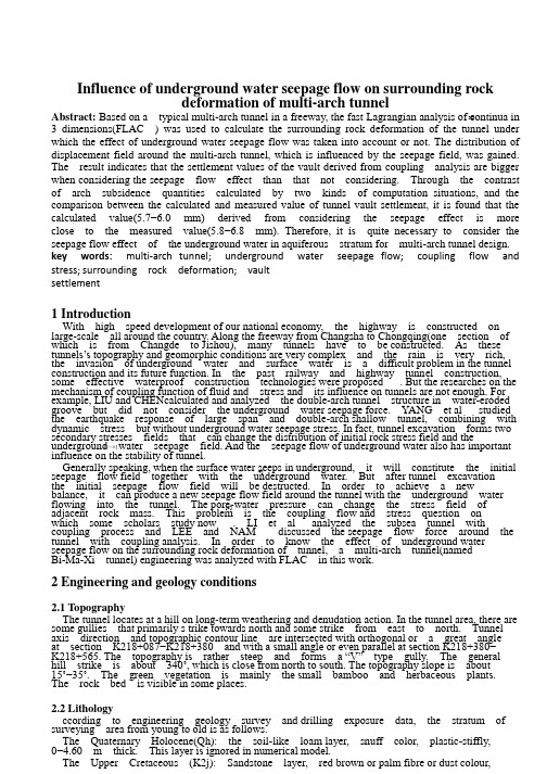
Influence of underground water seepage flow on surrounding rockdeformation of multi-arch tunnelAbstract: Based on a typical multi-arch tunnel in a freeway, the fast Lagrangian analysis of continua in3 dimensions(FLAC ) was used to calculate the surrounding rock deformation of the tunnel under which the effect of underground water seepage flow was taken into account or not. The distribution of displacement field around the multi-arch tunnel, which is influenced by the seepage field, was gained. The result indicates that the settlement values of the vault derived from coupling analysis are bigger when considering the seepage flow effect than that not considering. Through the contrast of arch subsidence quantities calculated by two kinds of computation situations, and the comparison between the calculated and measured value of tunnel vault settlement, it is found that the calculated value(5.7−6.0 mm) derived from considering the seepage effect is more close to the measured value(5.8−6.8 mm). Therefore, it is quite necessary to consider the seepage flow effect of the underground water in aquiferous stratum for multi-arch tunnel design. key words: multi-arch tunnel; underground water seepage flow; coupling flow and stress; surrounding rock deformation; vault settlement1 IntroductionWith high speed development of our national economy, the highway is constructed on large-scale all around the country. Along the freeway from Changsha to Chongqing(one section of which is from Changde to Jishou), many tunnels have to be constructed. As these tunnels’s topography and geomorphic conditions are very complex and the rain is very rich, the invasion of underground water and surface water is a difficult problem in the tunnel construction and its future function. In the past railway and highway tunnel construction, some effective waterproof construction technologies were proposed . But the researches on the mechanism of coupling function of fluid and stress and its influence on tunnels are not enough. For example, LIU and CHENcalculated and analyzed the double-arch tunnel structure in water-eroded groove but did not consider the underground water seepage force. YANG et al studied the earthquake response of large span and double-arch shallow tunnel, combining with dynamic stress but without underground water seepage stress. In fact, tunnel excavation forms two secondary stresses fields that can change the distribution of initial rock stress field and theunderground water seepage field. And the seepage flow of underground water also has importantinfluence on the stability of tunnel.Generally speaking, when the surface water seeps in underground, it will constitute the initial seepage flow field together with the underground water. But after tunnel excavation the initial seepage flow field will be destructed. In order to achieve a newbalance, it can produce a new seepage flow field around the tunnel with the underground water flowing into the tunnel. The pore-water pressure can change the stress field of adjacent rock mass. This problem is the coupling flow and stress question on which some scholars study now . LI et al analyzed the subsea tunnel withcoupling process and LEE and NAM discussed the seepage flow force around the tunnel with coupling analysis. In order to know the effect of underground water seepage flow on the surrounding rock deformation of tunnel, a multi-arch tunnel(named Bi-Ma-Xi tunnel) engineering was analyzed with FLAC in this work.2 Engineering and geology conditions2.1 TopographyThe tunnel locates at a hill on long-term weathering and denudation action. In the tunnel area, there are some gullies that primarily s trike towards north and some strike from east to north. Tunnel axis direction and topographic contour line are intersected with orthogonal or a great angle at section K218+087−K218+380 and with a small angle or even parallel at section K218+380− K218+565. The topography is rather steep and forms a “V” type gully. The general hill strike is about 340˚, which is close from north to south. The topography slope is about 15˚−35˚. The green vegetation is mainly the small bamboo and herbaceous plants. The rock bed is visible in some places.2.2 Lithologyccording to engineering geology survey and drilling exposure data, the stratum of3D [1−3] 4][5]surveying area from young to old is as follows.The Quaternary Holocene(Qh): the soil-like loam layer, snuff color, plastic-stiffly,0−4.60 m thick. This layer is ignored in numerical model.The Upper Cretaceous (K2j): Sandstone layer, red brown or palm fibre or dust colour,fine-grained structure. The calcareous cemented rock layer is mixed with mud cemented rock layer and the former is the main part and it is thin and medium thickness structural layer. The horizontal bedding layer develops and the dip angle is small. According to weathered degree the stratum can be divided into three layers from the top down: intensely, weakly and tinily weathered layer. The sketch map of geology section is shown in Fig.1.Fig.1 Sketch of geological profile for tunnel2.3 Geology constitutionIn tunnel area there is no large fracture structure and nor any new tectogenesis. The geology constitution is a monoclinal structure. The rock dip direction of general occurrence is 95˚−115˚. The dip angle distribution ranges from 8˚ to15˚. Three sets of joint crack develop: 1) dip direction 148˚, dip angle 89˚;2) dip direction 350˚, dip angle 56˚; 3) dip direction 225˚, dip angle 77˚. The joint cracks mostly twist with pressure and crack faces are almost close. Minorities of the crack faces are patulous and the distance between two cracks often varies from 5 to 20 cm. The connectivity is fairly good.3 Construction of 3D numerical model3.1 model of numerical calculationThis tunnel is a freeway multi-arch tunnel, of which the left one and right one are general parallel. The two tunnels are about symmetrical by the middle arch wall. The average thickness of middle wall is 2.1 m. The key dimensions of tunnel section are shown in Fig.2.Fig.2 Sketch of multi-tunnel cross section (unit: cm)When modeling the tunnel, the direction along the tunnel is y-axis and in horizontal plane the perpendicularity of tunnel direction is x-axis and plumb upward is z-axis. The influence of tunnel excavation is considered. The radius of influence range is above 3 times of one tunnel span. So in width direction, 50 m extends respectively outside the left and right tunnel, plus the span itself, width direction calculation range is 125 m. Downwards from the original point is 3 times of the height of the tunnel, which equals 45 m and upward is till the earth’s surface (does not consider the clay layer, calculating depth range includes intensely, weakly, tinily weathered red sandstone from above to below respectively). The buried depth of the tunnel is about 25 m. Plus the 10 m of its height, in z-axis the depth is 80 m. Along the tunnel direction an unit length is considered because tunnel excavation can be considered asa plane-strain problem. The size of the 3D numerical model is 125 m×80 m×1 m. The 3D numerical model and its coordinate axis location are shown in Fig.3.Fig.3 3D numerical model of tunnel in FLACThe displacement boundary conditions are adopted in numerical model. Bottom border is constrained with vertical displacement and upper border is free border. Both left and right border are restrained with horizontal displacement. The same boundary conditions are applied in both the front and back borders in y-axis.3.2 Calculation parametersThe mechanics parameters in numerical analysis are provided by geotechnical engineering investigation data and combined with the national criterion need and parameters discount request in numerical simulation. The mechanics parameters of the surrounding rock and the C25 concrete middle arch wall are listed in Table 1. The surrounding rock and the concrete intensity criteria adopted is the elastic-plastic criterion of Mohr-Coulomb. Table 2 shows the surrounding rock relevant seepage flow parameters when coupling problem is considered in numerical simulation. Table 3 lists the parameters of shot concrete(primary lining) and anchor support structure of the multi-arch tunnel. In this calculation process, the parameters of Grade IV surrounding rock supporting system are adopted. And only the affection of the anchor and shotconcrete is considered. The effect of secondary lining is not considered in numerical simulation.4 Discussion on calculation results4.1 Surrounding rock deformation characteristics without underground water seepage flowBased on the established numerical model, the process in which the underground water seepage flow function was not considered was carried on by FLAC . Fig.4 shows the vertical displacement contour-line map in this instance after multi-arch tunnel excavation. From Fig.4 it can be obviously seen that nearby the tunnel excavation region the rock deformation is relatively serious. The vault rock displacement is negative, indicating that the displacement direction is vertical downwards and subsidence occurs. But around the tunnel bottom the surrounding rock displacement is positive, indicating that the direction is vertical upwards and bulging phenomenon occurs.In the process of numerical calculation, the left and right tunnels were simulated simultaneously, namely they were excavated in the identical section plane simultaneously, that is to say, the influence of the construction order is not considered. In the computation process ofFLAC , some interesting grid points were selected to monitor their vertical displacement. The monitored grid points’ number and corresponding coordinate position are listed in Table 4.Fig.5 shows the time process curves of z-displacement (absolute value) of the monitored grid points around left tunnel vault. From Fig.5 it can be seen that the vertical displacement value(or called settlement value) of tunnel vault surrounding rock has relationship with its own position. The clos er the grid point’s position away from the tunnel excavation region, the larger the settlement value. For example, on the middle upper grid point (41 ) of left tunnel, its final calculation settlement value is 3.7 mm, and another grid poi nts’ values are getting smaller with the distance becoming longer.Fig.5 Time process curves of z-displacement of monitored grid points around le ft tunnel vault4.2 Surrounding rock deformation characteristics with underground water seepage flowThe influencing factors of surrounding rock deformation after tunnel excavation in Refs.[10−13], mainly concentrating on the grade of surrounding rock, excavating and supporting method, the neighbor construction load and the construction working procedure. Generally it almost does not consider the influence of underground water seepage flow. But in fact, the underground water existence has important influence on the surrounding rock deformation. For instance, in the excavation and tunnel engineering, the underground water seepage flow can cause quite big displacement of the soil or rock mass and even threaten the safety of engineering . In this study, some quantitative researches on the influence of surrounding rock deformation were carried out by underground water seepage flow.The stratum is fully saturated with water before tunnel is excavated. The seepage flow boundary condition includes that thepore-water pressure of the top surface is limited to zero and the two sides as well as the base boundary are water-proof boundaries . Before tunnel excavation the pore pressure of the stratum is hydro-static pressure. After tunnel excavation, around the tunnel excavation boundary is simulated by a free water seepage flow boundary where the adjacent underground water infiltrates into the excavated area. And the seepage flow field of surrounding rock has been changed with the excavation being carried on. Then the coupling analysis was executed by FLAC .Fig.6 shows the vertical displacement contour-line map after multi-arch tunnel excavation when considering the underground water seepage flow function. Obviously it can be seen that in coupling analysis the arch subsidence quantity is larger than that of not considering seepage function andthe affected region is also wider than that of the former as shown in Fig.4.Fig.6 z-displacement contour-line map of surrounding rock when considering underground water seepage flow function (unit: mm)coupling analysis, as the change of pore pressure in surrounding rock, the effective stress will be changed and it will cause the rock porosity ratio to reduce, leading to a larger arch subsidence quantity compared with that of not considering the seepage flow effect. But the vertical displacements at the bottom of the tunnel are not changed a lot. Fig.7 shows the calculated vertical displacement value for both vault’s middle position (grid point 41 and gridpoint 52 ). It can be seen that the subsidence quantity gradually increases with computation development, after finally tends to its new balance, both vault’s vertical displacement quantities finally stabilize at about 5.7 mm and the two time process curves are basically consistent.Fig.7 Curves of both vault’s node displacement vs calculation stepsFig.8 shows the time process curves of z -displacement(absolute value) of the monitored grid points around the left tunnel vault when taking the underground water seepage flow intoconsideration. Contrasting with Fig.5 it is obviously seen that the settlement value of 41 grid point is increased and reaches 5.7 mm. And to the other monitored grid points, their subsidence quantities also basically tend to 5.0 mm. The calculation subsidence quantities do not change when their relative positions changes.Fig.8 Time process curves of vault settlement when taking underground water seepage f low into consideration4.3 Comparison of deformation measurement results of surrounding rock In the process of excavating, the Bi Ma-Xi tunnel, the inspecting and consulting company of the fourth investigation and design institute of Chinese Railways Ministry monitored the surrounding rock deformation. Fig.9 shows the monitored vault settlement curves at sections K218+280 and K218+310.#Fig.9 Curves of measured value of vault settlement in process of left tunnel excavationComparing Fig.9 with Fig.5 and Fig.8, the maximal vault settlement calculation value is 3.7 mm when without considering underground water seepage flow, and when taking it into consideration the maximal calculation value is equal to 5.7 mm. And the practical monitored results reach 6.5 mm and tend to be stable after 2 months when the tunnel is excavated. The case fits very well with the coupling analysis result. The vault settlement measurement values in this multi-arch tunnel are all basically leveled off between 5.8 mm and 6.8 mm.The calculation results of coupling fluid-mechanical analysis are slightly smaller than the measured results. The reason is that the numerical calculation is thought as converged when the maximal unbalanced force in surrounding rock tends to a less value after tunnel excavation. And it does not consider the effect of actual time. The parameters in calculating unavoidably exist difference with the parameter of rock mass in reality. These reasons lead to the difference between the coupling analysis and the engineering measurement. But the results obtained in section 4.1 are less than the measuring results considering it indicates that the numerical analysis without underground water seepage flow cannot meet the need of engineering.5 Conclusions1) When underground water seepage flow function is considered in coupling fluid-mechanical analysis, the calculation vault settlements have finally achieved5.7−6.0 mm with the interaction of undergroundwater seepage flow and stress release in surrounding rock around the tunnel. The coupling calculation results are very close to the vault measurement settlement. It indicates that constructing tunnels in aquiferous stratum the underground water seepage flow effect must be considered in the design phase.2) The settlement of the surrounding rock above the tunnel has close relationship with its own position. The region near the tunnel excavation zone has the biggest rock deformation, so it should promptly complete supporting measures. When not considering the seepage flow function, the farther the region, the smaller the rock deformation; but when considering the seepage flow function, the settlement of the surrounding rock is above the tunnel and then basically tends to stable in shallower tunnel and it has obviously influence on the ground surface subsidence.地下水渗流对双连拱隧道围岩变形的影响摘要:一般来说,对于高速公路双连拱隧道,用FLAC3D计算隧道围岩变形时是没有考虑到地下水渗流影响的。
- 1、下载文档前请自行甄别文档内容的完整性,平台不提供额外的编辑、内容补充、找答案等附加服务。
- 2、"仅部分预览"的文档,不可在线预览部分如存在完整性等问题,可反馈申请退款(可完整预览的文档不适用该条件!)。
- 3、如文档侵犯您的权益,请联系客服反馈,我们会尽快为您处理(人工客服工作时间:9:00-18:30)。
本科毕业设计(论文)外文文献翻译文献题目Hover Performance of a Small-Scale Helicopter forFlying on Mars专业飞行器制造工程班号1308302学号**********学生陈水添可用于火星飞行的小型直升机转子悬停性能Robin ShresthaUniversity of Maryland, College Park, Maryland 20742Moble BenedictTexas A&M University, College Station, Texas 77843以及Vikram Hrishikeshavan 和Inderjit Chopra§University of Maryland, College Park, Maryland 20742DOI:10.2514/1.C033621摘要:本研究是为了回应对于评估用于火星探测的小型自动化直升机(总质量小于1 kg)飞行可行性与日俱增的兴趣。
自主旋翼航空器可以理想地适用于这样的应用,因为它具有独特的优点,其中包括在与传统的地面漫游器相比时在恶劣的地形上垂直起飞/着陆的能力以及更大的速度,范围和视野。
火星上的大气条件呈现出独特的设计挑战。
尽管火星的重力只有38%左右地球的重力,火星的平均大气密度是地球大气密度的七十分之一。
因此,转子将以非常低的雷诺数运行,对于小型直升机而言,甚至低于5000。
然而,由于需要更高的尖端速度(由于密度较低),马赫数将显着更高(M> 0.4),并且由于火星上的声速仅为地球声速的大约72%。
桨叶上的低雷诺数,高马赫数流动条件对转子设计施加了严格的限制。
本研究提出的解决方案涉及扩大转子尺寸以在可接受的马赫数和雷诺数条件下产生所需的推力。
实验在一个真空室中评估了200 g火星同轴直升机的全尺寸转子的悬停性能,真空室完全模拟了火星空气密度。
在雷诺数为3300,马赫数为0.34的情况下,基线转子获得的最大品质因数小于0.4。
通过改变空气密度以恒定的马赫数增加雷诺数,雷诺数为35,000,将同一转子的品质因数提高到0.6以上。
随着雷诺数降低到极低值(Re <5000),最大品质因数的桨叶总距角甚至增加到30度。
这项研究的一个重要结论是小型火星无人机在火星持飞行(12 – 13 min)是可行的。
I.引言这里存在一个用于评价用于火星探测的小型旋翼机可行性的巨大兴趣。
本研究与NASA的在火星2020任务中操作一架小型旋翼无人机从火星漫游者起飞的目标一致。
小型的火星旋翼机被设想作为传统表面漫游车的探路者。
一架飞行平台的优势在于:更高的速度、更广的范围以及相比于传统的漫游车更大的视野范围。
火星表面呈现出独一无二的挑战,因为它表面的多样性和崎岖不平,这将限制传统的漫游车到达许多值得高度关注兴趣点的机动性。
例如,让轮式漫游车去探索小火星沟中源头和沿着火星峡谷悬崖面分布的土壤似乎是不可能的。
然而探索这些特征对于了解它们形成和水在火星过去和现在扮演的角色至关重要[1]。
一个飞行器将会拓宽我们的探索能力。
一架星际飞行器将会移除穿过危险的巨石散落地区或击中不可能绕过障碍物的挑战。
一架理想的火星飞行器将是拥有从着陆区垂直起飞,穿过并且在具有高科研兴趣崎岖上方悬停,收集科学数据的能力。
为了这个任务,在过去,不同的飞行平台已经被提出来。
自1960年起,火星探测就被通过三种方式进行:略过,环绕以及着陆/漫游。
然而,在过去的二十年里,已经有很多的研究聚焦于探索新概念飞行器的可行性,这些飞行器将通过高分辨率成像、下放探针或传感器、采集微小样品、作为探路者以及进行高危险性任务等方式来提升火星表面探索的能力。
这些研究关注点在于三种不同的概念:比空气轻的飞行器、固定翼飞行器以及旋翼机。
这些飞行器的采用将取决于任务的类型以及财务预算。
例如,这里已经有很多通过实验和分析研究来设计/构建用于火星环境的比空气轻的概念机(热气球/飞艇)。
这里最大的挑战在于满足对于在火星大气环境中轻型热气球的平衡要求以及承受在展开和膨胀过程中的瞬态负载。
俄罗斯/法国的“火星空气飞行器”项目(1987 - 1995年)首先采取的主要措施之一,其目标是将气球系统(Aerostat)发射火星大气中,并在火星表面上飞行10天,进行原位科学探索[3]。
拟议的空气飞行器将在距离地面4公里的高度漂浮5500立方米圆柱形超压外壳。
但是,这个项目是在取得重大特破之前便在1995年被取消了。
喷气推进实验室的火星气球验证计划(MABV AP)的另一项重大工作,该工作是1997年8月发起,旨在开发和验证火星任务所需的关键技术[4]。
MABV AP的三个主要组成部分是验证空中展开和膨胀,超压热气球设计和开发新的仿真工具。
作为该计划的一部分,从1997年到2002年,制造和测试了一些超压气球。
其次是联合喷气推进实验室(JPL),Wallops飞行设施和近空间公司进行研究成为称为“超级-M”的工作。
2006年,SUPER-M队对火星全尺寸原型气球进行了成功的空中展开和膨胀测试[5]。
这些测试发生在31公里高度的地球平流层,在那里低气压密度与火星表面附近的大气密度相当,主要技术重点是进行空中产开和膨胀过程。
在20世纪70年代后期,随着JPL的资助和指导,发展科学公司(DSI)进行了可能是对火星固定翼飞机可行性的最全面的早期调查[6]。
设计的最终飞机(名为“Astroplane”)的翼展为21米,机翼面积为20平方米,标称质量为300公斤。
采用一个复杂的折叠方案,其中包括六个翼折,三个机身折叠和折叠螺旋桨,以将Astroplane装配到3.8米的类Viking壳中。
自从DSI研究以来,已经有几个美国航空航天局,工业和大学对火星飞行任务的研究。
众所周知的工作是NASA 兰利研究中心的ARES(火星地区范围的火星环境调查)项目,目标是使用专门设计的固定翼飞机来探索火星南部高地[7]。
最终飞机设计的翼展6.25米,估计总重150公斤,范围500公里,耐力1小时。
飞机的大尺寸(翼区面积7平方米)允许它以可操控的空气动力学状态中(马赫数在0.62和0.71之间,雷诺数在100,000和200,000之间)运行。
该飞机的推进系统由双组元推进剂,脉冲控制火箭推进系统与单甲基肼燃料和氮氧化物混合氧化物组成。
这架飞行器的半尺度模型是在2002年建成的,并在103,500英尺的高度进行了成功的自主高空展开和抽出过程,许多其他固定翼飞机任务和概念设计由各个机构提出[6 -9],其中飞行器尺寸范围从2到12米,翼展,总重量从20到200公斤,耐力15分钟至3小时,范围从130到1800公里,巡航速度从110到160米/秒不等。
尽管比空气轻概念在功耗方面是效率最高的,但由于对任何重要的有效载荷及其对风的敏感性都需要较大的气囊尺寸,因此它们并不实用。
他们也缺乏探索有针对性的科学兴趣领域的控制权。
固定翼飞机相对有效;然而,他们以非常高的速度(大于100米/秒)飞行的必要性对其任务能力施加了很多限制,并使它们在第一次飞行之后不可重新覆盖研究区域。
另一方面,旋翼航空器即使是三个系统中功耗最大的一种,但是它具有极高的灵活性,具有悬停/低速飞行能力,非常适用于许多任务。
旋翼航空器具有独特的优势,能够从崎岖的地形起飞和降落,以及悬停和低速飞行,以调查不利地形(比轨道飞行器更接近)。
它还可以将传感器从漫游车精确地传送到任何位置,并将样本从远程站点返回到主漫游车。
使用旋翼飞机作为火星行星探测的空中平台有很多潜在的好处。
然而,火星上的条件提出了非常独特的设计挑战。
火星的重力大约只有地球重力的三分之一,但是火星的大气密度是地球的七十分之一。
火星上的声速也只有地球上的72%。
火星上的超低空气密度要求转子以非常高的旋转速度运行,以产生所需的推力。
结果,叶片将经历独特的低雷诺数(Re)/高马赫数流动条件,这种情况通常不会在任何其他常规飞行器上发生。
低雷诺数,高马赫数流量没有实验数据;因此,空气动力学预测可能不准确。
因此,为这些流动状况生成的转子性能数据库至关重要。
目前的研究集中在一个小型旋翼机(质量〜200克),这可以用来从漫游车上进行巡视任务。
已经有一些实验研究系统地研究了微型飞行器(MA V)尺度转子(直径在6英寸内)的低雷诺数(Re = 30; 000至60,000)[10-13]的空气动力学。
然而,这些转子在非常低的马赫数(M〜0.03)下在地球的大气密度(ρ= 1.225kg / m3)下进行了测试,低雷诺数是由于转子的缩小而导致的。
MA V转子研究的结果支持使用弧形(弧度为6至9%),圆弧平板翼型,锋利的前缘雷诺数小于60,000的桨叶。
Bohorquez在MA V规模转子(Re≈60; 000)上进行的实验表明,具有锋利前缘的细圆弧形锯片(6-9%)桨叶的转子具有优异的性能[13,14]。
使用由Lakshminarayan和Baeder在悬停MA V标尺转子上进行的雷诺兹Navier-Stokes求解器的计算研究表明,具有钝前缘的叶片的性能差的原因是由于层流引起的前部压力阻力较大分离气泡[15]。
Benedict等人的进一步实验测试和系统优化了不同的叶片参数,包括叶片翼型,叶片弦,叶片扭转和平面锥度[16]。
这项研究表明,MA Vscale 雷诺数(Re〜30; 000)运行的转子可以实现0.67的品质因数,这比在雷诺数方面运行的其他转子有相当大的改进。
然而,现在的200克火星直升机将会运行的雷诺数范围(Re<5000)和马赫数(M≤0.3-0.45)的数量级更高的雷诺数范围可以实现可比性能的问题,仍然存在。
本文重点介绍了基础实验,这些实验旨在支持美国航空航天局JPL主动调查火星上微型旋翼机(质量小于1公斤)的可行性。
本研究与NASA的目标一致,将微型旋翼机发射到火星,为2020年任务,作为漫游车的探路者。
本研究的具体目标是调查这样的微型旋翼机是否能够在火星上悬停,如果是这样,我们是否可以期望实际的耐力执行有用的任务。
所提出的飞行器是共轴旋翼机,总重量为200g。
在悬停时,每个转子需要在火星上产生0.38 N(0.76 N总)的推力。
为了以可控的转速(或低马赫数)和相当高的雷诺数来实现该推力,转子将必须放大。
对于目前的设计,每个转子的直径可以达到18英寸,可能是相同质量的地面MA V的2-3倍。
因此,本研究的主要目标是在定制的真空室中,在模拟火星大气密度(ρ= 0.0167 kg / m3)下,实验研究基准全尺度转子(18 in直径)的悬停性能。
此外,通过保持转速恒定(恒定马赫数)并改变空气密度,对于相同的转子进行相同的转子的实验,以获得在宽范围的雷诺数(Re 3300至35,000)下相同转子的性能。