密码锁的操作指南
智能锁设置操作方法步骤

智能锁设置操作方法步骤
智能锁设置操作方法步骤如下:
1. 打开智能锁的手机应用或操作面板。
2. 点击或选择“添加设备”或类似的选项。
3. 按照应用程序或操作面板的提示,选择要添加的智能锁。
4. 输入智能锁的管理员密码或使用指纹识别等方式进行身份验证。
5. 连接智能锁与手机应用或操作面板。
6. 在应用程序或操作面板中,选择要设置的功能或选项,例如密码管理、指纹管理、用户权限设置等。
7. 根据需要,设置管理员密码、添加其他用户、添加指纹等。
8. 确认并保存所做的设置。
9. 完成设置后,测试智能锁的各项功能,如使用管理员密码或指纹进行开锁,测试其他用户的权限等。
请注意,具体的操作方法可能会因智能锁品牌和型号的不同而略有差异。
建议在进行设置操作之前,阅读智能锁的使用说明书或咨询品牌厂商的客服获得准确的操作指南。
智能门锁设置指南
智能门锁设置指南智能门锁是一种不需要传统钥匙开锁的智能设备,它采用了先进的技术,能够通过手机、指纹、密码或智能卡等方式实现开锁和管理权限。
在现代生活中,智能门锁已经成为了许多家庭与办公场所的首选,为了帮助大家更好地了解和使用智能门锁,本文将为您提供一份详尽的智能门锁设置指南。
1. 了解智能门锁的基本功能智能门锁具备以下基本功能:- 远程开锁:通过手机APP远程操作,方便快捷。
- 指纹识别:通过预先录入的指纹进行开锁。
- 密码开锁:设置密码后,通过输入密码进行开锁。
- 智能卡开锁:使用智能卡片靠近智能门锁即可开锁。
- 记录查询:可以查询开锁记录,了解开锁情况。
2. 安装智能门锁智能门锁的安装需要遵循以下步骤:a) 准备工具:电池、螺丝刀、钻孔机等。
b) 梳理门锁:检查门锁外观,确保门锁齐全且无损坏。
c) 卸下原有门锁:移除原有门锁并清理门面。
d) 安装智能门锁:按照说明书的指示进行安装。
e) 连接电源:安装好后,将电池安装到智能门锁内部。
3. 初始设置安装完成后,您需要进行初始设置:a) 下载与智能门锁相对应的APP。
b) 注册和登录:按照指引进行注册和登录操作。
c) 添加智能门锁:在APP界面中选择添加设备,按照APP指引进行操作。
d) 修改默认密码:为了保证安全性,修改默认密码并设置一个安全的密码。
e) 添加其他开锁方式:根据需求,添加指纹、智能卡或其他开锁方式。
4. 设置权限和用户管理智能门锁具备灵活的权限设置和用户管理功能:a) 设置管理员权限:管理员拥有最高权限,能够管理其他用户的权限。
b) 添加用户:通过APP添加其他使用者,可设置不同的开锁方式和权限。
c) 删除用户:可随时在APP中删除不需要使用权限的用户。
d) 临时密码设置:设置临时密码,方便客人或临时用户的使用。
5. 使用技巧与注意事项为了更好地使用智能门锁,以下是一些使用技巧和注意事项:a) 保持APP更新:定期更新APP版本,以获取更好的使用体验和安全性。
民宿密码锁使用指南

民宿密码锁使用指南
使用民宿密码锁的指南如下:
1. 首先,确定您已经收到了正确的密码。
确认密码时,确保没有误读或误解密码。
2. 在输入密码之前,确保密码锁的屏幕正常工作。
屏幕应该是干净的,没有破损或遮挡。
3. 确保密码键盘没有任何异物,如灰尘或其他杂物。
如果有的话,用柔软的布将其清理干净。
4. 开始输入密码前,可以按一下密码锁上的“*”或“#”键,以确保密码锁处于待机状态。
5. 输入密码时,请小心在屏幕上观察您的输入。
确保每个数字都显示在屏幕上,并且没有输入错误。
6. 如果输入了错误的密码,密码锁可能会发出警报声或闪烁指示灯。
如果发生这种情况,请等待几秒钟后再次尝试。
7. 输入正确的密码后,密码锁会发出一系列的“嘟嘟”声或闪烁指示灯。
这表示您的密码输入正确。
8. 成功输入密码后,可以尝试转动或按下密码锁上的旋转钮,以打开门锁。
确保您掌握正确的开锁方法,因为不同的密码锁可能有不同的解锁方式。
9. 在离开房间时,请记得将门锁上的密码锁重新锁上。
一些密码锁会自动锁上,而其他的可能需要您手动锁上。
10. 如果您在使用过程中遇到任何问题,可以查看您的民宿预订确认文件或联系民宿服务人员,寻求他们的帮助。
他们可以提供有关密码锁的具体操作说明。
帝尼特猫眼智能锁全国说明书

帝尼特猫眼智能锁全国说明书第一部分:引言欢迎使用帝尼特猫眼智能锁。
本说明书将为您提供详细的操作指南和使用说明,以便您能够正确地使用和享受帝尼特猫眼智能锁带来的便利和安全。
第二部分:产品概述1.安全性:采用最新的指纹识别技术,保证只有授权人员能够开启门锁。
2.多种开锁方式:除了指纹识别,还可以使用密码、IC卡、APP远程开锁等多种方式。
3.容易安装:可与现有的普通门锁兼容,简单易安装。
4.历史记录查看:可记录开锁的时间和身份,可通过APP查看历史记录。
5.防火功能:在发生火灾时,智能锁将自动解锁以确保人员的生命安全。
6.低电量提醒:当电池电量低于安全值时,智能锁会发出提醒,告知用户更换电池。
第三部分:安装步骤1.打开智能锁的包装,取出所有配件。
2.根据说明书上的示意图,选择合适的门锁安装方式并进行固定。
3.安装指纹识别模块,确保其与门锁完全贴合。
4.将智能锁安装在门上,并根据说明书上的示意图进行固定。
5.连接智能锁和电源,等待系统初始化完成。
第四部分:功能操作1.开锁a.指纹识别:将指纹放置在指纹识别模块上,听到"嘀"声后,即可开锁。
b.密码开锁:按下密码开关,输入正确的密码,听到"嘀"声后,即可开锁。
c.IC卡开锁:将IC卡贴近识别区域,听到"嘀"声后,即可开锁。
d.APP远程开锁:使用APP连接智能锁,选择相应的开锁方式,即可进行远程开锁。
2.设置a.添加指纹:在系统设置中选择“添加指纹”,按提示操作,即可添加指纹。
b.修改密码:在系统设置中选择“修改密码”,按提示操作,即可修改密码。
c.添加IC卡:在系统设置中选择“添加IC卡”,按提示操作,即可添加IC卡。
d.历史记录查看:通过APP连接智能锁,选择“历史记录”,即可查看开锁记录。
第五部分:注意事项1.保持干燥:智能锁为电子设备,请避免与水或湿气接触。
2.防止破坏:请不要随意撞击、敲击或使用尖锐物体划伤智能锁。
电子锁使用说明书

电子锁使用说明书1. 产品概述电子锁是一种先进的安全门锁系统,采用先进的电子技术,能够实现多种锁定方式和高级安全功能。
本说明书将逐步介绍如何正确使用电子锁以确保您的安全和便利。
2. 安装步骤(1)确定安装位置:选择合适的门或柜子位置进行安装,确保锁可以稳固地固定在表面上。
(2)准备工具:您需要准备螺丝刀、螺丝、锁孔等工具。
(3)安装电子锁:按照产品附带的安装指南,正确安装电子锁,并确保锁体与门框之间有足够的间隙以确保开闭的顺畅。
3. 开锁方式电子锁提供多种开锁方式,您可以根据需要选择适合您的方式。
(1)密码开锁:按下电子锁上的数字键盘,输入预设的密码,然后转动手柄即可打开锁。
请确保密码的安全性,定期更换密码并避免使用过于简单的组合。
(2)刷卡开锁:将授权的IC卡靠近电子锁上的感应区域,听到“嘟”的一声后,转动手柄即可打开锁。
确保刷卡区域的清洁和IC卡的有效性。
(3)指纹识别开锁:将已经授权的手指放在锁上的指纹识别区域,等待指纹识别成功的提示音后,转动手柄即可打开锁。
保持手指和指纹识别区域的清洁以确保正常使用。
4. 高级安全功能电子锁还提供一些高级安全功能以增加您的安全保障。
(1)报警功能:当连续输错密码或出现异常操作时,电子锁将发出报警声音,并将异常事件记录下来以便后续查证。
(2)双重认证:您可通过设置多种开锁方式的组合来实现双重认证,例如密码+指纹、刷卡+密码等。
(3)防撬警报:电子锁内置防撬装置,一旦被撬动,将发出警报并封锁。
确保锁体周围没有明显的撬动痕迹,并定期检查防撬装置的有效性。
5. 常见问题解决方法本部分提供一些常见问题的解决方法以供参考。
(1)密码忘记:如果您忘记了密码,请参考产品说明书中的密码重置方法进行操作。
(2)开锁困难:如果开锁时遇到困难,先检查是否有电池电量不足的情况,如有需要及时更换电池。
(3)其他问题:如果遇到其他问题,请联系售后服务中心寻求技术支持或咨询。
6. 注意事项最后,为了保证您正常、安全地使用电子锁,请注意以下几点:(1)定期维护:定期检查电子锁的各个部件是否正常运转,保持锁体和感应区域的清洁。
华为 智能门锁Pro 使用指南

华为智能门锁Pro使用指南文档版本 02发布日期 2022-04-24版权所有 ©华为终端有限公司2022。
保留一切权利。
非经本公司书面许可,任何单位和个人不得擅自摘抄、复制本文档内容的部分或全部,并不得以任何形式传播。
商标声明和其他华为商标均为华为终端有限公司的商标。
本文档提及的其他所有商标或注册商标,由各自的所有人拥有。
注意您购买的产品、服务或特性等应受华为公司商业合同和条款的约束,本文档中描述的全部或部分产品、服务或特性可能不在您的购买或使用范围之内。
除非合同另有约定,华为公司对本文档内容不做任何明示或暗示的声明或保证。
由于产品版本升级或其他原因,本文档内容会不定期进行更新。
除非另有约定,本文档仅作为使用指导,本文档中的所有陈述、信息和建议不构成任何明示或暗示的担保。
华为终端有限公司地址: 深圳市龙岗区坂田华为总部办公楼 邮编:518129网址: https://客户服务邮箱: ******************客户服务电话: 4008302118目 录1 快速上手 (1)1.1 智能门锁外观、按键和指示灯 (1)1.2 开机 (3)1.3 连接门锁和智慧生活App (4)1.4 设置消息推送 (5)1.5 添加管理员用户和开锁方式 (5)1.6 添加普通用户和开锁方式 (6)1.6.1 添加人脸 (6)1.6.2 添加指纹 (7)1.6.3 添加密码 (7)1.6.4 添加门卡 (7)1.6.5 添加华为手机 (7)1.7 编辑用户及开锁方式 (7)1.8 删除用户及开锁方式 (8)2 开关门锁 (9)2.1 室外开锁 (9)2.1.1 人脸识别开锁 (9)2.1.2 指纹开锁 (10)2.1.3 密码开锁 (10)2.1.4 门卡开锁 (10)2.1.5 华为手机开锁 (10)2.1.6 机械钥匙开锁 (10)2.1.7 临时密码开锁 (11)2.1.8 双重验证开锁 (12)2.1.9 USB Type-C应急供电开锁 (12)2.1.10 无线应急供电开锁 (12)2.1.11 管理员开反锁 (13)2.2 室内开锁出门 (13)2.2.1 触摸感应开锁 (13)2.2.2 室内应急开锁旋钮开锁 (14)2.2.3 设置和使用室内反锁 (14)3 智享生活 (15)3.1 设置智慧猫眼 (15)3.2 使用视频对讲 (15)3.3 设置家居联动 (16)3.3.1 选择并编辑推荐场景 (16)3.3.2 自定义场景 (16)4 安全守护 (17)4.1 设置挟持告警 (17)4.2 设置逗留录像 (17)4.3 设置离家布防与告警 (18)4.4 设置门与锁状态监测 (18)5 更多指导 (20)5.1 充电 (20)5.1.1 锂电池充电 (20)5.1.2 更换干电池 (21)5.2 设置操作设备验证管理员密码 (21)5.3 解绑与重新绑定 (21)5.4 重启门锁 (21)5.5 恢复出厂设置 (22)5.6 升级版本 (22)1 快速上手1.1 智能门锁外观、按键和指示灯华为智能门锁Pro外观图:智能门锁按键、指示灯:位置 指示灯 功能描述室外 (前面板)开锁指示灯门锁状态提示。
KP-100数字密码锁操作指南说明书

1MODEL KP-100ACCESS CONTROL DIGITAL KEYPADOPERATING INSTRUCTIONSAlarm Controls19 Brandywine DriveDeer Park, New York 11729(800) 645-5538Model KP-100 is a self-contained digital keypad. Thiskeypad is suitable for residential, industrial, and commercialinstallations. It is compatible with all electric locking devices.1. Pass the wire harness through the opening in the back box.2. Mount the back box to the door frame or wall.3. Make all required wiring connections to the terminal blocks.4. Place the keypad faceplate on the back box and secure with the screwsprovided.Power Input (12-24V AC/DC) 12 or 24 AC or DC. AC power can be connected without observing polarity requirement. Connect DC power with polarity as indicated.Output Relay SPDT dry contacts. Output can be programmed for latching or momentary operation.Egress Input (EG IN) A normally-open request to exit station can be connected to this terminal and ground (-). Connecting the terminal to ground will operate the output in the same manner as a valid user code.Tamper Contact Normally-closed output pair activated by the tamper switch if the keypad faceplate is removed from the back box.WIRINGON/OFFDAP JUMPER2Keypad initiation must be done at the initial turn-on of the keypad.1. Connect power to the keypad.2. Put the keypad in Program Mode by entering “0 0 0 0 ”. The keypad willbeep twice and the yellow LED will be on and not blinking.3. Enter “8 9 0 1 #”.4. The keypad will beep twice and the keypad initiation is complete.5. Enter “ ” to exit Program Mode. The yellow LED will begin blinking.It is strongly recommended that the Installer Code be changed from the default “0 0 0 0”. If the Installer Code is not known, please refer to the section on Direct Access to Programming.1. Put the keypad in Program Mode by entering “0 0 0 0 ” or the currentinstaller code. The keypad will beep twice and the yellow LED will be on and not blinking.2. Enter “0 (4 to 8 digit new installer code) #”. For example, to change theInstaller Code to 1 2 3 4 you would enter “0 1 2 3 4 #”.3. The keypad will beep twice indicating that the new Installer Code has beenaccepted.4. Enter “ ” to exit Program Mode. The yellow LED will begin blinking.It is necessary to put the keypad in Programming Mode in order to access all keypad configuration settings.1. Put the keypad in Program Mode by entering the Installer Code followed bythe “ ”. The keypad will beep twice and the yellow LED will be on and not blinking.2. Enter “ ” to exit Program Mode. The yellow LED will begin blinking.User Codes are 4 to 8 digits long and must not be the same as the Installer Code. The keypad can store up to 100 User Codes.Each User Code has a Code Number. Code Numbers are two digits ranging from “00” to “99”.1. Put the keypad in Program Mode by entering the Installer Code followed bythe “ ”. The keypad will beep twice and the yellow LED will be on and not blinking.2. Enter “(1)(Code Number) (User Code) #”.For example, if you wish to assign a User Code of “6 7 8 9” to Code Number “01”, you would enter “1 0 1 6 7 8 9 #”.3. Enter “ ” to exit Program Mode. The yellow LED will begin blinking.3Enter a valid User Code to activate the Output Relay. The keypad must be in standby mode (yellow LED blinking).1. Enter “(User Code) #”.For example, if the User Code is “1234” you would enter “1 2 3 4 #”.1. Put the keypad in Program Mode by entering the Installer Code followed bythe “ ”. The keypad will beep twice and the yellow LED will be on and not blinking.2. Enter “(1)(Code Number) #”.For example, if you wish to delete the User Code in Code Number “02” you would enter “1 0 2 #”.3. Enter “ ” to exit Program Mode. The yellow LED will begin blinking.To delete all User Codes enter “8 9 0 1 #”.The Outputs Relay can be programmed for either momentary or latching operation. Momentary operation time can be set for between 1 and 999 seconds. The factory default momentary operation time is 2 seconds.1. Put the keypad in Program Mode by entering the Installer Code followed bythe “ ”. The keypad will beep twice and the yellow LED will be on and not blinking.2. Momentary Mode -Enter “4 0 (output active time 1-999) #”Latching Mode -Enter “4 1 #”3. Enter “ ” to exit Program Mode. The yellow LED will begin blinking.The keypad beeper can be silenced.1. Put the keypad in Program Mode by entering the Installer Code followed bythe “ ”. The keypad will beep twice and the yellow LED will be on and not blinking.2. Enter “8 3 0 #”.3. Enter “ ” to exit Program Mode. The yellow LED will begin blinking.To return the keypad to audible mode -1. Put the keypad in Program Mode by entering the Installer Code followed bythe “ ”. The keypad will beep twice and the yellow LED will be on and not blinking.2. Enter “8 3 1 #”.3. Enter “ ” to exit Program Mode. The yellow LED will begin blinking.4When the keypad is programmed for Auto Entry Mode it is not necessary to terminate User Codes with the “#” during operation. However, in Auto Entry Mode the User Code must be the same length (4 to 8 digits) as the Installer Code.To put the keypad in Auto Entry Mode -1. Put the keypad in Program Mode by entering the Installer Code followed bythe “ ”. The keypad will beep twice and the yellow LED will be on and not blinking.2. Enter “8 2 1 #”.3. Enter “ ” to exit Program Mode. The yellow LED will begin blinking.To return the keypad to Manual Entry Mode -1. Put the keypad in Program Mode by entering the Installer Code followed bythe “ ”. The keypad will beep twice and the yellow LED will be on and not blinking.2. Enter “8 2 0 #”.3. Enter “ ” to exit Program Mode. The yellow LED will begin blinking.The keypad can be programmed to notify the user when the Output Relay is energized or the egress button has been pressed.To put the keypad in Output Annunciator Mode -1. Put the keypad in Program Mode by entering the Installer Code followed bythe “ ”. The keypad will beep twice and the yellow LED will be on and not blinking.2. Enter “8 1 1 #”.3. Enter “ ” to exit Program Mode. The yellow LED will begin blinking.To take the keypad out of Output Annunciator Mode -1. Put the keypad in Program Mode by entering the Installer Code followed bythe “ ”. The keypad will beep twice and the yellow LED will be on and not blinking.2. Enter “8 1 0 #”.3. Enter “ ” to exit Program Mode. The yellow LED will begin blinking.56If the Installer Code is forgotten, the Direct Access to Programming (DAP) utility can be used to put the keypad in Programming Mode .1. Disconnect the power supply from the keypad.2. Move the DAP jumper from the OFF to the ON position.3. Reconnect the power supply to the keypad (keypad will start beeping).4. Move the DAP jumper from the ON to the OFF position (keypad will stopbeeping and the yellow LED will be on and not blinking. The keypad is now in Programming Mode .5. A new Installer Code must now be entered.6. Enter “0 (4 to 8 digit new installer code) #”. For example, if you wish to change the Installer Code to 1 2 3 4 you would enter “0 1 2 3 4 #”.7. The keypad will beep twice indicating that the new Installer Code has been accepted.8. Enter “ ” to exit Program Mode . The yellow LED will begin blinking. The Green LED is on while Output Relay is activated.The Red LED is on while keypad is in Lockout Mode.The Yellow LED is described in the table below -Yellow LED Keypad Status Tone IndicatorOn Programming Mode None 1 Blink Successful Key Press 1 Beep2 Blinks Successful Code Entry 2 Beeps5 Blinks Error in Code Entry 5 BeepsContinuous Blinking Standby Mode NoneContinuous Blinking DAP Jumper not replaced Continuous ToneThe keypad can be temporarily disabled to prevent unauthorized access by entering a user specified 4 to 8 digit Lockout Code . The red LED will light when the keypad is in Lockout Mode. The keypad can be taken out of Lockout Mode by entering the Lockout Code again.1. Put the keypad in Program Mode by entering the Installer Code followed by the “ ”. The keypad will beep twice and the yellow LED will be on and not blinking.2. Enter “5 1 #”3. Enter “2 1 (Lockout Code) #”.For example, if you wish to assign a Lockout Code of “6 7 8 9”, you would enter “2 1 6 7 8 9 #”.3. Enter “ ” to exit Program Mode. The red LED will illuminate.Use N/C contact for magnetic locks and fail-safe electric strikes.Use N/O contact for fail-secure electric strikes.The 1N4004 Diode must be used for DC powered electric strike applications.TAMPER SWITCHThe Tamper Switch is Normally-closed when the keypad face plate is securely attached to the back box. Connect these terminals to an alarm panel if desired.CODESIt is recommended that the Installer Code and User Codes be noted here for reference. Installer CodeUser Code _______User Code _______User Code _______User Code _______User Code _______User Code _______User Code _______User Code _______User Code _______User Code _______User Code _______User Code _______7Operating Voltage 12 or 24 Volts AC or DC Auto-sensingActive Current Draw 50 mA maximum @12VDC 65 mA maximum @24VDCIdle Current Draw 9 mA maximum @12VDC 17 mA maximum @24VDCOutput Relay Contact Rating 10A@28VDCOutput Contact Arrangement Single Pole Double ThrowDimensions 2.875”W x 4.5”L x 1.375”DKP-100 Rev. B 5/148。
JR-750A-34保险柜电子密码锁操作指南A-0
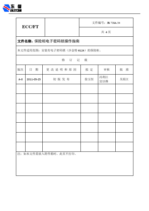
保险柜电子密码锁操作指南保险柜电子密码锁操作指南和注意事项一、注意事项:1)出厂初始密码是:123456和6543212)每次按电子锁键盘上数字、字母或其他字符时,都会发出“嘀嘀”声音,同时LED灯会闪烁。
如果没有响声和红灯闪烁,需要检查电源(电池)是否正常,连接线缆接触是否良好之后再尝试。
3)电子锁发出不同的声音反映不同的状态,再次输入密码或字母时必须保证前一次的声音已经停止。
4)当密码输入错误时,可以按“*”清除或等待10秒钟自动清除。
两次输入间隔时间不要超过10秒钟,否则将自动清除。
5)如果连续5次输入错误密码,电子锁有10分钟的惩罚时间,在此期间如再次输入密码错误将会听到(B,B长2声)锁无法打开,你需要再次等待10分钟。
6)不要选用生日或其他可以预知到的数字做用户和开启密码。
7)输入密码后锁连续发出“咔嚓、咔嚓”的声响,说明电子锁舌和锁板之间有干涉,这时请确认门把手是否处于垂直状态。
8)门罩壳有防拆装置,不许随意破坏,如碰到密码丢失或锁坏等情况,请联系二线工程师。
9)操作人员离开机器时一定要确认保险柜门是否锁上。
二、开启保险柜门1.插入保险柜钥匙,顺时针方向转动钥匙160°开启机械锁。
2.输入6位正确密码+“#”键。
3.逆时针转动保险柜手柄,可以打开保险柜门。
注意:钥匙打开后请勿动手柄。
三、关闭保险柜门:1.顺时针转动门手柄至垂直状态,电子密码锁10秒后自动锁定。
(听到B一声和LED灯闪烁)2.逆时针转动钥匙160°,确认保险柜门已锁定,拔出钥匙。
3.逆时针转动保险柜手柄,不能开启说明保险柜门已经关闭好。
四、修改密码:22*旧密码#新密码#新密码#【例】密码是123456修改为147258,输入:22*123456#147258#147258#注意:修改密码必须在保险柜门开启状态下进行。
五、更换电池:1.双手托住密码键盘,慢慢拔下键盘。
(注意:键盘和底座的有效距离是150mm,请勿用力过大否Array则会将排线拉断。
- 1、下载文档前请自行甄别文档内容的完整性,平台不提供额外的编辑、内容补充、找答案等附加服务。
- 2、"仅部分预览"的文档,不可在线预览部分如存在完整性等问题,可反馈申请退款(可完整预览的文档不适用该条件!)。
- 3、如文档侵犯您的权益,请联系客服反馈,我们会尽快为您处理(人工客服工作时间:9:00-18:30)。
密码锁的操作指南
(1)管理密码:设置和删除开门密码并开门
(2)开门密码:开门
(3)机械钥匙:应急开门、配管理卡
注:输入密码前先擦摸一下按键面板,背光蓝灯亮起后再输入密码。
1.更改管理密码步骤(出厂初始管理密码为:12345678):
A.输入8位初始管理密码后,按“1”键,门锁有转动声,“嘀”一声长鸣,背光蓝灯
中速闪烁;
B.按“1”键,“嘀”一声鸣响,背光蓝灯中速闪烁;
C.输入8位新的管理密码后,按“#”键,门锁有转动声,“嘀”一声鸣响,背光蓝灯
快速闪烁;
D.再次输入相同的8位新的管理密码后,按“#”键,背光蓝灯亮,“嘀”三声鸣响,
管理密码修改成功。
如果第二次输入密码与第一次的密码不同,按“#”键后,“嘀”
5声鸣响,之后可重新输入。
E.退出按“*”键。
2.配开门密码步骤
A.输入8位管理密码后,按“8”键,门锁有转动声,“嘀”一声长鸣,背光蓝灯中速
闪烁;
B.按“8”键,“嘀”一声鸣响,背光蓝灯中速闪烁;
C.输入新的开门密码(6—8位)后,按“#”键,门锁有转动声,“嘀”一声鸣响,面
板背光蓝灯快速闪烁;
D.再次输入相同的密码(6—8位)后,按“#”键,背光蓝灯亮,“嘀”二声鸣响,
开门密码修改成功。
如果第二次输入密码与第一次的密码不同,按“#”后,“嘀”
5声鸣响,之后可重新输入。
E.重复上述四步操作可以配50个开门密码,如果与前密码相同,则“嘀”4声鸣响。
F.退出按“*”键。
3.删除或修改开门密码步骤
A.删除单个开门密码:输入8位管理密码后,门锁有转动声,按“4”键,“嘀”一声
长鸣,面板背光蓝灯中速闪烁;
B.输入要删除的密码后,按“#”“嘀”一声长鸣,并自动退出该状态,删除成功;
C.删除所有开门密码:输入8位开门密码后,按“0”键,“嘀”一声长鸣,面板背光
蓝灯快速闪烁;再按“#”确认,门锁发出“嘀、嘀、嘀”三声长鸣,面板背光蓝灯闪烁,删除完成(即注销原来的所有开门密码)。
D.修改开门密码:输入8位初始管理密码后,按“1”键,“嘀”一声长鸣,面板背光
蓝灯中速闪烁;
E.输入新的开门密码(6—8位)后,按“#”,“嘀”二声鸣响,面板背光蓝灯快速闪
烁;
F.再次输入相同的密码(6—8位)后,按“#”,面板背光灯亮,“嘀”三声鸣响,并
自动退出该状态,修改成功,原开门密码失效。
如果第二次输入密码与第一次的密码不同,按“#”后,“嘀”5声鸣响,之后可重新输入。
G.退出按“*”键。
4.开门:
4.1 管理密码开门
输入管理密码后,按“#”,门锁“嘀”声,面板背光蓝灯慢速闪烁,提示门锁打开,然后,按下门把手开门;5秒钟后门锁未检测到开门动作,面板背光蓝灯熄灭,自动锁门。
4.2 开门密码开门
输入开门密码后,按“#”,门锁“嘀”声,面板背光蓝灯慢速闪烁,提示门锁打开,然后,按下门把手开门;5秒钟后门锁未检测到开门动作,面板背光蓝灯熄灭,自动锁门。
注:1、如果不是有效的开门密码,则门锁“嘀”3声短鸣,面板背光蓝灯立即熄灭,门锁仍然处于闭锁状态。
2、如果电池电压不足,则门锁“嘀”3声短鸣,红蓝灯闪烁,第一次低电压提示后,应注意更换电池。
特别提示:安装完成后应立即修改管理密码并删除所有开门密码。
本防盗密码锁支持开门乱码功能。
比如,开门密码为:159753,可以在开门输入密码时任意添加其它数字,如:481597531236,但不要超过12位。
感应卡锁的操作指南
(1)管理卡:设置和删除有效开门卡,可直接开门
(2)开门卡:开门及设置通道锁
(3)机械钥匙:应急开门、配管理卡
1.设置、删除管理卡:
1.1设置:门锁初始状态或数据清空状态下,刷的第一张卡,门锁“嘀”1声短鸣再“嘀”
1声长鸣,此卡即为管理卡,最多设置2张管理卡。
1.2删除:转动5下机械钥匙,面板背光蓝灯快速闪烁,“嘀”1声长鸣,清空所有卡和密
码。
2.配开门卡:
2.1进入配钥匙卡状态
刷管理卡,门锁“嘀”1声,电机转动声,面板背光蓝灯不闪烁,再刷管理卡1次,门锁“嘀”1声,面板背光蓝灯慢闪,进入配钥匙卡状态,此时刷的卡即为有效开门卡。
5秒钟内门锁如果没有检测到有效的感应卡,则门锁“嘀”2声短鸣,配卡结束。
2.2 配钥匙卡操作过程
进入配钥匙卡状态后,刷感应卡后,门锁“嘀”1声短鸣再“嘀”1声长鸣,配卡成功。
如果此卡已经存在,则门锁“嘀”2声短鸣。
最多可配200张卡。
3.删除开门卡
3.1删除单个开门卡:刷管理卡,门锁“嘀”1声,门锁有转动声,面板背光蓝灯不闪烁,
再连续刷管理卡2次,背光蓝灯中速闪烁,把要删除的开门卡刷1次,“嘀”1声短鸣再“嘀”1声长鸣,表示该卡被删除。
重复此操作可继续删除其它开门卡,如果此卡不存在,则门锁发出6声短鸣。
3.2删除单个遗失开门卡:刷管理卡,门锁“嘀”1声,门锁有转动声,背光蓝灯不闪烁,
再连续刷管理卡3次,背光蓝灯快速闪烁,把遗失的前一张卡靠近感应区刷一次,“嘀”
6声短鸣,表示该遗失卡已经被删除。
如果是第一张卡遗失,则有此状态下刷最后的一张开门卡。
3.3删除所有开门卡:刷管理卡,门锁“嘀”1声,门锁有转动声,背光蓝灯不闪烁,再连
续刷管理卡4次,则门锁发出“嘀”3声长鸣同时背光蓝灯闪烁,删除完成。
即注销原来所有的开门卡,原有效开门卡不能再开锁,只有通过管理卡重新配卡,方可开锁。
注:添加新的开门卡总是从最前面删除卡的位置往后排序。
4.开门:
4.1 感应钥匙卡开门:用有效的感应卡刷门锁的感应区,门锁“嘀”1声,门锁有转动声,背光蓝灯亮,提示锁已开,门锁检测到开门动作后,自动锁门,如果油松没到开门动作,5秒钟后背光蓝灯灭也自动锁门。
注:1、如果不是有效的感应开门卡,则门锁“嘀”6声短鸣,背光蓝灯立即熄灭,门锁仍然处于闭锁状态。
2、如果电池电压不足,则门锁“嘀”3声短鸣,红蓝灯闪烁,第一次低电压提示后,应注意更换电池。
4.2 机械钥匙开门:在电路发生故障的情况下或电池电压不足都可用机械钥匙开锁。
机械钥匙是设置管理密码和管理卡的关键,又可以直接开锁,建议放置其它地方妥善保管。