MPE720使用方法基础
YASKAWA_TO_mpe720软件操作方法

个别资料传送1 电脑---机器
选择 seleted files表 示个別资料传送
FROM MPE720 TO CONTROLLER表示 个别资料进行电脑到机器传送
个别资料传送2
Individual Load表示 个別资料传送画面
如需选择所要 Motion Main Program 程式打勾 表示主程式
能键
视窗功能键解说1
开启新档
开启旧档
存档
列印
套用坐标指令
故障表
视窗功能键解说2
储存档案至闪存
每指令自动加结束符(;)
坐标位置自动更新
视窗功能键解说3
(debug mode)功能键F1选择后机器 的控制权交由电脑控制
(regular mode)功能键F2选择后
机器的控制权交由机器控制
(F4)功能键STEP INTO 主程序內容 將单一自动执行
Tile---并列视窗
选择windows(W)双击Tile并列视窗即将坐标视窗 与本程式视窗合并与同一视窗,便与同时作业.
并列视窗作业
将程式视窗拉至坐标视窗 与work coordinate system平齐
呼叫功能键1
在视窗上选择 view
再选择 FUNCTIONG
BAR
呼叫功能键2
视窗出现 F1至F10功
Programs---开启机器內部绕线程式
2
MPM为主程
1
式档.MPS为 副程式档.
MPM251为原
点条件程式.
MPM252为回
原点程式此
两项程式不
3
4
可刪除或随 意修改.
MPM001---进入1号程式
MPE720Ver604新功能手册
Engineering Tool for MP2000 Series Machine Controller MPE720 Version 6USER'S MANUALNew Features of Version 6.04ContentsChapter 1 Motion Command Assist Function.............................................1-1 1.1 Motion Command Assist Function..........................................................1-21.1.1 Insert the Motion Command....................................................................1-2( 1 ) Input Motion Instruction..........................................................................1-21.1.2 Insert Servo Enable, Servo Disable, Alarm Clear Instruction.................1-4 Chapter 2 System Sub-window..................................................................2-12.1 System Sub-window...............................................................................2-2 Chapter 3 Test Run.....................................................................................3-13.1 Test Run..................................................................................................3-23.1.1 T est Run Procedure.................................................................................3-2 3.2 Servo Enable, Servo Disable.................................................................3-53.2.1 Servo Enable............................................................................................3-53.2.2 Servo Disable...........................................................................................3-5 3.3 Jog Operation.........................................................................................3-6( 1 ) Set the speed reference........................................................................3-63.3.1 Jog Forward.............................................................................................3-73.3.2 Jog Reverse.............................................................................................3-7 3.4 Step Operation........................................................................................3-83.4.1 Step Operation Procedure.......................................................................3-9 Chapter 4 Axis Monitor................................................................................4-1 4.1 Axis Monitor............................................................................................4-2 4.2 Axis Monitor Display...............................................................................4-34.2.1 T oolbar......................................................................................................4-34.2.2 Circuit and Axis Display...........................................................................4-3( 1 ) Circuit Display........................................................................................4-3 ( 2 ) Axis Display............................................................................................4-34.2.3 Status Display..........................................................................................4-4( 1 ) Ready, Enabled......................................................................................4-4 ( 2 ) Alarm, Warning.......................................................................................4-4 ( 3 ) Profile Complete, In Position.................................................................4-4 ( 4 ) Motion Command...................................................................................4-44.2.4 Monitor Parameter Display......................................................................4-5( 1 ) Monitoring the Monitor Parameters.......................................................4-5 Chapter 5 Alarm Monitor.............................................................................5-1 5.1 Alarm Monitor.........................................................................................5-25.1.1 Alarm Monitor Display..............................................................................5-3( 1 ) T oolbar....................................................................................................5-3 ( 2 ) Status......................................................................................................5-3 ( 3 ) Show, Hide the Circuit............................................................................5-35.1.2 When Alarm, Warning Occurs.................................................................5-4( 1 ) Alarm, Warning Information...................................................................5-5 Chapter 6 Additional Function of Compile Options.....................................6-1 6.1 Additional Function of Compile Options.................................................6-2 Chapter 7 Troubleshooting..........................................................................7-1 7.1 Troubleshooting......................................................................................7-2 7.2 Troubleshooting Flow.............................................................................7-37.2.1 Start Troubleshooting...............................................................................7-37.2.2 Troubleshooting Details...........................................................................7-4( 1 ) An operation error occurs in the program..............................................7-4 ( 2 ) I/O error occurs......................................................................................7-87.2.3 Complete the Troubleshooting (710)7.3 Error Codes..........................................................................................7-11 Chapter 8 Communications Setting............................................................8-1 8.1 Communication Setting..........................................................................8-2 8.2 Connect Using Ethernet.........................................................................8-28.2.1 Computer Setting.....................................................................................8-2( 1 ) Setting the IP Address...........................................................................8-28.2.2 Ethernet Port Setting................................................................................8-5( 1 ) How to Set an Ethernet Port..................................................................8-5 ( 2 ) How to Set an Ethernet (LP) Port..........................................................8-5 8.3 Connect Using Serial Port......................................................................8-78.3.1 Serial Port Settings..................................................................................8-7( 1 ) Setting of Serial Port..............................................................................8-7Chapter 1 Motion Command Assist FunctionThis chapter describes the "motion command assist function".1.1 Motion Command Assist Function...................................................1-21.1.1 Insert the Motion Command.......................................................................1-21.1.2 Insert Servo Enable, Servo Disable, Alarm Clear Instruction.....................1-41.1 Motion Command Assist FunctionThe Motion Command Assist Function helps to input motion instructions when creating the motion program.The motion program is described with a text-type Motion Language. Motion instructions should be input complying with their own format.Using the Motion Command Dialog Box, motion instructions will be easier to input.1.1.1 Insert the Motion CommandRight-click the mouse in the motion program editor. The pop-up menu will appear. The motion instructions can be selected and inserted from the pop-up menu. There are two methods to access the Motion Command Assist Function.● Select “Motion command assist...” from the pop-up menu :The Motion Command Assist Dialog Box is displayed. Select an instruction from the "command" column.● Select “Insert motion command” – “Instruction” from the pop-up menu :The Motion Command Assist Dialog Box is displayed. Select a motion instruction from the pop-up menu and itis displayed in the "command" column.( 1 ) Input Motion Instruction1. Right-click the mouse in the motion program editor and select “Insert motion command” from the pop-upmenu.The Motion Command Assist Dialog Box is displayed.2. Complete all settings and click the Insert button.The following two types of dialog boxes appear.Select Command ( )When clicking , the instructions which can be inserted are displayed. Select the instruction to be inserted.Motion instruction Format ( )The format of the selected instruction is displayed.Number of Axes ()Set the number of controlled axes. When the number of axes of selected instruction is a fixed number, the fixed number is displayed automatically and shown in gray.Refresh ( )Click the button to update the Motion Command Assist Dialog Box.Setting the arguments ( )The arguments of each motion instruction are displayed. Set the “axis name” and the “setting value” in the table.Arguments: The argument names are displayed.Axis: Set the logical axis name which is defined in the "group definition".Setting value: The constant and the register number can be input. If the setting value can be omitted, "Optional" is displayed as default.Unit: The unit of each argument is displayed.When the units are not set, is displayed. The tool tip help is displayed when the mouse pointer is held over the unit. Set the unit according to the instruction.Program code ( )This program code is displayed when the motion instruction does not need the "axis name" and "setting value".Comment ( )Comment column ( )If "Comment" is selected, it is possible to add and edit comments in the "Comment column" for each instruction. If not, "Comment column" is shown in gray.Insert ( )Click the button to insert the instruction.Close ( )Click the button to close the Motion Command Assist Dialog Box.Help ( )Click the button to display the "Machine Controller MP2200/MP2300 Motion Module User's Manual".1.1.2 Insert Servo Enable, Servo Disable, Alarm Clear InstructionThe Servo Enable, Servo Disable, and Alarm Clear instruction can be easily inserted without considering the motion register.1. Right-click the mouse in the motion program editor. Then select “Insert Motion Command” – “ServoEnable”, “Servo Disable” or “Alarm Clear” from the pop-up menu.The Axis Dialog Box is displayed.2. Select logical axis name from the Axis combo box. Then click the Insert button.3. The instruction (Servo Enable, Servo Disable or Alarm Clear) is inserted at the cursor position.Chapter 2System Sub-window This chapter describes the System Sub-window.2.1 System Sub-window........................................................................2-22.1 System Sub-windowThe System Sub-window manages the following functions.● Module configuration● Axis configuration- Test Run- Axis Monitor- Alarm Monitor- Motion Parameter ListChapter 3 Test RunChapter 3Test RunThis chapter describes how to use the Test Run function.3.1 Test Run...........................................................................................3-23.1.1 Test Run Procedure....................................................................................3-23.2 Servo Enable, Servo Disable...........................................................3-53.2.1 Servo Enable..............................................................................................3-53.2.2 Servo Disable..............................................................................................3-53.3 Jog Operation..................................................................................3-63.3.1 Jog Forward................................................................................................3-73.3.2 Jog Reverse................................................................................................3-73.4 Step Operation.................................................................................3-83.4.1 Step Operation Procedure..........................................................................3-93.1 T est RunThe Test Run function is for checking if the machine controller can operate an axis. It has three functions.- Servo Enable, Servo Disable: Enable or Disable the specified axis.- JOG: Jogs the specified axis with specified speed and direction.- STEP: Runs the specified axis a specified distance.The following two functions are implemented for monitoring.- Axis Monitor: Monitors the status of each axis.- Alarm Monitor: Monitors the "Alarm information" of all axes in one screen.♦ The Test Run function can be operated when the target axis has the following status.AxisMotion ControllerOperation ReadyServo ReadyMotion CommandResponse CodeServo ON ON NOPSVB built-in CPUSVB-01 Inverter - ON NOP SV A-01 ON ON NOP SVR ON - NOP PO-01 ON - NOPThe Test Run function may not work correctly when a motion program or sequence program operates theaxis.3.1.1 T est Run Procedure1. Double-click the T est Run Folder in the System Sub-window.A Test Run warning window will be displayed.2. Confirm the contents. Then click the Agree button.The Test Run Window and Axis Dialog Box is displayed.3. Select the target axis from the Axis Dialog Box. Then click the OK button.The following message is displayed.4. The selected Axis name is displayed in the right side of the “Axis...” button when clicking the “Yes” button.♦ The Test Run function can operate only one axis at a time.Axis monitor ( )The Axis Monitor Window is displayed in the Main Window.Alarm monitor ( )The Alarm Monitor Window is displayed in the Main Window.Update ( )Updates the display of the Test Run Window.Axis ( )The Axis Dialog Box is displayed.Status ( / ) The status of the axis is displayed.Enable ( )Click the button to enable the axis.Disable ( )Click the button to disable the axis.Monitor Status ( / / ) The operating status of the monitor will be displayed.Monitor ( )The Alarm Warning Dialog Box is displayed.3.2 Servo Enable, Servo DisableThe axis can be enabled and disabled with this function. The status of the axis can also be monitored in the Test Run Dialog Box.The way to operate and monitor the axis is described below.3.2.1 Servo EnableEnabling the axis and monitoring the status.1. Click the Enable button.The axis is enabled.Axis status is changed to "Enabled".The operation of Jog and Step becomes available.3.2.2 Servo DisableDisabling the axis and monitoring the status.1. Click the Disable button.The axis is disabled.The status is changed to "Disabled".Jog and Step cannot be used.3.3 Jog OperationThe Jog operation is a function to run the forward or reverse direction of the axis. The running speed can be set in theSpeed reference Dialog Box.Jog is available only while the axis is enabled.The axis will run while the Forward or Reverse button is pressed. The axis will stop when the Forward or Reversebutton is released.Speed reference ( )The Speed reference Dialog Box is displayed, and the running speed (speed reference) is set in the dialog box. Forward ()The axis runs forward. Reverse ()The axis runs reverse.( 1 ) Set the speed reference1. Click the Speed reference button.Speed reference Dialog Box is displayed.2. Input speed reference. Then click the Set button.♦When the unit is not set, the following dialog box is displayed. Click the Open button to set the unit.3.3.1 Jog ForwardThe axis runs forward while the button is held down.1. Hold down the Forward button with the mouse.The axis runs forward.2. Release the button.The axis stops.3.3.2 Jog ReverseThe axis runs reverse while the button is held down.1. Hold down the Reverse button with the mouse.The axis runs reverse.2. Release the button.The axis stops.3.4 Step OperationThe step operation moves the axis a specified distance and then stops.The axis starts moving when the Run button is clicked. Motion can be aborted with the Stop button.The step operation can also repeat round trip motion several times.The step operation operates under the following conditions.● Servo is enabled.● The speed reference and step distance must be set.The "---" is displayed by default. If the Forward Reverse button is operated before setting them, the following error message is displayed.● The unit for speed reference and step distance must be set.The unit of speed reference and step distance is related to some fixed parameters. If changing the unit of one, theunit of the other is also changed.The following error message is displayed if the unit is not set. To set the unit, click the Open button.3.4.1 Step Operation ProcedurePlease refer to "3.2 Servo Enable, Servo " to learn how to enable or disable servo.1. Click the “Step” T ab.The Step Setting Dialog Box is displayed.2. Click the “Speed reference”, “Step distance” and “Direction setting” button and set them.Speed reference ( )Display Speed reference Dialog Box and set speed reference.Step distance ( )Display the Step distance Dialog Box and set the step distance.♦ When the Step distance unit is not set, a fixed parameter of the Motion module is automatically read.Direction setting ( )Display the Direction Setting Dialog Box and set the direction.Direction: Set the direction for first motion.Repetitive running: Check it for repeat operation.Repeat time: Set the number of times to repeat.i.e. Repeat time is 2.Forward -> Reverse -> Forward -> Reverse.Repeat stop time: Set the interval time between motion.Forward Reverse (/ , / ) " " shows the direction of motor.Repeat time ( )"Current repeat time/ Setting repeat time" is displayed.Run ( )To start the step operation.Stop ( )To stop the step operation. The following message is displayed when stopped.3. Click the Run button.The step operation starts.Chapter 4Axis Monitor This chapter describes how to use the Axis Monitor.4.1 Axis Monitor.....................................................................................4-2 4.2 Axis Monitor Display........................................................................4-34.2.1 Toolbar........................................................................................................4-34.2.2 Circuit and Axis Display..............................................................................4-34.2.3 Status Display.............................................................................................4-44.2.4 Monitor Parameter Display.........................................................................4-54.1 Axis MonitorThe axis monitor is a function to monitor the status of each axis in the "Axis Monitor" window.The status (Ready, Enable, Alarm, Warning, Profile Complete, In Position, Motion Command) and other extended monitoring parameters can be monitored.The axis monitor updates when displayed in the Main Window. Scrolling displays other axes and parameters which are out of the window.♦ The axes displayed:SVB: The axes which are connected via MECHATROLINK.SVA-01: 2 axes.PO-01: 4 axes.SVR: 16 axes.4.2 Axis Monitor DisplayThe display of the Axis Monitor Window is described below.4.2.1 T oolbarCircuit ( )Monitoring the selected circuit.Monitor type ( / / )The update cycle can be chosen from "High Speed, Normal Speed, Low Speed".Monitoring ( / )Click the button to select stop or start monitoring.Alarm monitor ( )Click the button to display the Alarm Monitor window.Refresh ( )Click the button to update the Axis Monitor window.4.2.2 Circuit and Axis Display( 1 ) Circuit DisplayThe motion module number (SVB, SV A, PO-01, SVR) of the axis and module name are displayed. ( 2 ) Axis DisplayThe axis name and the product type of axis are displayed.4.2.3 Status DisplayThe status of the Ready, Enable, Alarm, Warning, Profile Complete, In Position and Motion Command are displayed. ( 1 ) Ready, EnabledThe status is displayed.Ready ( / ) : The status if the axis is ready to operate.Enabled ( / ) : The status if the axis is enabled.( 2 ) Alarm, WarningThe status of the alarm and warning are displayed.[Alarm, warning status]No Alarm ( ) : No alarm or warning.Alarm ( ) :Alarm has occurred.Warning ( ) : Warning has occurred.Clicking the "status" displays the Alarm Warning Dialog Box. Details of the alarm and warning are displayed. Refer to "Chapter 5: Alarm Monitor" for more information on the Alarm/Warning monitoring function.( 3 ) Profile Complete, In PositionThe status of Profile Complete and In Position are displayed. When Profile Complete or In Position signal is ON, the lamp is displayed in blue.Profile Complete ( / ) :The status of the Profile Complete.In Position ( / ) :The status of the In Position.( 4 ) Motion CommandThe status of the motion command response code is displayed. The background is displayed in blue except "---"(NOP).4.2.4 Monitor Parameter DisplayThe monitor parameters are displayed. The displayed parameters are chosen by selecting from the list or inputting the register number (Only I/O).In default, Machine coordinate feedback position (APOS), Position error (PERR), Feedback speed, and Feedback torque/ thrust are displayed. Eight parameters can be displayed at the same time.The selection of displayed parameters is saved in the project file. Therefore, when opening the Axis Monitor window again, the same parameters will be displayed.( 1 ) Monitoring the Monitor Parameters1. Click the Monitor Parameter button ().The Monitor Parameter Dialog Box is displayed.2. Select a parameter from the combo box or input a register number (Only I/O) directly.Monitor parameters which are selectable from the combo boxMonitor Parameter Register UnitMachine coordinate target position (TPOS) ILxx0E Reference unitTarget position (CPOS) ILxx10 Reference unitMachine coordinate system position (MPOS) ILxx12 Reference unitMachine coordinate feedback position (APOS) ILxx16 Reference unitunit Machine coordinate latch position (LPOS) ILxx18 ReferencePosition error (PERR) ILxx1A Reference unitPOSMAX number of turns ILxx1E [rev]Speed reference output monitor ILxx20 [pulse/sec]Feedback speed ILxx40 Speed unit selectionFeedback torque/ thrust ILxx42 Torque unit selection3. Click the OK button.The monitor parameters are displayed.Chapter 5Alarm Monitor This chapter describes how to use the Alarm Monitor.5.1 Alarm Monitor...................................................................................5-25.1.1 Alarm Monitor Display.................................................................................5-35.1.2 When Alarm, Warning Occurs....................................................................5-45.1 Alarm MonitorThe Alarm Monitor window displays the alarm information of all axes in one window. The status of alarm, warning and alarm code are displayed.When an alarm or warning occurs, status is displayed as or . When no alarm or warningoccurs, it is displayed as .Clicking "status" displays the Alarm Warning Dialog Box. As a result, detailed information of the alarm and warning can be confirmed.♦ All the monitor data displays by “-----" when off-line.The status and alarm code are displayed in each circuit number. The Alarm Monitor can display the information of up to eight axes horizontally.5.1.1 Alarm Monitor Display( 1 ) T oolbarIn the toolbar, there are two icons to refresh manually and start/stop monitoring.Manually refresh ( )Alarm and warning information in the Alarm Monitor window is updated manually.♦ The Alarm Monitor Window is not refreshed automatically.Monitoring ( / )Click the button to stop or start the monitoring.( 2 ) StatusWhen an alarm or warning occurs, the status of the alarm or warning is displayed as shown below.Alarm ( ) :Alarm is occurring.Warning ( ) : Warning is occurring.No Alarm ( ) : No alarm or warning.( 3 ) Show, Hide the CircuitThe monitoring data of each circuit can be shown or hidden by clicking the circuit number. As a result, only selected axes can be displayed.i.e. Showi.e. Hide5.1.2 When Alarm, Warning OccursClick the status in the Alarm Monitor window. The Alarm/ Warning Dialog Box is displayed.Clicking the "Help" button displays detailed information of the alarm or warning. Correct the alarm by checking"help". Then click the Alarm Clear button to reset the alarm.Axis name ( )"Axis number", "comment" and "product type" are displayed in order. Alarm, warning name ()The Alarm or Warning name is displayed. Alarm clear ()To clear the alarm.Help ( )The description of the occurring alarm in the manual "Machine Controller MP2200/MP2300 Motion Module User's Manual" is displayed.Refresh ( )To update the Alarm, Warning Dialog Box. Alarm, Warning ()The BIT number, the parameter name, and the status are displayed. Close ( )To close the Alarm, Warning Dialog Box.( 1 ) Alarm, Warning InformationAll alarms and warnings are displayed in the Alarm, Warning display Dialog Box.Chapter 6 Additional Function of Compile OptionsThis chapter describes an additional function of compile options.6.1 Additional Function of Compile Options..........................................6-26.1 Additional Function of Compile OptionsThe ladder program "Compile Options" can be set without displaying the ladder program in this version or later.Select "Ladder" – "General" from the tree in the Environment Setting Dialog Box and the Compile Option settings are displayed.ProgramCreate new CP ladderWhen "Use" is selected, "Create new CP ladder" is displayed in Ladder Sub-window popup menus.Compile OptionThe option for compiling the ladder program is selected. The Compile Option can be set without displaying the ladder program.Enable Multiple Coil Check:When "Enable" is selected, duplicate coils in the target program are checked during the compile.Compile to Ver.5 Compatible:When "Enable" is selected, ladder programs compiled with MPE720 version 6 can be displayed and editedwith MPE720 version 5 (V ersion 5.34 or later).Chapter 7Troubleshooting This chapter describes how to use the System Monitor function to find errors in the program.7.1 Troubleshooting...............................................................................7-2 7.2 Troubleshooting Flow......................................................................7-37.2.1 Start Troubleshooting..................................................................................7-37.2.2 Troubleshooting Details..............................................................................7-47.2.3 Complete the Troubleshooting (710)7.3 Error Codes...................................................................................7-11。
MPE使用方法基础专题培训课件
3-2. Serial RS-232C 設定
双击欲設定之的Logical PT Communication Manger 共支援16組 Logical PT
在 Port Kind 选项 选择 Serial 按下 Detail 可进入详细设定
3. MPE720 與 MP2000 的連線
RS-232C
1. MP2000 控制器架構介紹
Ladder program Motion program
MPE720
MP2000 series
Communication manager
Module configuration
4
2. Self configuration 与初期设定的动作介绍
5
2. Self configuration 與初期設定的動作介紹
重新關開一次 Communication Manger
20
3-2. Serial RS-232C 設定
在MPE720 主画面下, 的 Controller 选项內, 按下 Communication Setting
在 Communication port 选择所设定的 Logical PT
再按下 Connection 即可 完成连线
MPE720使用方法基 础
目录
1. MP2000 控制器架构介紹 2. Self configuration 与初期设定的动作介绍 3. MPE720 与 MP2000 的连接 4. MPE720 各项功能说明 5. System 说明
2
1. MP2000 控制器架构介紹
3
1-1. MP2000 控制器架构介绍
MP2200 / MP2300 MP2300S / MP2310
安川PLC mpe720模块 lio 01 04
信号 N.C. N.C.
备注 未连接 未连接
编号 6 7 8
信号 N.C. N.C. SIG+
备注 未连接 未连接 发送/接收 数据(+)
连接器为 Honda 通讯实业有限公司生产的 MR-8RFA4(G)。 连接使用 MR-8M(G) (壳体:MR-8L)
4.3.4 CP-216IF 模块
CP-216 传输用于换流器,CP-816 RIO-01 和 RIO-06 控制传输使用我们的 4Mbps 高速现 场网络,按照标准 300 米的传输距离内可以连接 8 个换流器。 ■ 指示灯 如果模块运行正常, RUN LED 亮, ERR LED 灭。 如果出现错误, RUN RED 不亮, ERR LED 亮或闪烁。TX LED 在发送数据时亮。 指示 RMV RUN ERR TX 名称 拆除 运行 错误 总线 TX 指示灯颜色 绿色 绿色 红色 绿色 点亮时状态 可以拆除模块 正常运行时亮 出现错误时亮或闪烁 通过 CP-216 发送数据时亮
状态 ON OFF ON OFF ON OFF ON OFF ON OFF ON OFF ON OFF ON OFF
运行 网络编号பைடு நூலகம்
网络编号 A0 A1 A2 A3 A4 A5 A6 A7
1
ON OFF OFF OFF OFF OFF OFF OFF
2
OFF ON OFF OFF OFF OFF OFF OFF
■ 终端块(TSB1/RUN) 终端块用于报警输出。它是开放集电器输出。在输入正常的 5VDC 时出现短路。 指示 OC OUT 名称 1 2 0V 状态输出 (正常输出中的短路) 运行 输入电压 电流值 规格 24VDC 50mA(最大)
高速摄像机i-SPEED720中文说明书

1 yr (std) /2 yr / 3 yr
2x 14.4v 90Wh
Resolution
2048x1536 2048x1536 2048x1536 2048x1536 2048x1536 2048x1536 2048x1536 2048x1536 1920x1080 1440x1080 1280x720 1000x568 676x480 560x277 560x127 560x82 560x37 560x22
, -4 to 140 , -20 to 60
71 kpa to 106 kpa G-shock, G-shock, 95% at 104°F 10G 30G @ 11ms IEC 68-2-27 Ea, 30G @ 2ms IEC 68-2-29 Eb 6pin Lemo BNC 75ohm 18pin Lemo, Trigger in / Sync in / Sync out / Exposure out / Remote power
W
SSD
w
14.3 ( ) x 6.2 ( ) x 6.2 ( ) 363 ( 12-36V 150w ¼x20 1 , 200w 3/8x16
) x 157 ( ) x 154 (L)
18.7lb (8.5kg)
,
FPS
100 200 300 500 1000 2000 5,000 6,350 9,600 12,500 20,000 30,000 50,000 100,000 200,000 300,000 500,000 750,000
o
TTL T0 to 0-100% , ROC, BROC 24Hz – 500kHz
s S
i-SPEED Viewer i-SPEED C++, LabView b , i-SPEED Viewer
安川PLCMPE720使用方法基础共72页文档

51、没有哪个社会可以制订一部永远 适用的 宪法, 甚至一 条永远 适用的 法律。 ——杰 斐逊 52、法律源于人的自卫本能。——英 格索尔
53、人们通常会发现,法律就是这样 一种的 网,触 犯法律 的人, 小的可 以穿网 而过, 大的可 以破网 而出, 只有中 等的才 会坠入 网中。 ——申 斯通 54、法律就是法律它是一座雄伟的大 夏,庇 护着我 们大家 ;它的 每一块 砖石都 垒在另 一块砖 石上。 ——高 尔斯华 绥 55、今天的法律未必明天仍是法律。 ——罗·伯顿
1、最灵繁的人也看不见自己的背脊。——非洲 2、最困难的事情就是认识自己。——希腊 3、有勇气承担命运这才是英雄好汉。——黑塞 4、与肝胆人共事,无字句处读书。——周恩来 5、阅读使人充实,会谈使人敏捷,写作使人精确。——培根
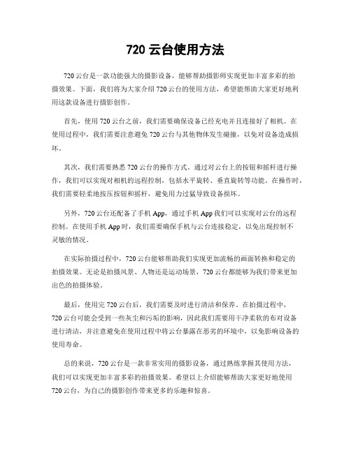
720云台使用方法
720云台使用方法
720云台是一款功能强大的摄影设备,能够帮助摄影师实现更加丰富多彩的拍
摄效果。
下面,我们将为大家介绍720云台的使用方法,希望能帮助大家更好地利用这款设备进行摄影创作。
首先,使用720云台之前,我们需要确保设备已经充电并且连接好了相机。
在
使用过程中,我们需要注意避免720云台与其他物体发生碰撞,以免对设备造成损坏。
其次,我们需要熟悉720云台的操作方式。
通过对云台上的按钮和摇杆进行操作,我们可以实现对相机的远程控制,包括水平旋转、垂直旋转等功能。
在操作时,我们需要轻柔地按压按钮和摇杆,避免用力过猛导致设备损坏。
另外,720云台还配备了手机App,通过手机App我们可以实现对云台的远程
控制。
在使用手机App时,我们需要确保手机与云台连接稳定,以免出现控制不
灵敏的情况。
在实际拍摄过程中,720云台能够帮助我们实现更加流畅的画面转换和稳定的
拍摄效果。
无论是拍摄风景、人物还是运动场景,720云台都能够为我们带来更加
出色的拍摄体验。
最后,使用完720云台后,我们需要及时进行清洁和保养。
在拍摄过程中,
720云台可能会受到一些灰尘和污垢的影响,因此我们需要用干净柔软的布对设备
进行清洁,并注意避免在使用过程中将云台暴露在恶劣的环境中,以免影响设备的使用寿命。
总的来说,720云台是一款非常实用的摄影设备,通过熟练掌握其使用方法,
我们可以实现更加丰富多彩的拍摄效果。
希望以上介绍能够帮助大家更好地使用720云台,为自己的摄影创作带来更多的乐趣和惊喜。
安川PLCMPE720使用方法基础
3-2. Serial RS-232C 設定
RS-232C
連擊欲設定之 Logical PT Communication Manger 共支援16組 Logical PT
在 Port Kind 選項
選擇 Serial 按下 Detail 可進入詳細設定
16
3. MPE720 與 MP2000 的連線
13
3. MPE720 與 MP2000 的連線
3-1. Communication manger 設定
初次通信設定 執行電腦中的通信程式 “開始”
“所有程式”
“YE Applications” “Communication Manager”
執行完後, 在右下角會出現
Communication manager Icon 電腦要和控制器通信時, 需此程式 長駐執行.
再按下 Connection 即可
完成連線
21
3. MPE720 與 MP2000 的連線
3-2. Serial RS-232C 設定
右圖為 MP2000控制器 透過 RS-232C 與PC連線 通信線之腳位接續圖
22
3. MPE720 與 MP2000 的連線
3-3. Ethernet 設定
Ethernet
完成連線
28
3. MPE720 與 MP2000 的連線
3-3. Ethernet 設定
MPE720 編輯畫面中 上方會顯示目前 連線狀態 與 CPU 狀態 綠色 連線中 CPU RUN 灰色 離線 紅色 通信異常 藍色 連線中 CPU STOP
通信中斷
連線中 CPU STOP 連線中 CPU RUN 離線
3-2. Serial RS-232C 設定
- 1、下载文档前请自行甄别文档内容的完整性,平台不提供额外的编辑、内容补充、找答案等附加服务。
- 2、"仅部分预览"的文档,不可在线预览部分如存在完整性等问题,可反馈申请退款(可完整预览的文档不适用该条件!)。
- 3、如文档侵犯您的权益,请联系客服反馈,我们会尽快为您处理(人工客服工作时间:9:00-18:30)。
3-2. Serial RS-232C 設定
若使用 USB轉Serial 傳輸方式 Physical Port 的確認方式
“我的电脑” “內容” “硬体” “裝置管理員”
3. MPE720 與 MP2000 的連線
18
3-2. Serial RS-232C 設定
在 装置管理员 內 选择 连接埠(COM和LPT) 可以确认 USB转 Serial 对应的COM port 编号
执行完后, 在右下角会出现 Communication manager Icon 电脑要和控制器通信時, 需此程序 长期执行.
14
3. MPE720 與 MP2000 的連線
3-1. Communication manger 設定
双击 Communication manager Icon , Communication manager 应用程序即会出现 在此应用程序內, 即可执行各种 与控制器连接方式的设定.
15
3-2. Serial RS-232C 設定
双击欲設定之的Logical PT Communication Manger 共支援16組 Logical PT
在 Port Kind 选项 选择 Serial 按下 Detail 可进入详细设定
3. MPE720 與 MP2000 的連線
RS-232C
2-2. 伺服驱动器的站址设定
实际对应站址
MP2000 系列 M-II 通信最大對應站數 21 站(最大伺服軸數 16 軸)
9
2. Self configuration 與初期設定的動作介紹
2-3. 控制器 CPU指挥开关定义
MP2200 / MP2300 MP2300S / MP2310
10
2. Self configuration 與初期設定的動作介紹
MP2200 / MP2300 MP2300S / MP2310
Self configuration 执行完成指示灯判別
: 閃爍 12
3. MPE720 与 MP2000 的连线
13
3. MPE720 與 MP2000 的連線
3-1. Communication manger 设定
初次通信设定 执行电脑中的通信程序 “开始” “所有程式” “YE Applications” “Communication Manager”
16
3-2. Serial RS-232C 設定
设定RS-232C通信协议 Physical Port Unit No Baud Rate Data Bits Parity Stop Bits
设定完成后, 按 OK 再按 Logical Port Setting OK 按鍵, 即完成设定
3. MPE720 與 MP2000 的連線 17
6
2. Self configuration 與初期設定的動作介紹
2-2. 伺服驅動器的站址設定
SW1
伺服驱动器
打开伺服驱动器前盖
站址设定旋转开关 SW2
M-II 協定设定开关 7
2. Self configuration 與初期設定的動作介紹
2-2. 伺服驱动器的站址设定
SW1
SW2
8
2. Self configuration 與初期設定的動作介紹
2-4. 执行程序初始化与 Self configuration 动作
MP2200 / MP2300 MP2300S / MP2310
Self configuration 的动作程序
11
2. Self configuration 與初期設定的動作介紹
2-4. 执行Self configuration 动作
1. MP2000 控制器架構介紹
Ladder program Motion program
MPE720
MP2000 series
Communication manager
Module configuration
4
2. Self configuration 与初期设定的动作介绍
5
2. Self configuration 與初期設定的動作介紹
3. MPE720 與 MP2000 的連線 21
3-2. Serial RS-232C 設定
右圖為 MP2000控制器 透過 RS-232C 與PC連線 通信線之00 的連線
22
3-3. Ethernet 設定
双击欲设定的 Logical PT Communication Manger 共支援16組 Logical PT
2-1. Self configuration 的动作目的
Self configuration 的功能, 主要的目的是在初期设定时控制器会针对 硬体插槽, 以及通信连接上有偵測到的裝置做判断的动作.让使用者在初 期设定时, 不必要做太多繁杂的设定, 并可节省初期設定的时间. 透過控制器自我架构化的动作, 也可以減少人为设定的疏失, 以減少在 程序编辑与执行中发生不合理的异常现象.
重新關開一次 Communication Manger
20
3-2. Serial RS-232C 設定
在MPE720 主画面下, 的 Controller 选项內, 按下 Communication Setting
在 Communication port 选择所设定的 Logical PT
再按下 Connection 即可 完成连线
MPE720 使用教育訓练 基础篇
1
目录
1. MP2000 控制器架构介紹 2. Self configuration 与初期设定的动作介绍 3. MPE720 与 MP2000 的连接 4. MPE720 各项功能说明 5. System 说明
2
1. MP2000 控制器架构介紹
3
1-1. MP2000 控制器架构介绍
3. MPE720 與 MP2000 的連線
19
3-2. Serial RS-232C 設定
3. MPE720 與 MP2000 的連線
關閉 Logical Port Setting 後, 會顯示設定內容
若有初次變更設定, 需要關閉 Communication Manger後, 再開啟一次, 所變更設定才會 生效. 開啟後可確認 Status 內容會變成 Ready 即完成 Serial RS-232C通信 設定