48V直流系统用户手册
48V说明书4806.01.20

接线
小电流连接
在KZQ-48T-400控制器上装有3个弱电插座,装于控制器顶部。
24针插座提供了逻辑控制连接。插头是24针插头,匹配的是24P.5557端子壳、端子。
0-5V的电源也可用来作滑动端输入(见图5)。但是,最大最小电压不能超过4.5V和0.5V的故障限值。对4型加速器来说,控制器不需要前进或后退的方向信号,方向由滑动端输入电压值决定。加速器对控制器的接口类似于2型加速器。
故障输出连线
KZQ-48T-400型控制器在5脚和6脚有2路故障输出驱动器,它们可以给车上的显示器或远程提供诊断信息。在标称电池电压时。这些输出的最大电流为10mA。这些输出的编程信息见第三节:可编程参数。
辅助接触器驱动器
和主接触器驱动器一样,辅助接触器(18脚)在互锁输入有效时被拉低,如果保持电压被设成小于100%,输出电压与主、反向信号,电磁制动接触器驱动器一起被脉宽调制成设定的线圈保持电压值。
如果需要可以把辅助接触器掉电延迟参数设成在互锁信号被禁止后最大保持40秒依旧有效。见图10所示。
反向信号驱动器
电流源加速器
电流源可以作为加速器,如图7所示。一个电阻R用来把电流源电流转换成电压,该电阻应该可以在电流满程范围内提供0-5V可变电压。
0-5K加速器(3型)
0—5K加速器(菜单上为3型),
是一个两线电阻型加速器,连在2线电位器和电位器低端脚(16脚和14脚)间。如图8所示。0速时为5千欧,这种输入不能用于往返型。
标准控制连线
AGV智能充电站用户手册(48V50A)

锂电池充电站THC-20-48V/50A用户手册2016年12月1 概述该充电系统是我公司根据智能机器人用磷酸铁锂蓄电池组的充电技术要求,开发研制的一种智能充电装置。
该设备采用可编程序控制器作为主控单元,7英寸彩色液晶触摸屏作为人机交换平台;主电路采用高频开关电源电路,重量轻、体积小、效率高、稳压稳流精度高等特点。
整套设备操作方便、工作可靠、保护齐全、自动化程度高。
提供485通信接口及外控接点,给上位机适时交换数据及工作状态.1.1 额定技术参数1)交流输入电压: AC220V±10% 50Hz2)直流输出电压: DC 20-60V3)直流输出电流: DC 2-50A4)纹波:≤1%5)稳流精度:≤±1%6)稳压精度:≤±1%7)噪声:≤55dB(关闭前后门1米处)8)冷却方式:风冷9)外型尺寸高1200mm×宽600mm×厚500mm1.2 使用条件1.2.1海拔不超过2000m。
1.2.2 环境温度不低于-10℃,不高于+50℃。
1.2.3 空气最大相对湿度不超过90%(在相当于空气温度20±5℃时)1.2.4 运行地点无导电及爆炸尘埃,无腐蚀金属和破坏绝缘的气体或蒸汽,无强2电磁干扰。
1.2.5 空气流通较好的场所。
1.2.6 无剧烈振动和冲击,垂直倾斜度不超过5º。
2工作原理本设备主电路采用高频开关电源电路。
单相交流经整流调整后变为稳压稳流直流电并由控制中心发出命令给电池组充电。
高频开关电路以数字电路为基础,对系统输出电压、电流反馈信号先进行隔离放大并与给定信号比较后,将其误差信号进行模数转换成数字信号,输入到逻辑处理单元和其它控制信号一同进行逻辑控制、适时计算最终发出触发脉冲,从而保证其准确性、可靠性。
用户可通过触摸屏人机界面来指示设备轻松完成对蓄电池组的快速充电、均衡充电等任务。
3安装3.1安装装置到达安装地点后,小心开箱。
48V监控系统说明书V1.1 (英文)

Battery detector (optional) Switch module
DCXJ-24-48V KGL-64-48V
Detects 24 batteries the voltages, 1 temperature Detects 64 DI, 8 DO, max 4 pcs in one system
General data acquisition module (choose either)
ZHCL-2-48V
Detects 3 DC voltage, 2 current,1 temperature Detects 24 DI, 8 DO
Detects 2 AC voltage ZHCL-3-48V Detects 6 DC voltage, 4 current,2 temperature Detects 32 DI, 8 DO
Name HOST unit Charger
Model THJK002G-3S-48V AC-DC/ DC-AC
Function summary Blue color 240*64 pixels LCD, key option AC-DC applicable for charging system DC-AC applicable for integrated system Optional Detest 1 AC voltage
Detect 24 batteries, detection range, 0-16V Detect 1 battery temperature 1.2.5 KGL-64-48V unit
Detects 64 DI, 8 DO
1.3 Typical solution
1.3.1 Battery management system
48V监控系统说明书V1.1 (英文)
WENZHOU ROCKWILL ELECTRICCO.,LTD.DC Battery Bank-GZDW48V Controller System InstructionChapter 1 overview1.1 System configurationTHJK002G-48V monitor and control system is composed of two parts, the host controller THJK002G-3S-48V and data acquisition module, including charger, general data acquisition module, battery detection module, switch module and etc. Shown in table 1-1NOTE :(40-60)VDC power supply only, charger module exception. Bus and battery can not be grouped.1.2 Function introduction 1.2.1 THJK002G-3S-48V host unitBlue color 240*64 pixels LCDOptional English language, key operation, easy for parameter settings andinformation inquiry.RS485, RS232 interface optional, communication protocol CDT, MODBUS The real-time clock demonstrated, after power failure clock normal operation. May save 200 alarm logs, 48 work logs, after the power failure the informationdoes not lose.Battery charge management function and integrated system use1.2.2 ZHCL-2-48V unitDetects 1 3-phases AC voltage input.Detects 3 DC voltage, 2 current,1 battery temperature. Detects 24 D/I, 8 D/ONameModelFunction summaryHOST unitTHJK002G-3S-48VBlue color 240*64 pixels LCD, key option ChargerAC-DC/ DC-ACAC-DC applicable for charging systemDC-AC applicable for integrated system OptionalGeneral data acquisition module (choose either)ZHCL-2-48VDetest 1 AC voltageDetects 3 DC voltage, 2 current,1 temperature Detects 24 DI, 8 DO ZHCL-3-48V Detects 2 AC voltageDetects 6 DC voltage, 4 current,2 temperature Detects 32 DI, 8 DOBattery detector (optional)DCXJ-24-48VDetects 24 batteries the voltages, 1 temperatureSwitch moduleKGL-64-48V Detects 64 DI, 8 DO, max 4 pcs in one system1.2.3 ZHCL-3-48V unitDetects 2 3-phases AC voltage input.Detects 6 DC voltage, 4 current, 2 battery temperature.Detects 32 D/I, 8 D/O1.2.4 DCXJ-24-48V unitDetect 24 batteries, detection range, 0-16VDetect 1 battery temperature1.2.5 KGL-64-48V unitDetects 64 DI, 8 DO1.3 Typical solution1.3.1 Battery management systemApplicable for 48V battery and charging system and application useSystem configuration: 48V charger module, ZHCL-2-48V/ ZHCL-3-48V,KGL-64-48V, DCXJ-24-48VThe sample signal gathered by ZHCL module, the charging curve and optional module (KGL-64-48V、DCXJ-24-48V), see the following instruction.1.3.2 Integrated systemApplicable for system without battery charging management function,System configuration: 48V charger module, ZHCL-2-48V/ ZHCL-3-48V, KGL-64-48V Sample signal gathered by ZHCL module, optional(KGL-64-48V), see following instruction.1.4 Working environment●The work ambient temperature is not lower than - 5℃, is not higher than +40℃, theequipment saves ambient temperature permission for - 10℃~+60℃.●The work environment maximum relative humidity does not ≤90% (ambienttemperature is 25℃).●The movement place non-electric conduction dust, does not have the dipping and thedestruction insulation gas or the steam.●In door use only●Remark when place order if any special request.Chapter 2 THJK002G-3S-48V2.1Features2.1.1 Human interfaceBlue color 240*64 pixels LCD,Optional English menu, key operation, easy for settings and information inquiry2.1.2 Alarm informationAlarm text display, identify fault, max 50 current alarm texts.200 history fault records, do not lose once power failureAlarm indication, when alarm occurs, the LCD screen light, the buzzer sound.The alarm threshold is settable2.1.3 Battery managementWhen AC power supply input, charge the battery automatically according to preset parameters.Can work with battery detector DCXJ to detect the battery cell voltage, 24 cells, 1 group Manage charging process of one battery bankPerfect charing and discharging protection function2.1.4 Switch DI/DO16 DI, which the user can choose to define.Choose the switch type (alarm or state) and define the initial number8 DO, which the user can choose to define.2.1.5 PC end communicationInterface: RS232 or RS485.Protocol: MODBUS.Baud rate: 2400、4800 or 9600.Address range 01~99.2.1.6 Others48 working logs, record running information every half an hour. the information does not lose once power failure.If there is no key-press operation within 4 minute, then runs screen protection.The real-time clock demonstrated, after power failure clock normal operation.2.2 THJK002G-3S-48V interfaceFig 2-1 THJK002G-3S-48V front panelFig 2-2 THJK002G-3S-48V rear panelMark DescriptionESC Function key在不同的显示界面下有不同的定义,……ENT Function keyRUN When power on,the green LED light on.ALM When there is fault, the red LED flashRST Reset key.COM2 RTU RS485 interface.COM1 PC end communication RS232 1-RXD 2-TXD 3-GNDRS485 4-485A 5-485BPower supply Input power, range 40~60VDC, power ≤15WTable 2-1 THJK002G-3S-48V interface definition2.3 Operation instructionTwo working mode: integrated working mode, and battery management mode, which set by through the host monitor (parameter set--input type)2.3.1 integrated system operation instructionSetting method: parameter set→special set→input type set “DC IN” . Menu display structure, easy operation.2.3.1.1 basic operationEnter host interface after powered on. Shoe the system time, bus voltage, load currentand current fault.Time:Jan 1st, 2013 12:12:12Bus:voltage 53.2 V Load:0.0AFault: NonePress “ENT”, come to main interfaceInformationPara SettingSys ControlPassword Setting2.3.1.2 InformationShow the information inquiry menu. Press “▲” “▼” to move cursor and “enter”and get the following menu .1 AC info 5 History fault2 Charger info 6 Current fault3 Switches info4 Running logAC infoShow the system input voltageDC input 220.0VCharger infoShow the output voltage, current, working state (RUN/OFF)01#:Voltage 48.0V Current 10A RUN02#:Voltage 48.0V Current 10A RUN03#:Voltage 48.0V Current 10A RUN04#:Voltage 48.0V Current 10A RUNSwitches infoCheck switches info of ZHCL module, KGL moduleThe state of user defined switchesUndefined:Normal Undefined:NormalUndefined:Normal Undefined:Normal#2 inlet switch:Normal #1 inlet switch:Normal#2 Arrestor:Normal #1 Arrestor:NormalShow the alarm switch infoK001:Normal K002:Normal K003:NormalK004:Normal K005:NormalShow the state switch infoK010:Open K011:Open K012:OpenK013:Open K014:OpenRunning logShow the bus voltage, load current, fault info and record every half an hour. Max 48 records and delete the earliest record. The records are not lost once power failure.History faultThe type, starting time, ending time of history fault. Max 200 records and delete the earliest record if more. The records are not lost once power failure.Current faultShow the current fault type, starting time. Pop up new fault if any and audible and visual alarm.2.3.1.3 Parameter settings instructionThe parameter setting menu is as follows: move and press “ENT”to next parameter settings menu1 System settings 5 Alarm settings2 Charger settings3 Switch settings4 Other settingsSystem settingsSystem settings is for setting the system configuration, is the foundation of other settings.1 Charger quantity 012 KGL quantity 003 Sensor range 100ACharger quantity:the quantity of charger, range 0~15(0-14 if EMERSON protocol)KGL quantity: range 0~4Sensor range: range 50,100,150,200 (800)Charger module settings1 Rated voltage 48V2 Rated current 10A3 Over voltage alarm 58.0V4 Under voltage alarm 42.0V5 Output voltage 53.2VRated voltage:48V moduleRated current:the max output current, 10A,20A,25A,30A,50A,100A Over voltage alarm:range: under voltage alarm ~60VUnder voltage alarm:range:40V~over voltage alarmOutput voltage:output voltage of charging module, range:40V~60VKGL settings1 KGL output settings1)KGL output settingsD/O settings :K1~K8, options :comprehensive fault, charger fault, DC inputfault, AC fault, battery fault, bus fault, feeder fault, battery float charge, battery boost charge, battery discharge, group #1 float charge, group #1 boost charge, group #1 discharge, group #2 boost charge, group #2 discharge, charger 1 fault, charger 2 fault, charger 3 fault, charger 4 fault, battery fuse, system OK, B1 primary power down, B1 secondary power down, B2 primary power down, B2 secondary power down. 2) D/I settingsTake ZHCL D/I for example, the menu is as followsSpecial switch quantity: max 16 user defined switches, normally open and willalarm.Alarm switch quantity :24 (ZHCL-2-48V), 32 (ZHCL-3-48V), KGL-64, normallyopen, display mode: alarm.Alarm initial number: the number of first alarm switch, max 500.State switch quantity: 24 (ZHCL-2-48V), 32 (ZHCL-3-48V), KGL-64, normally01 ZHCL special switch quantity 1602 ZHCL alarm switch quantity 5 03 ZHCL alarm initial number 001 04 ZHCL state switch quantity 3 05 ZHCL state initial number 01006 ZHCL other 01 No definition 07 ZHCL other 02 No definition08 ZHCL other 03 No definition 09 ZHCL other 04 No definition1 Output switch K1 comprehensive fault2 Output switch K2 Charger fault3 Output switchK3 Insulation fault4 Output switchK4 AC faultclose, display mode: open/close, no alarmState initial number: the number of first state switch, max 500.Special switch options: AC switch, DC switch, DC fuse, battery switch, battery fuse, discharge switch, inverter switch, feeder switch, 1# arrestor, 2# arrestor, inverter, DC converter, battery fault, battery fuse, 1# AC switch, 2# AC switch, 3# AC switch, 4# AC switch, 5# AC switch, 6# AC switch, 7# AC switch, 8# AC switch, 9# AC switch, 10# AC switch, 11# AC switch, 12# AC switch, 13# AC switch , 14# AC switch, 1# DC switch, 2# DC switch, 1# DC fuse , 2# DC fuse, 1# battery fuse, 2# battery fuse, 1# battery switch, 2# battery switch, 1# discharge switch, 2# discharge switch, 3# AC switch, 4# AC switch, 1# bus switch, 2# bus switch, charger input switch, 1# charger input switch, 2# charger input switch, 3# charger input switch, 4# charger input switch, charger output switch, 1# charger output switch, 2# charger output switch, 3# charger output switch, 4# charger output switch, 1# distribution panel switch, 2# distribution panel switch, 3# distribution panel switch, 4# distribution panel switch, 1 # feeder panel switch, 2 # feeder panel switch, 3 # feeder panel switch, 4 # feeder panel switch, #1 inlet switch, #2 inlet switch, interconnection switch, UPS input switch, UPS output switch, 5# charger in switch, 6# charger in switch, 5# charger out switch, 6# charger out switch, comprehensive fault, charger fault, input voltage fault, no definition.Other settings1 Communication settings2 Time settings3 Other settingsGet following menu after enter special password1 Communication settings 5 Version2 Time settings3 Other settings4 Special settings1)CommunicationSet communication add :001~099 Set communication baud rate :2400、4800、9600Communication protocol :Modbus Interface: RS4852) Time settings Set system time 3) Other settingsContrast control : Adjust screen display,10-60 Delete history fault :Delete history fault Delete running log :Delete running logDelete discharge record :delete discharge capacity, discharge time record 4) Special settingsMeasure calibration: ZHCL online calibration Special settings1 Communication add. 12 Baud rate 96003 Communication protocol ModBus4 Interface RS485 1 Measure calibration 2 Special settings5 Input type Three6 Input numbers 17 Charger protocol TH 1 Factory settings NO 2 Language English 3 ZHCL ZHCL-2-48V 4 Charger type LED1、Contrast control 452、Delete history fault No3、Delete running log No4、Delete discharge recordNoInput type :single phase, three phases, DC. The system is batterymanagement system when the input AC (single/three), and is integratedsystem if input DCInput numbers :1 if single and DC input, 2 if three phases input and workwithZHCL-3-48VCharger protocol :TH/AMS1/AMS2Bus section, battery group, charger group: only 1 Alarm settingsinput over voltage :range: under voltage~480V Input under voltage :range: 80V~input over voltage Bus over voltage :range: bus under voltage~60.0V Bus under voltage :range: 40.0 V ~bus over voltage2.3.1.4 system controlCharger control :charger on/off (disable this function temporarily )2.3.1.5 password settingsDefault factory password is 0000, the user can set new password2.3.2 Charging management system operation instructionSetting method :set the “input type ” under “parameter settings ” to “Three” or “Single”. Menu display and easy operation.Layer stepping structure, easy operation. It comes the main Interface after power on and9 Battery groups 1 TH10 Charger groups 1 1 input over voltage286V 2 input under voltage 198V 3 bus over voltage 58.0V4 bus under voltage 48.0V1、Charger control power ondisplay the system time, battery information, control busbar information, and current state.Press“ENT”button, enter main menu2.3.2.2 Info inquiryShown as belo w: the info inquiry menu, move the cursor and select by press “ENT ” , then enter the selected menuAC info inquiryDisplay the AC input voltageTwo AC input, the AC data are as follows:One AC input, the AC data are as follows :Charger infoSee 2.3.1.2, the state of charger: float/boost Switch infoSee 2.3.1.2 Running logDisplay the battery voltage, current, bus voltage, current, float/boost status and faults during the system operation process. Automatic record every half an hour. Max 48 history log record and the previous records will be deleted. The records will not loss if powerAC input 220.0VTime : October 19, 2012 14:58:41 Batt : Volt 53.2V Current : 0.0A Corl bus : Volt 53.2V Load : 0.0A State : Float charge Fault : No1:Info inquiry2:Parameter set3:System control4:Password set1:AC info 5:history fault 2:Charger info 6:current fault 3:Switch info 7:battery info 4:Running logAC I Switch off AC II Switch off AB : 380.0V AB : 380.0V AC : 380.0V AC : 380.0V BC : 380.0V BC : 380.0Vfailure.History faultSee 2.3.1.2Current faultSee 2.3.1.2Battery infoDisplay battery pack voltage, current, temperature, single cell voltage if there is DCXJ module in the system.2.3.2.3 Parameter set instructionInclude:System set menu, move the cursor and select by press “ENT” to enter the selected menu1、System set 5、alarm set2、Charger set 6、DXCJ3、switch set 7、battery management4、other setSystem settingsSystem settings is for setting the system configuration, is the foundation of other settings.1 Charger quantity 012 KGL quantity 003 Sensor range 100A4 DXCJ module quantity 00Charger quantity:the quantity of charger, range 0~15(0-14 if EMERSON protocol)KGL quantity: range 0~4Sensor range: range 50,100,150,200 (800)DXCJ quantity: 0-1Charger module settings1 Rated voltage 48V2 Rated current 10A3 Over voltage alarm 58.0V4 Under voltage alarm 42.0V5 float charge voltage 53.2VRated voltage:48V moduleRated current:the max output current, 10A,20A,25A,30A,50A,100A Over voltage alarm:range: under voltage alarm ~60VUnder voltage alarm:range:40V~over voltage alarmFloat charge voltage: range: under voltage threshold-boost charge voltage Boost charge voltage: range: float charge voltage-over voltage thresholdDI/DO settingSee 2.3.1.3Other settingsSee 2.3.1.3Alarm settings1 input over voltage 450V2 input under voltage 304V3 bus over voltage 58.0V4 bus under voltage 48.0V5 Battery over voltage 58.0V6 Battery under voltage 48.0V7 Battery over current 040A8 Backlash 05V9、LVDS primary power down 46.0V10、LVDS secondary power down 43.4Vinput over voltage:range: under voltage~480VInput under voltage:range: 80V~input over voltageBus over voltage:range: bus under voltage~60.0VBus under voltage:range: 40.0 V ~bus over voltageBattery over voltage:battery under voltage~60.0V。
Avaya 48V DC 备用电源系统说明书

Communications SM65 supervisory module included; 10 baseT Ethernet port; On board web server; SNMP agent
Batteries
9 kW: Up to 4 strings 600 Ah total capacity 18 kW: Up to 4 strings 600 Ah total capacity, or 8 strings 1200 Ah total capacity with extension batt. cabinet 36 kW: Up to 3 strings 450 Ah total capacity or 27 strings 4050 Ah total capacity with extension batt. cabinets
Solution Applications
Avaya’s DC power solutions are designed to both replace legacy systems and to protect new telecommunications applications. Ideally suited for: • Legacy PBX cabinets • G650 Media Gateways • Enterprise data networks
Supplied AC Supply
Output Power1 Input Plug & Cord Sets
1500W Access Power Rectifier Qty.
9 kW 48V System, 700401011 187.5A @ 48V
(2) L6-30
新马尔电力-负48V DC电路断路器分布式系统安装与使用手册说明书

RTN (+) RTN (+)(-)(-)Default Reset ButtonMake changes shown. Point your browser at 192.168.0.100 and log in.The IP address of the DST-8-RB needs to match the “class C”To access the home page, first enter the IP address in web browser URL field, then log in. User admin has access to all features. Other users have limited access to relays as assigned by the administrator. When configuring the DST-8-RB for the first time, use the default admin username and 1234 password.The home page contains 13 external hyperlinks. The first nine are fixed internal links: The four links in the lower left corner of the screen are user-programmable.1) Relay Control - Switching Relays On and OffThe relay control page lets you control any relay (except the always-on pair). A master setting also allows users (with security access) to switch all relays on or off.To switch an relay on or off, simply click to the right of the relay name or number. Switching is immediate.Use the keypad for local control: Select a relay using the arrow keys, then press on, off, or cycle. Press ON or OFF for 5 seconds to lock or unlock a relay. Locking prevents web access.You may also Cycle a device which is connected to the DST-8-RB. This feature is useful for rebooting Ethernet devices which may interrupt the web link to the controller.We connect the router to relay 1, and add the external IP here, leaving all timing values at defaults. We first add the IP here:11. Specifications。
48VDC650W泵驱动系统用户手册说明书

Manual Bomba de Agua 48VDC650W# NOTAS PARA UNA OPERACIÓN SEGURA (2)1. Como funciona (3)2. 4SSH3.0/80 – D48/650 Descripción de la bomba (4)2.1 Material de las piezas (4)2.2 Especificaciones de la bomba (4)2.3 Rendimiento de la bomba (4)3. JL-197K1500-48 Información general del controlador (5)3.1 Características (5)3.2 Parámetros técnicos (6)3.3 Modo de operación (7)3.4 Vía de conexión (8)3.4.1 Diagrama total de terminales (8)3.4.2 Operación de sensores de nivel de tanque (8)3.4.3 Operación del interruptor de presión (9)3.4.4 Operación del interruptor de nivel de pozo (9)4. Configuración del panel solar y forma de conexión (10)4.1 Configurado por un panel solar de 18Vmp (Voc22V) (10)4.2 Configurado por un panel solar de 30Vmp (Voc37V) (10)4.3 Configurado por un panel solar de 36Vmp (Voct4V) (11)5. Instalación mecánica y eléctrica (12)5.1 Esquema y diagrama de dimensiones de instalación (12)5.2 Instalación mecánica. (12)5.2.1 Protección contra sobrecalentamiento (12)5.2.2 Selección de ubicación (12)1. Cómo funcionaEl sistema de bombeo solar sirve para proporcionar agua en aplicaciones remotas donde la energía de la red eléctrica no es confiable o no está disponible. El controlador de la bomba solar BLDC puede utilizar directamente la energía de DC del conjunto de elementos fotovoltaicos y controlar las bombas de DC sin escobillas. En días soleados, el sistema de bombeo puede bombear agua continuamente. No hay necesidad de baterías u otros dispositivos de almacenamiento de energía. Se recomienda bombear agua a un depósito para su almacenamiento.Se puede instalar un interruptor de flotador en la torre de agua para controlar el funcionamiento de la bomba. E instale una sonda de bajo nivel en el pozo para detectar el agua del pozo y que la bomba se detenga cuando no haya agua. La Figura 1 muestra un diagrama típico del sistema de bombeo solar, que incluye partes y componentes principales.Consiste en:Matriz PVControlador de bomba de energía solarBomba sumergible de energía solarInterruptores de nivel de fuente de aguaInterruptores de nivel de tanque2. 4SSH3.0/80 – D48/650 Descripción de la bomba 2.1 Material de las piezas2.2 Especificaciones de la bomba2.3 Rendimiento de la bomba3. JL-197K1500-48 Información general del controlador3.1 CaracterísticasEl controlador de bomba solar JL-197K1500-48 está diseñado con el alto estándar de confiabilidad que se espera de los productos. El controlador intenta impulsar la bomba y el motor para suministrar agua incluso en condiciones adversas, reduciendo la salida según sea necesario para proteger los componentes del sistema de daños y solo apagándose en casos extremos. La operación completa se restaura automáticamente cada vez que disminuyen las condiciones anormales.InspecciónAntes de comenzar, inspeccione la unidad controladora de la bomba solar JL-197K1500-48. Verifique que el número de pieza esté conectado y que no haya ocurrido ningún daño durante el tránsito.NOTA: El controlador de bomba solar JL-197K1500-48 es el componente del sistema de bombeo solar que tiene otros dos componentes, la matriz PV y la bomba de DC sin escobillas.Características de protecciónLa monitorización electrónica le da al controlador la capacidad de monitorear el sistema y apagarse automáticamente en caso de:Condiciones de pozo seco - con interruptor de bajo nivelBomba enlazada - con par de inversión automáticaSobretensión de alto voltajeBajo voltaje de entradaCircuito de moto abiertoCortocircuitoSobrecalentamientoNOTA: Este controlador proporciona protección contra sobrecarga del motor al evitar que la corriente del motor exceda la corriente nominal y al limitar el ciclo de trabajo en caso de bajo nivel de agua. Este controlador no proporciona detección de temperatura excesiva del motor.Diagnósticos del sistemaEl controlador de bomba solar JL-197K1500-48 monitorea continuamente el rendimiento del sistema y detecta una variedad de condiciones anormales. En muchos casos, el controlador compensará según sea necesario para mantener la operación continua del sistema; Sin embargo, si existe un alto riesgo de daños en el equipo, el controlador protegerá el sistema de la condición de falla. Si es posible, el controlador intentará reiniciarse cuando la condición de falla disminuya.Arranque suave del motorNormalmente, cuando hay una demanda de agua y energía disponible, el controlador de bomba solar JL-197K1500-48 estará en funcionamiento. Cada vez que el controlador de la bomba solar JL-197K1500-48 detecta una necesidad de agua, el controlador siempre "aumenta" la velocidad del motor mientras aumenta gradualmente el voltaje del motor, lo que resulta en un motor más frío y una corriente de arranque más baja en comparación con los sistemas de agua convencionales. Esto no dañará el motor debido a la función de arranque suave del controlador.Exceso de temperaturaEl controlador de bomba solar JL-197K1500-48 está diseñado para funcionar a plena potencia desde una matriz solar en temperaturas ambiente de hasta 45 C. En condiciones de temperatura superiores a 45 ° C, el controlador reducirá la potencia de salida en un intento de evitar apagar. La salida completa de la bomba se restablece cuando la temperatura del controlador se enfría a un nivel seguro. Interruptor de control de nivelEl controlador de bomba solar JL-197K1500-48 puede acceder a dos interruptores de nivel de agua (sensor de nivel de pozo y un sensor de nivel) para detectar de forma remota y controlar la bomba automáticamente. El interruptor de nivel para el controlador de bomba JL-197K1500-48 es opcional, no obligatorio.EmpujeControl de velocidad Presione para correr detenerDescripción ligera y causa3.4 Forma de conexiónvoltajeVelocidadEncender / Apagar3.4.1 Diagrama total de terminalesu v w Conectar con la bomba U V W cablesPV + PV – Conectar con panel fotovoltaico PV + PV-WL & COM Conectar con sensor de nivel de agua de pozoTL & TH & COM Conectar con sensor de palanca de agua del tanque3.4.2 Operación del sensor de nivel de panque3.4.3Operación del interruptor de presión3.4.4La operación del nivel de pozo4.Panel solar configurar y forma de conexión 4.1configurado por un panel solar de 18 Vmp (VOC 22V)4.2Configurado por 30Vmp (Voc 37V) Panel solar4.3 configurado por 36Vmp (Voc44V) Panel solar5.Instalación mecánica y eléctrica5.1 Esquema y diagrama de dimensiones de instalación5.2 Instalación mecánica5.2.1 Protección contra sobrecalentamientoSi está en el exterior, el controlador debe instalarse en un lugar bien ventilado y evitar la luz solardirecta y la lluvia. La mejor ubicación de instalación está debajo del conjunto solar, lo que puede evitarel sobrecalentamiento del equipo y la degradación del rendimiento. La temperatura extremadamente alta puede hacer que el controlador deje de protegerse.Sugeriremos utilizar una caja eléctrica con interruptor.5.2.2 Selección de ubicaciónEl controlador de la bomba solar de la serie JL-197K está diseñado para funcionar a temperaturasambiente máximas de hasta 60 ° C. Para evitar el sobrecalentamiento causado por la falla, serecomienda instalar el controlador en una posición oscura.El controlador de la bomba solar de la serie JL-197K debe instalarse en una caja de control que tenga unrecinto cerrado para evitar la luz solar directa, lluvia, polvo, humedad, animales, plantas, etc. La caja decontrol debe tener una placa de glándula inferior para instalar el cable de alambre o conducto. Paradecidir el tamaño de la caja de control, consulte la siguiente Figura 4.。
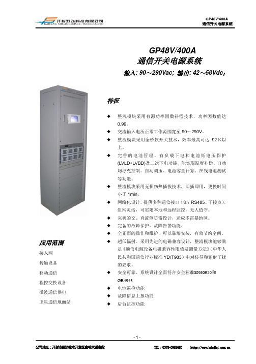
GP48V400A系统电源柜使用说明书
电池充电电流大于设定的电池最大充电电流时,系统对电池进行恒流均充,恒流均充到均充电压时,系统进行恒压均充,恒压均充电流小到均充转浮充电流以下时,电流浮充,浮充电流大于浮充转均充电流时,系统均充、浮充连续时间到设定时间则自动转均充,恒压均充时间超过设定均充持续时间,自动转浮充,手动均充则转均充。
严禁在雷雨天气下进行高压、交流电操作
2.2监控面板和端子说明17
2.3 LCD说明19
2.4环境及维护要求21
2.5触摸监控系统菜单树22
5.电气图27
1.系统概述
1.1GP48V/400A系统配置
GP48V/400A由机柜配电、整流模块(最少可配1个)、监控模块1个组成,具体选配模块可参考下表:
可选配置
9)控制器记录电池充放电的电压,电流,时间。可以根据电池充放电的曲线判断电池的好坏。
10)用户在现场能通过液晶显示和键区实地监控和更改设置/状态。
11)后台监控控制失效时,液晶显示的控制功能将被作为备用控制器工作。
12)控制器发送数据至上位机或远程监控中心。
13)用户可以通过电源监控软件来远程或本地更改系统设置或状态.(远程情况下最多允许255个基站,可扩展到65535个基站。)
监控系统提供给上位机一个RS485/232接口,上位机可远程对系统监控随时进行查询、设置和控制,实现“三遥”功能,通信时整个网络只选择其中一种接口作为通信方式,其中RS485组网用于1.2KM距离范围以内通信。
监控主要功能有:
a.向上位机发送监控单元实时的模拟数据;
b.向上位机发送监控单元实时的开关量数据;
输出效率
91
93
%
220Vac输入
保护
参数
- 1、下载文档前请自行甄别文档内容的完整性,平台不提供额外的编辑、内容补充、找答案等附加服务。
- 2、"仅部分预览"的文档,不可在线预览部分如存在完整性等问题,可反馈申请退款(可完整预览的文档不适用该条件!)。
- 3、如文档侵犯您的权益,请联系客服反馈,我们会尽快为您处理(人工客服工作时间:9:00-18:30)。
电池
危险
当心触电
进行电池作业之前,必须仔细阅读电池搬运的安全注意事项,以及电池的准确连接方法。 电池的不规范操作会造成危险。操作中必须严格注意、小心防范电池短路或电解液溢出、流失。电解液的溢出会对 设备构成潜在性的威胁,会腐蚀金属物体及电路板,造成设备损坏及电路板短路。 电池安装、操作前,为确保安全,应注意如下事项:
NetSure801 CA7 电源系统 用户手册
摘下手腕上的手表、手链、手镯、戒指等含有金属的物体。 使用专用绝缘工具。 使用眼睛保护装置,并做好预防措施。 使用橡胶手套,佩戴好预防电解液溢出的围裙。 电池在搬运过程中应始终保持电极正面向上,严禁倒置、倾斜。 电池安装好后,仔细检查电池与直流配电柜的极性连接是否正确,螺母是否拧紧。在电池连接好后,在电源系统通 电之前,应保证直流配电与电池的连接熔丝处于断开的状态,以免系统长期不上电造成电防止电击和能量危险,即使当 AC 输入电源被断开后,仍然有来自电池供电的危险导电部件。 电源电缆
注意
当心触电
在连接电缆之前,确认电缆、及电缆标签与实际安装是否相符。
NetSure801 CA7 电源系统 用户手册
工具
警告
当心触电
在进行高压、交流电各种操作时,必需使用专用工具,不得使用普通或自行携带的工具。 雷雨
危险
当心触电
严禁在雷雨天气下进行高压、交流电,及铁塔、桅杆作业。 在雷雨天气下,大气中会产生强电磁场。因此,为避免雷击损坏设备,要及时做好设备的良好接地。 静电
注意
人体产生的静电会损坏电路板上的静电敏感元器件,如大规模集成电路(IC)等。在接触设备,手拿插板、电路板、 IC 芯片等前,为防止人体静电损坏敏感元器件,必须佩戴防静电手腕,并将防静电手腕的另一端良好接地。 短路
NetSure801 CA7 电源系统 用户手册
安全注意事项
在开始操作之前,请仔细阅读操作指示、注意事项,以减少意外的发生。手册中的“小心、注意、警告、危险”事 项,并不代表所应遵守的所有安全事项,只作为各种操作安全注意事项的补充。因此,负责产品安装、操作的人员 必须经严格培训,掌握系统正确的操作方法及各种安全注意事项方可进行设备的各项操作。 在进行本公司产品、设备的各项操作时,必须遵守相关行业的安全规范,严格遵守由公司提供的相关设备注意事项 和特殊安全指示。
注意
信号线应与强电流或高压线分开绑扎,绑扎的间距至少为 150mm。
NetSure801 CA7 电源系统 用户手册
目
录
第一章 产品概述 ................................................................................................................................................................. 1 1.1 命名规则 .................................................................................................................................................................................1 1.2 简介.........................................................................................................................................................................................1 1.3 各组成部分简介 .....................................................................................................................................................................2 1.3.1 整流模块.....................................................................................................................................................................2 1.3.2 监控模块.....................................................................................................................................................................3 1.3.3 交流配电柜.................................................................................................................................................................3 1.3.4 直流配电柜.................................................................................................................................................................6 1.3.5 交直流合一柜...........................................................................................................................................................12 1.3.6 整流柜.......................................................................................................................................................................13 第二章 安装准备 ............................................................................................................................................................... 16 2.1 安装要求 ...............................................................................................................................................................................16 2.1.1 机房的环境要求 .......................................................................................................................................................16 2.1.2 机房的布置要求 .......................................................................................................................................................16 2.1.3 供电要求...................................................................................................................................................................17 2.1.4 安全防护要求...........................................................................................................................................................18 2.1.5 设备运行环境检测表 ...............................................................................................................................................19 2.2 贮存条件 ...............................................................................................................................................................................20 2.3 安装准备 ...............................................................................................................................................................................20 2.3.1 现场检查...................................................................................................................................................................20 2.3.2 工具与材料准备 .......................................................................................................................................................20 2.4 开箱验货 ...............................................................................................................................................................................22 第三章 安装 ...................................................................................................................................................................... 23 3.1 安装机柜 ...............................................................................................................................................................................23 3.1.1 在地板上安装...........................................................................................................................................................23 3.1.2 在支架上安装...........................................................................................................................................................24 3.1.3 机柜间连接...............................................................................................................................................................24 3.1.4 并机铜排连接...........................................................................................................................................................25 第四章 调试 ...................................................................................................................................................................... 26 4.1 调试注意事项 .......................................................................................................................................................................26 4.2 上电.......................................................................................................................................................................................26 4.3 设置基本参数 .......................................................................................................................................................................27