二次谐波抑制低通滤波器设计
408mhz的2次谐波3次谐波的抑制
408mhz的2次谐波3次谐波的抑制
摘要:
1.抑制2 次谐波和3 次谐波的背景和原因
2.408MHz 的2 次谐波和3 次谐波抑制的方法
3.抑制2 次谐波和3 次谐波的效果分析
4.总结
正文:
一、抑制2 次谐波和3 次谐波的背景和原因
在射频通信系统中,2 次谐波和3 次谐波的抑制一直是一个重要的课题。
因为在射频信号传输过程中,信号会受到各种干扰,其中2 次谐波和3 次谐波的干扰尤为严重。
如果不对这两种谐波进行抑制,将会严重影响通信系统的性能。
二、408MHz 的2 次谐波和3 次谐波抑制的方法
针对408MHz 的2 次谐波和3 次谐波的抑制,我们可以采取以下几种方法:
1.采用滤波器进行抑制。
滤波器可以有效地过滤掉2 次谐波和3 次谐波,从而保证信号的纯净度。
2.采用数字信号处理技术进行抑制。
通过数字信号处理技术,可以在接收端对信号进行处理,抑制2 次谐波和3 次谐波。
3.采用频率调制技术进行抑制。
通过调整信号的频率,使其与2 次谐波和3 次谐波的频率错开,从而达到抑制的效果。
三、抑制2 次谐波和3 次谐波的效果分析
以上三种方法对408MHz 的2 次谐波和3 次谐波的抑制效果都非常显著。
滤波器和数字信号处理技术可以有效地过滤掉2 次谐波和3 次谐波,而频率调制技术则可以从根本上避免2 次谐波和3 次谐波的干扰。
四、总结
408MHz 的2 次谐波和3 次谐波的抑制是射频通信系统中一个重要的课题。
二阶低通滤波器的设计要点

二阶低通滤波器的设计要点1.滤波器类型选择:二阶低通滤波器有许多不同的类型,包括巴特沃斯、切比雪夫、贝塞尔等。
根据实际需求选择合适的滤波器类型,以满足对于频率响应、阻带抑制等方面的要求。
2.滤波器参数选择:滤波器参数包括截止频率、阻带衰减等。
截止频率是指滤波器将信号截止的频率点,阻带衰减是指滤波器在截止频率之外的频段对信号的抑制程度。
需要根据实际应用需求选择合适的参数值,以保证所需的信号处理效果。
3.构建转移函数:根据选定的滤波器类型和参数,可以建立二阶低通滤波器的传递函数。
传递函数描述了滤波器对输入信号的响应特性,可以用于分析和设计滤波器。
4.滤波器电路实现:根据滤波器的传递函数,可以设计具体的电路实现。
常见的二阶低通滤波器电路包括RC电路、RLC电路等。
可以通过选择合适的电路拓扑和元件参数,来实现所需的滤波特性。
5.频率响应分析:设计完成后,需要进行频率响应分析,以确保滤波器的性能满足要求。
可以使用仿真工具或实验测量的方法,观察滤波器在不同频率下的响应特性。
若有需要,可以对设计参数进行调整以达到预期的性能。
6.稳定性和阻带波纹:稳定性是指滤波器的输出能否在有限时间内收敛到稳定的目标状态。
对于二阶低通滤波器,稳定性要求其传递函数的极点都位于左半平面,以保证系统的稳定性。
另外,阻带波纹是指滤波器在截止频率附近的振荡现象。
设计时需要注意减小阻带波纹的幅度,以确保输出信号的稳定性。
7.电路实现工艺:根据滤波器的实际应用场景,选择适当的电路实现工艺。
常见的工艺包括模拟电路实现、数字滤波器实现、集成电路实现等。
不同的工艺具有各自的优点和限制,需要根据实际情况选择适合的工艺。
8.优化设计:进行性能优化和设计改进。
可以通过参数调整、电路拓扑优化等方法来改进滤波器的性能。
此外,还可以使用自适应滤波、多级联结等技术来提高滤波器的性能。
总结起来,设计二阶低通滤波器需要考虑滤波器类型选择、参数选择、转移函数构建、电路实现、频率响应分析、稳定性和阻带波纹、电路实现工艺以及优化设计等要点。
二阶低通滤波器设计报告

二阶低通滤波器设计报告设计目标:设计一个二阶低通滤波器,实现对输入信号的高频成分进行抑制,从而实现信号的平滑处理。
设计原理:二阶低通滤波器是基于巴特沃斯(Butterworth)滤波器的设计方法。
巴特沃斯滤波器是一种特殊的滤波器,其特点是在通带范围内具有最平坦的幅频特性,且在阻带范围内具有最快的衰减。
设计步骤:1. 确定滤波器的通带截止频率和阻带截止频率。
通带截止频率是指在该频率之前的信号成分会通过滤波器,而在截止频率之后的信号成分会被滤波器抑制。
阻带截止频率是指在该频率之后的信号成分会被滤波器抑制。
2. 根据巴特沃斯滤波器的设计表格,可以得到二阶低通滤波器的主要参数:截止频率、通带增益和阻带衰减。
3. 根据所给的截止频率和阻带衰减要求,在设计表格中找到相应的参数值,并得到对应的通带增益。
4. 根据得到的参数值,可以计算出二阶低通滤波器中各个阶段的传递函数和巴特沃斯滤波器的极点位置。
5. 根据所得到的传递函数和极点位置,可以确定滤波器的系统函数。
6. 可以使用系统函数进行滤波器的频率响应仿真和频率响应曲线的绘制。
7. 根据设计需求,可以进行滤波器的进一步优化,如增加滤波器阶数或采用其他滤波器设计方法。
设计结果:根据给定的截止频率和阻带衰减要求,得到了二阶低通滤波器的参数值。
通过系统函数的频率响应仿真和绘制,可以验证滤波器的设计效果。
结论:二阶低通滤波器是一种常用的滤波器设计方法,可以实现对信号的高频成分进行抑制,从而实现信号的平滑处理。
通过合理选择滤波器的参数值,可以得到满足设计要求的滤波器。
在实际应用中,可以根据具体需求对滤波器进行进一步优化,以获得更好的滤波效果。
课程设计--二阶低通滤波器设计

课程设计--二阶低通滤波器设计1. 理论基础二阶低通滤波器(second-order low-pass filter)属于电子滤波器的一种。
在电子信号处理中,低通滤波器(low-pass filter)是指可以滤掉高频部分,只保留信号中低频部分的滤波器。
二阶低通滤波器可以更加有效的滤掉高频部分,有更好的频率响应特性。
2. 实验目的设计一个二阶低通滤波器,学习和掌握滤波器的设计方法和理论基础。
3. 实验器材- 电阻器- 电容器- 运放(OPAMP)4. 实验步骤步骤1:选择设定滤波器的截止频率fc,以及质量因数Q值。
其实这两个参数是相互影响的,如果截止频率增大,Q值也需要增大;如果Q值增大,则截止频率也需要增大。
具体选择需要根据实际需求和设计条件来确定。
步骤2:根据所选择参数,计算出滤波器的电路参数,包括电容器和电阻器的阻值和电容值。
步骤3:按照电路图进行电路连接和布线。
步骤4:进行实验测试。
可以使用信号发生器输入测试信号,观察输出信号波形和频率响应特性。
5. 实验结果根据实际需要和设计条件,选择合适的截止频率和Q值,设计出二阶低通滤波器电路,进行实验测试。
观察输出信号波形和频率响应特性。
6. 实验注意事项- 实验时需要注意硬件电路的连接问题;- 工作电压选择和滤波器电路的工作范围匹配;- 实验测试时需要合理地选择信号频率和振幅,避免过高的信号幅值造成硬件模块损坏,或者信号失真等问题。
7. 实验拓展- 可以进行滤波器级数的增加,设计更高阶的滤波器电路;- 可以修改电路参数和工作电压,观察滤波器的频率响应曲线变化;- 可以将低通滤波器改成高通滤波器、带通滤波器和带阻滤波器等,进行不同类型滤波器的设计。
有源电力滤波器重复控制方法的设计_许明夏
重复控制的基本思想源于内模原理。 内模原理 指把作用于系统的外部动力学模型嵌入控制器,构 成高补偿精度的反馈系统 [11]。
有源电力滤波器一般要求补偿 39 次基波频率 的谐波。 如果将这些次谐波模型都植入控制器,在 工程上不可行。 由于参考的信号是周期重复的信 号,于是通过在控制器中嵌入一个基波周期的延时 环节,实现误差信号的周期累加。 基波周期为 T 的 外部信号的内模为:
滤波器(APF)中,实现 PI 控制和重复控制的双闭环电流控制。 同时讨论了重复控制的稳定性和稳态误差,分析了重
复控制器的参数设计。 最后在一台 20 kVA 并联型有源电力滤波器样机上验证了该方法的使用性和有效性。
关键词:有源电力滤波器;重复控制;谐波畸变率
中 图 分 类 号 :TM344.1
文 献 标 志 码 :A
第2期 2012 年 3 月
电源学报 Journal of Power Supply
No.2 Mar.2012
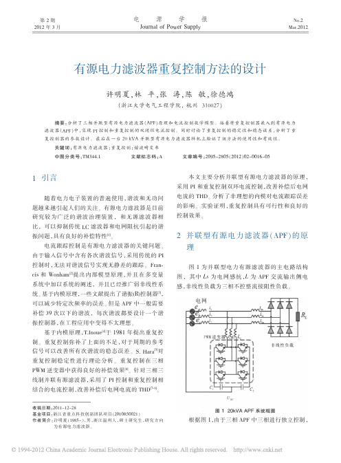
有源电力滤波器重复控制方法的设计
许明夏,林 平,张 涛,陈 敏,徐德鸿
(浙江大学电气工程学院, 杭州 310027)
摘要:分析了三相并联型有源电力滤波器(APF)原理和电流控制数学模型。 接着将重复控制器嵌入到有源电力
值 20 kVA 220 V(RMS) 15 kHz 0.05 mH 0.8 mH 2 200 μF 760 V
图 9 传统算法的实验波形
图 10 是 加 入 重 复 控 制 控 制 算 法 的 实 验 波 形 ,
20
电
源
可以看出补偿后的电网电流比较光滑。 系统在 40 kW 不 控 整 流 负 载 时 , 补 偿 后 的 电 网 电 流 THD 为 2.75%。
低通滤波器
EMI 滤波器设计原理高频开关电源由于其在体积、重量、功率密度、效率等方面的诸多优点,已 经被广泛地应用于工业、 国防、家电产品等各个领域。
在开关电源应用于交流电 网的场合,整流电路往往导致输入电流的断续, 这除了大大降低输入功率因数外, 还增加了大量高次谐波。
同时,开关电源中功率开关管的高速开关动作 (从几十 kHz 到数 MHz ),形成了 EMI ( electromagnetic interference )骚扰源。
从已发表的开关电源论文可知, 在开关电源中主要存在的干扰形式是传导干扰和近场 辐射干扰,传导干扰还会注入电网,干扰接入电网的其他设备。
减少传导干扰的方法有很多, 诸如合理铺设地线, 采取星型铺地, 避免环形 地线,尽可能减少公共阻抗;设计合理的缓冲电路;减少电路杂散电容等。
除此 之外,可以利用 EMI 滤波器衰减电网与开关电源对彼此的噪声干扰。
EMI 骚扰通常难以精确描述,滤波器的设计通常是通过反复迭代,计算制作 以求逐步逼近设计要求。
本文从 EMI 滤波原理入手, 分别通过对其共模和差模噪 声模型的分析,给出实际工作中设计滤波器的方法,并分步骤给出设计实例。
1 EMI 滤波器设计原理在开关电源中, 主要的 EMI 骚扰源是功率半导体器件开关动作产生的 dv/dt 和 di /d t ,因而电磁发射 EME (Electromagnetic Emission ) 通常是宽带的噪声信 号,其频率范围从开关工作频率到几 MHz 。
所以,传导型电磁环境( EME )的测 量,正如很多国际和国家标准所规定,频率范围在 0.15 ~30MHz 。
设计 EMI 滤波 器,就是要对开关频率及其高次谐波的噪声给予足够的衰减。
基于上述标准, 通 常情况下只要考虑将频率高于 150kHz 的 EME 衰减至合理范围内即可。
在数字信号处理领域普遍认同的低通滤波器概念同样适用于电力电子装置中。
宽带谐波抑制天线设计

宽带谐波抑制天线设计
殷玉凤;汪敏;徐诺;吴文
【期刊名称】《天线学报》
【年(卷),期】2017(006)001
【摘要】本文针对微波能量采集整流天线的应用,设计了一款宽带滤波天线。
该天线由C-CMRC低通滤波器和多层结构的U型缝微带天线组成。
首先通过加空气层和在贴片上加载U形缝隙展宽了天线的带宽,然后在馈线上加载低通滤波器对二次和三次谐波进行抑制。
天线的实测工作频率范围为2.2 GHz~2.6 GHz,相对带宽约为16%。
实测和仿真结果表明天线在二次和三次谐波频率处的回波损耗均小于1 dB。
【总页数】7页(P1-6)
【作者】殷玉凤;汪敏;徐诺;吴文
【作者单位】[1]南京理工大学JGMT国防重点学科实验室,江苏南京;;[1]南京理工大学JGMT国防重点学科实验室,江苏南京;;[1]南京理工大学JGMT国防重点学科实验室,江苏南京;;[1]南京理工大学JGMT国防重点学科实验室,江苏南京
【正文语种】中文
【中图分类】TN8
【相关文献】
1.5.8 GHz具有谐波抑制功能的天线设计 [J], 崔鹏;陈凯亚;廖成
2.具有谐波抑制功能的圆极化整流天线设计 [J], 蒋永祥;邹传云
3.一种具有谐波抑制功能的圆极化天线设计 [J], 李路;刘一麟;李君;黄卡玛;杨阳
4.一种具有谐波抑制功能的圆极化天线设计 [J], 李路;刘一麟;李君;黄卡玛;杨阳;;;;;
5.一种2.45GHz谐波抑制有源集成天线设计 [J], 刘露;刘长军
因版权原因,仅展示原文概要,查看原文内容请购买。
二阶压控型低通滤波器的设计

二阶压控型低通滤波器的设计一、二阶压控型低通滤波器的基本原理二阶低通滤波器通过减弱输入信号中高频部分的幅值,使得只有低频信号通过,可以实现信号的滤波功能。
压控型低通滤波器是通过改变其截止频率来实现对滤波频带的调节。
其基本原理是通过控制压控电阻或电容的阻值或容值来改变滤波器的截止频率。
压控型低通滤波器一般包括一个滤波电路和一个控制电路。
滤波电路实现信号的滤波功能,控制电路实现对滤波频带的调节。
二、二阶压控型低通滤波器的电路结构二阶压控型低通滤波器的电路结构一般包括一个滤波器电路和一个控制电路。
滤波器电路可以采用多种形式的RC电路,如T型电路、π型电路等。
其中,T型电路是一种常用的二阶低通滤波器电路,其具有较好的性能。
控制电路可以通过压控电阻或压控电容对滤波电路中的元件进行控制,从而实现对滤波频带的调节。
三、二阶压控型低通滤波器的参数选择在设计二阶压控型低通滤波器时,需要考虑的参数有滤波器的截止频率、增益和带宽。
其中,截止频率决定了滤波器的频率响应特性,增益决定了输出信号的幅值,带宽决定了滤波器的频带范围。
选择合适的截止频率是设计二阶压控型低通滤波器的关键。
一般情况下,截止频率的选择要根据滤波器应用的具体需求来确定。
如果需要滤除较高频率的噪声信号,截止频率应选择为噪声信号频率以上的其中一值。
如果需要保留较低频率的信号,截止频率应选择为需要保留的信号频率以下的其中一值。
增益和带宽的选择也需要根据具体应用需求来确定。
增益一般情况下选择为1,即不改变输入信号的幅值。
带宽则根据应用要求选择,要保证滤波器能够滤除高频噪声信号,同时保留所需的信号频率。
最后,要注意选择合适的元件参数来实现设计要求。
电阻和电容的选择需要考虑其阻值或容值与滤波器的截止频率的关系,以及其功率容量和可靠性等因素。
另外,在控制电路中,压控电阻或压控电容的选择需要考虑其控制范围和控制灵敏度等因素。
总结起来,二阶压控型低通滤波器的设计需要从基本原理、电路结构和参数选择三个方面进行考虑。
- 1、下载文档前请自行甄别文档内容的完整性,平台不提供额外的编辑、内容补充、找答案等附加服务。
- 2、"仅部分预览"的文档,不可在线预览部分如存在完整性等问题,可反馈申请退款(可完整预览的文档不适用该条件!)。
- 3、如文档侵犯您的权益,请联系客服反馈,我们会尽快为您处理(人工客服工作时间:9:00-18:30)。
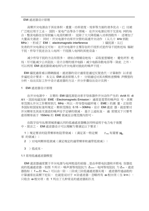
44February 1999IntroductionThe FCC requires transmitter spurious outputs below 30 MHz to be attenuated by 40 dB or more for power levels between 5 and 500 W (Ref 1). Radio amateurs usu-ally attempt to satisfy this requirement by placing a seven-element standard-value capacitor (SVC) low-pass filter (LPF) after the final amplifier. This procedure was dem-onstrated by Dave Benson, NN1G, in his QST article discussing a 3-W PEP QRP SSB transceiver for 20 or 75 meters (see Ref 2).The seven-element Chebyshev LPF is ad-equate for Benson’s application because spurious signals must be attenuated by only 30 dB at power levels less than 5 W.For power levels greater than 5 W,the typical second-harmonic attenuation (40-dB) of a seven-element Chebyshev LPF is marginal. An additional 10 dB of attenuation is needed to assure compliance with the FCC requirement (Ref 3).If the standard seven-element Cheby-shev SVC LPF could be slightly modified to obtain an additional 10 dB of stop-band loss at the second-harmonic frequency without significantly decreasing its passband return loss (RL), the problem would be solved.The minimum passband RL of Benson’s 20-meter LPF is about 21 dB, and this mini-mum RL level is suitable to use as a guide for an acceptable return loss after the filter design modifications have been completed.We can easily increase the 20-meter SVC LPF second-harmonic attenuation at 28 MHz by adding a capacitor across the cen-ter inductor to form a resonant circuit. If this is done, however, the 20-meter passband RL decreases to an unacceptable level, less than 12.5 dB. We need a way to add the resonant circuit, while maintaining an acceptable RL level over the 20-meter passband.The typical LPF used by Benson (and the Chebyshev SVC designs listed in TheSecond-Harmonic-Optimized Low-Pass FiltersSometimes we need a little more output filtering thantraditional designs offer. Look at a new filter that can give you that extra boost.Above: A QRP 20-meter CWAZ low-pass filter installed on a piece of perf board in a small (1×27/8×2-inch, HWD) plastic box available from Farnell (Ref 4), order #645-680, $1.56 each. The toroidal cores are Micrometals (Ref 5) T50-17. The capacitors shown are Philips 683 series, low-k, 100 V dc, with a 2% tolerance. Some of those shown have a 0.2-inch lead spacing, which is no longer available from Farnell. For new construction, use Philips 680, low-K series having 0.1-inch lead spacing. The Philips 680 series is good for all QRP filtering because of its 2% tolerance.Figure 1—Schematic diagram of a CWAZ low-pass filter designed for maximum second-harmonic attenuation. See Table 1 for component values of CWAZ 50-Ω designs. L4 and C4 are tuned to resonate at the F4 frequency given in Table 1. For an output power of 10 W into a 50-Ω load, the RMS output voltage is 1050224×=.V . Consequently, a the load SWR is less than 2.5:1. For QRP filtering, use Philips 680 low K (high Q), 100 Vdc ceramic capacitors, mainly for their close tolerance (2%). This capacitor is available from Farnell/Newark in values up to 330 pF and is listed on page 62 of the March/September 1998 Farnell catalog (Ref 4). For QRP filtering, the Micrometals T37, T44 or T50 cores of materials –2 (red), –6 (yellow) or –17 (blue/yellow) are suitable (Ref 5).These cores are available in small quantities from Amidon (Ref 6).ARRL Handbook ) all have maximum SWR (equivalent to a minimum RL level) specifi-cations that extend from the filter ripple-cutoff frequency down to dc. For the usual Amateur Radio application, however, we need an acceptable minimum RL only over the amateur band for which the LPF is de-signed. If the passband RL below the ama-teur band (where it is not needed) could be exchanged to improve the RL only in the passband—while simultaneously increasing the stop-band loss at the second-harmonic frequency—it would be practical to resonate the center inductor at the second harmonic.Our problem would be solved.This problem of significantly increas-ing the second-harmonic attenuation of the seven-element Chebyshev LPF while maintaining an acceptable RL over the amateur passband has been solved by Jim Tonne, WB6BLD. With Jim’s approval and encouragement, I am using this articleFebruary 199945Table 1CWAZ 50-Ω Low-Pass FiltersDesigned for second-harmonic attenuation in amateur bands below 30 MHz.StartBand Frequency C1,7C3,5C4L2,6L4F4(m)(MHz)(pF)(pF)(pF) (µH)(µH)(MHz)— 1.0029864556680.19.3778.516 2.09116592531378 3.761601.801450 + 2202100 + 470 5.214.731500 + 1502200 + 330330 + 47 3.7885313021947.3280 3.501150 + 150 2.68 2.43470 + 3901200 + 100150 + 477.2742765197.214.6407.00 1.34 1.22330 + 100330 + 33010014.429645167.321.13010.10.9280.843150 + 1504706821.021332548.629.32014.00.6700.6082203304729.816525237.637.81718.0680.5190.47182 + 82100 + 1503937.114221732.443.91521.00.4470.4061502203343.512018327.352.01224.890.3770.3421201802752.410716324.358.51028.00.3350.30410082 + 822755.6NOTE:as a means of describing this LPF design advancement for the benefit of the Ama-teur Radio fraternity.A New Type of Low-Pass FilterThis article introduces a new eight-element LPF having a topology similar to that of the seven-element Chebyshev LPF,with two exceptions: The center inductor is resonated at the second harmonic in the fil-ter stop band, and the component values are adjusted to maintain a more than accept-able RL across the amateur passband. To distinguish this new low-pass filter from the familiar SVC Chebyshev LPF, I pro-pose that this new filter be named the “Chebyshev with Added Zero” LPF or aThe CWAZ low-pass filters are designed for a single amateur band to provide more than 50 dB attenuation to the second harmonic of the fundamental frequency and to the higher harmonics. All component values for any particular band are calculated by dividing the 1-MHz values in the first row (included for reference only) by the start frequency of the selected band. The upper capacitor values in each row show the calculated design values obtained by dividing the 1-MHz capacitor values by the amateur-band start frequency in megahertz. The lower standard-capacitor values are suggested as a convenient way to realize the design values. The middle capacitor values in the 160- and 80-meter-band designs are suggested values when the high-value capacitors (greater than 1000 pF) are on the low side of their tolerance range. The design F4 frequency (see upper value in the F4 column) is calculated by multiplying the 1-MHz F4 value by the start frequency of the band. The lower number in the F4 column is the F4 frequency based on the suggested lower capacitor value and the listed L4 value.“CWAZ” LPF design. With this desig-nation, you should understand that these LPFs are output filters for single-band transmitters . They provide optimum sec-ond and higher harmonic attenuation while maintaining a suitable level of return loss over the amateur band for which they’re designed.Figure 1 shows a schematic diagram of a CWAZ LPF design. Table 1 lists suggested capacitor and inductor values for all ama-teur bands from 160 through 10 meters.These tabulated values were derived from the normalized values provided to me by Jim Tonne for use in this article. If you want to confirm my tabulated values or calculate the CWAZ values for different bands, sim-ply divide the first-row C and L values (for 1 MHz) by the start frequency of the desired band. For example, C1, 7 for the 160-meter design is equal to 2986/1.80 = 1659 pF. The other component values for the 160-meter LPF are calculated in a similar manner.CWAZ Versus Seventh-Order SVC ChebyshevThe easiest way to demonstrate the superi-ority of a CWAZ LPF over the Chebyshev LPF is to compare the RL and insertion-loss responses of these two designs. As an example of a Chebyshev design, we will use the 20-meter SVC LPF design used by NN1G for filtering the output of his 20-meter QRP SSB transceiver.Figure 2 shows the computer-calcu-lated return- and insertion-loss responses of a seven-element Chebyshev SVC LPF commonly used for attenuating the har-monics of a 20-meter RF amplifier. The plotted responses were made using Jim Tonne’s ELSIE filter design and analysis software. This DOS-based program is available from Trinity Software (Ref 7).The component values, obtained from the LPF schematic diagram shown in Figure 1on page 30 of NN1G’s QST article, were used by ELSIE in plotting the Chebyshev SVC LPF responses. A sketch of the filter topology with component values is in-cluded in Figure 2.Figure 3 shows the computer-calculated return- and insertion-loss responses of a CWAZ LPF intended to replace the seven-element 20-meter Chebyshev SVC LPF. The stop-band attenuation of the CWAZ LPF in the second-harmonic band is more than 60 dB and is substantially greater than that of the Chebyshev LPF. Also, the pass-band RL of the CWAZ LPF is quite satisfactory,at more than 25 dB. The disadvantages of the CWAZ design are that an extra capacitor is needed across L4, and several of the designs listed in Table 1 require paralleled capaci-tors to realize the design values. Neverthe-less, I believe these disadvantages are minor in comparison to the increased second-har-monic stop-band attenuation that is possible with a CWAZ design.LC Filter-Design Demo Software is AvailableThose involved in passive LC filter de-sign on an amateur and semiprofessional basis may experience the capabilities of ELSIE through a demo disk that is available from Jim Tonne. I use ELSIE V 1.11 with a 386SX CPU operating at 20 MHz. Although the plotting response of this computer is slow, I can evaluate the return- and inser-tion-loss responses of a design in less than 10 seconds, by using the minimum number of data points for preliminary plots. V 1.11requires less than 1 Mb of hard disk space,while a more recent V 1.23 requires about 1.1 Mb. ELSIE requires a hard disk.The ELSIE demo disk is restricted to LC filters of the third-order or less, but one can still explore all the capabilities of ELSIE in the design and analysis of filters. For ex-46February 1999ample, you can use the tune option to adjust the component values of a Cauer third-order band-pass filter until the trans-mission zeroes fall in the centers of the ad-jacent ham bands for optimum RF selectiv-ity. This would be impractical with tables of normalized values, but ELSIE can evalu-ate many different designs in a relatively short time.If you are seriously interested in passive LC filter design and analysis, but cannot afford the high-priced software used by professional filter designers, contact Jim Tonne at Trinity Software (see Ref 7) about the ELSIE demo disk.SummaryThe seven-element SVC Chebyshev low-pass filter is commonly used to attenuate the second and higher harmonics of QRP RF transmitters to comply with FCC require-ments. Using ELSIE, I’ve demonstrated that the second-harmonic attenuation provided by a seven-element Chebyshev SVC low-pass filter is marginal. I introduced a new filter that provides maximum attenuation at the second-harmonic frequency while simul-taneously maintaining an acceptable return loss in the filter pass band. This is accom-plished by forming a resonant circuit (the center inductor and capacitor) and using spe-cial values of inductance and capacitance to restore the passband return loss. A table of precalculated 50-ΩCWAZ LPF designs ispresented for all the amateur bands. I evalu-ated an example 20-meter CWAZ LPF de-sign to demonstrate how the harmonic at-tenuation is improved over that of a standard Chebyshev LPF while still maintaining an acceptable pass-band return loss.Whether or not these new CWAZ LPFs will eventually supersede the more famil-iar seven-element Chebyshev SVC LPFs remains to be seen. I encourage you to try these new CWAZ designs and report your experience with them.References1. Dean Straw, N6BV, Ed., 1998 ARRL Hand-book for Radio Amateurs , 75th Ed,(Newington: ARRL, 1997) Figure 29.3, p 29.7. (Because of WRC-97, new, more-strin-gent emission standards will take effect over the next few years. For details see Technical Correspondence (QST , Jun 1998, pp 61-62)and Larry E. Price, W4RA, and Paul Rinaldo,W4RI, “WRC-97—An Amateur Radio Per-spective,” QST , Feb 1998, pp 31-34.—Ed.)2. Dave Benson, NN1G, “A Single-Board QRP SSB Transceiver for 20 or 75 Meters,” QST ,Apr 1997, p 29.3. These filters are most useful with single-band, single device transmitters. Common medium-power multiband transceivers use push-pull power amplifiers because such amplifiers inherently suppress the second harmonic. This suppression then permits the use of octave-related low-pass filters (eg, 2,4, 8, 16 and 32 MHz) rather than a separate filter for each band.—Ed .4. Farnell Electronic Components Catalog ,copyright 1998 by Newark Electronics, Chi-cago, IL 60640; tel 800-718-1997, fax 800-718-1998; .5. Iron-powder cores catalog RF Applications,Issue F, Sep 1996. Micrometals, 5615 E La Palma Ave, Anaheim, CA 92807; tel 800-356-5977; .6. Amidon Associates, I nc, 240 Briggs Ave,Costa Mesa, CA 92626; tel 800-898-1883,fax 714-850-1163.7. Trinity Software, 7801 Rice Dr, Rowlett, TX 75088, (Jim Tonne, President); tel 972-475-7132.Ed Wetherhold, W3NQN, received a degree in Radio Engineering from Tri-State University,Angola, Indiana, in 1956. From 1962 to 1992, he was employed at the Annapolis Signal Analysis Center of Alliant Techsystems, Inc (Alliant Techsystems was formerly the Defense Division of Honeywell, Inc), as a communications systems test engineer and as a certified TEMPEST Pro-fessional Level II.Ed obtained his Amateur Radio license in 1947, while serving in the Air Force as a radio mechanic instructor at Scott AFB, in Illinois. For the past 22 years, he has been a technical advisor to the ARRL on passive LC filters. Ed’s many articles on simplified filter design have been pub-lished in the electronics trade and Amateur Ra-dio journals, such as Interference Technology Engineers’ Master (ITEM), QST , QEX , CQ and Practical Wireless , and in professional EMC journals. The 1998 ARRL Handbook contains Ed’s SVC filter design tables and an explanation of how to design passive LC filters.While not working on filters, Ed is active as a tournament tennis player and is ranked Number 1 in the Men’s 70 doubles in the USTA’s Middle Atlantic section. You can contact Ed at 1426268-0916, fax 410-268-4779.and insertion-loss responses of the seventh-order Chebyshev SVC low-pass filter used in the April 1997 QST article toattenuate second-harmonic signals. The 20-meter passband RL is about 21 dB, and the insertion loss over the second-harmonic frequency band ranges from 35 to 39 dB. A listing of the component values is included.Figure 3—The plots show the ELSIE computer-calculated return-and insertion-loss responses of the eight-element low-pass filter using the CWAZ capacitor and inductor values listed in Table 1for the 20-meter low-pass filter. Notice that the calculated attenuation to second-harmonic signals is greater than 60 dB,while RL over the 20-meter passband is greater than 25 dB.。