AWP-2000F防水涂料及同步千斤顶
反恐精英AWP使用技巧

反恐精英AWP使用技巧
Amanda
【期刊名称】《家庭电脑世界》
【年(卷),期】2003(000)006
【摘要】这回我们讨论的话题还是CS中著名的武器AWP(B46),以前我们已经讨论过AWP的用法,这次就AWP在使用上的一些小技巧,或是一些你不知道的小窍门来做个大讨论。
因此.就算你是AWP的使用高手.也不要错过我们的这次大讨论.它将使你更加全面地了解你手中这把CS中攻击力最强大的武器。
【总页数】2页(P154-155)
【作者】Amanda
【作者单位】无
【正文语种】中文
【中图分类】TS952.83
【相关文献】
1.旭化成AWP水洗版r使印刷更具可持续性和高效性 [J], Niederstadt
2.AWP-2000F型纤维增强桥面粘结防水涂料在南京长江第四大桥的应用 [J], 陈君;陈健;陈根香
3.学术高度与教学宽度的务实融合--新加坡南洋艺术学院“AWP”教学模式的解读与分析 [J], 潘端伟
4.清洁转移之“缤映”版及水洗版AWP介绍 [J], 陈丽莎
5.距离-多普勒-频带域3D-AWP-MRF分类辅助的SARGMTI杂波抑制方法 [J], 韩超垒;杨志伟;张庆君;廖桂生;何鹏远
因版权原因,仅展示原文概要,查看原文内容请购买。
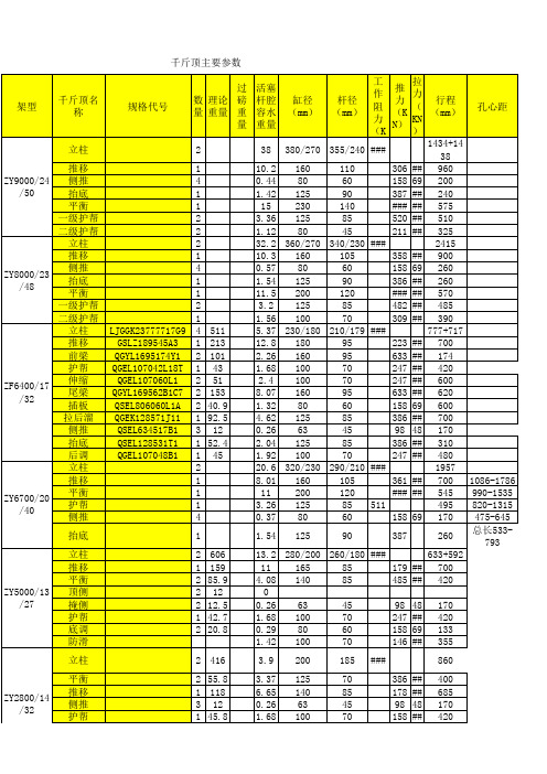
千斤顶总成参数
2415
105
358 ## 900
60
158 69 260
90
386 ## 260
120
### ## 570
85
482 ## 485
70
309 ## 390
210/179 ###
777+717
95
223 ## 700
95
633 ## 174
70
247 ## 420
70
247 ## 600
95
Hale Waihona Puke 633 ## 62060
600
1 79
125
70
700
1 41
110
85
250
鼓型圈(聚氨 酯)
o型密封圈 (P229橡
胶)
挡圈(聚四氟 乙烯)
o型密封 圈
(P229 橡胶)
挡圈(聚四 氟乙烯)
o型密 封圈 (P229 橡胶)
挡圈 (聚 四氟 乙 烯)
内蕾型圈(聚 氨酯)
挡圈(聚四氟乙 烯)
G160*135*38 G80*64*28 G125*10*12 G200*175*38 G125*10*12 G100*80*34
700 412 170 140
1220
750 345 170 507\500
597\583 750 170
1773(90 8+865)
570
170
700
ZF6000\17 \35放顶煤 (永新煤
矿)
护帮 尾梁 插板 拉后溜 抬底
1 55.7
100
70
470
2 148
160
105
520
AWP-2000F纤维增强型防水层的施工应用

AWP-2000F纤维增强型防水层的施工应用摘要:AWP-2000F纤维增强型防水材料具有优异的防水性,具有较高的抗拉强度、抗剪切能力和抗变形能力,能承受荷载的冲击、结构变形和机械设备的抗碾压能力,提高了沥青层与桥面之间的粘结强度,能够有效的提高桥面面层的适用寿命。
关键词:纤维增强型防水层;桥面防水;应用1 AWP-2000F纤维增强型防水层的类型及特点纤维增强型柔性防水涂层是指在柔性防水材料中掺入了纤维增强胎基而形成的防水层,首先具备一定的抗损伤性,因为机械设备在施工的过程中经常需要来回碾压防水层,因此,如果防水层不具备碾压的功能,就无法保证桥面的质量。
其次,还具备一定的粘结性和抗剪切能力,防水层处于混凝土与沥青混凝土之间,其具有很好的粘结性能,将沥青混凝土与水泥混凝土粘结成统一整体。
第三,具有优异的耐热性能,在设定的沥青混凝土摊铺温度下,保证其组成与性能不会变化。
第四,可以进行便捷的施工,冷施工作业,机械化,自动化程度高。
第五,纤维增强型防水材料抗老化性能好。
2 AWP-2000F纤维增强型防水材料的技术要求2.1纤维增强型防水涂料是通过在聚合物改性沥青与桥面粘结防水涂料中加入无捻粗纱,与涂料施工时同步切割混合喷涂,使得在防水层中间形成一层纤维均匀的与聚合物改性沥青形成的胎基,这样经过增强的聚合物改性沥青防水材料,通过同步切割工艺混合纤维材料进行喷涂,提高了沥青层与桥面之间的粘结强度,以及整体防水层的抗剪切强度,提高了防水涂层的抗裂和抗拉能力,提升了整体的防水效果。
能够有效的提高桥面面层的适用寿命。
成品检测要求见表1。
2.2 AWP-2000F纤维增强桥面粘结防水材料技术指标分别基于以下现行规范提出,并在相关重要指标上有所提升。
1)中华人民共和国建材行标准《道桥用防水涂料》(JC/T975-2005);2)中华人民共和国交通行业标准《路桥用水性沥青基防水涂料》(JTG535-2004)。
2.3纤维材料技术指标3 AWP-2000F纤维增强型防水层施工工艺3.1施工流程基面抛丸除渣处理—吹风除尘—重点部位处理—喷洒第一遍防水层—养生—喷洒第二层纤维增强防水层—养生—喷洒第三层纤维增强防水层—封闭交通3.2基面清理要求1)基面表面应压实平整,必须充分养护,不得有酥松、起砂、起皮、浮浆现象,应符合设计要求。
涂料工程施工机具(3篇)
第1篇一、涂料搅拌机涂料搅拌机主要用于混合涂料,使涂料中的固体颗粒均匀分散。
根据搅拌方式的不同,可分为电动搅拌机和手动搅拌机。
电动搅拌机具有操作简便、搅拌效率高、搅拌均匀等优点,适用于大型涂料施工;手动搅拌机则适用于小批量、小面积涂料施工。
二、涂料喷枪涂料喷枪是涂料施工中常用的工具,它可以将涂料均匀地喷涂到基面上。
根据喷涂方式的不同,可分为无气喷涂和有气喷涂。
无气喷涂适用于大面积、厚涂层的施工,具有速度快、效率高、涂膜质量好等优点;有气喷涂适用于小面积、薄涂层的施工,具有施工方便、涂膜均匀等优点。
三、滚筒滚筒是涂料施工中常用的工具,适用于大面积、厚涂层的施工。
滚筒可分为羊毛滚筒、尼龙滚筒、橡胶滚筒等。
羊毛滚筒适用于涂料的滚涂施工,涂膜均匀、手感细腻;尼龙滚筒适用于涂料和乳胶漆的滚涂施工,耐磨性好;橡胶滚筒适用于涂料的滚涂施工,具有良好的弹性和粘附性。
四、刷子刷子是涂料施工中常用的工具,适用于小面积、薄涂层的施工。
根据刷毛材质的不同,可分为猪鬃刷、羊毛刷、尼龙刷等。
猪鬃刷适用于涂料和乳胶漆的刷涂施工,涂膜均匀、手感细腻;羊毛刷适用于涂料和乳胶漆的刷涂施工,具有良好的弹性和粘附性;尼龙刷适用于涂料和乳胶漆的刷涂施工,耐磨性好。
五、刮刀刮刀是涂料施工中常用的工具,适用于填补、刮平、抹平等工作。
刮刀可分为塑料刮刀、金属刮刀等。
塑料刮刀适用于填补和刮平,具有施工方便、耐用等优点;金属刮刀适用于填补和刮平,具有施工方便、耐磨等优点。
六、刷毛整理器刷毛整理器是涂料施工中用于整理刷毛的工具,可保持刷毛的整齐和清洁,提高涂料施工质量。
七、涂料输送泵涂料输送泵用于将涂料从涂料桶中输送到施工地点,适用于大面积、厚涂层的施工。
涂料输送泵可分为电动输送泵和手动输送泵,电动输送泵具有输送效率高、操作简便等优点。
八、涂料量杯涂料量杯用于测量涂料用量,确保涂料施工的均匀性。
总之,涂料工程施工机具的选择和使用对涂料施工质量具有重要影响。
拓力 2000 POWERLIFT 2000 履带起重机参数表说明书

POWERLIFT2000·拓力200070t capacity · 70t 起重能力Crawler Crane履带起重机DATASHEET METRIC参数表(公制)POWERLIFT2000拓力2000国内同级别唯一采用扳起架型式,组装极为简化,47POWERLIFT 2000拓力2000MAIN BOOM CONFIGURATIONS · 主臂的配置Weights · 重量T otal weight incl. counterweight 21.6 t, 12 m H boom and hook block 总重量包括21.6吨的配重、12 m 的H 起重臂和吊钩66 tSuperstructure (with three drums, gantry, boom foot and boom backstops)上车(带有三个卷扬、扳起架、主臂根和主臂防后倾)17.9 tCar body 车体7.8 tCrawlers with standard drive 履带带有标准驱动器17.3 tCounterweight 配重21.6 tGround pressure · 接地比压Ground pressure, based on 66t total weight 基于66吨总重时的接地比压7.3 N/cm 2View thousands of Crane Specifications on 技术描述底盘底盘由三部分组成,车体和两个履带。
车体和履带间由液压油缸连接,以减少运输宽度。
车身箱型结构抗弯、抗扭,由结构钢焊接制造。
履带履带架:由抗弯结构钢焊接制成。
履带板、从动轮和驱动轮均由高强度热处理铸钢制造。
在每边有10个经表面硬化处理过的支重轮。
传动系斜轴式柱塞定量/变量马达。
贴面安装插装式双向制动阀,并带有制动释放阀。
制动器释放阀可以根据主油路压力自动打开制动器,简化操作步骤。
791-6620D 10吨空气 油漆服务杆说明书

Model # 791-6620 d10 TON AIR/HYDRAULICSERVICE JACKWARNINGBEFORE USING THIS DEVICE, READ THIS MANUAL COMPLETELY AND THOROUGHLY, UNDERSTAND ITS OPERATINGPROCEDURES, SAFETY WARNINGS AND MAINTENANCE REQUIREMENTS.It is the responsibility of the device owner to make sure all personnel read this manual prior to using the device. It is also the responsibility of the device owner to keep this manual intact and in a convenient location for all to see and read. If the manual or product labels are lost or not legible, contact NAPA for replacements. If the operator is not fluent in English, the product and safety instructions shall be read to and discussed with the operator in the operator's native language by the purchaser/owner or his designee, making sure that the operator comprehends its contents.This is the safety alert symbol. It is used to alert you to potential personal injury hazards. Obey all safety messages that follow this symbol to avoid possible injury or death.IMPORTANT: READ THESE INSTRUCTIONS BEFORE OPERATINGBEFORE USING THIS DEVICE, READ THIS MANUAL COMPLETELY AND THOROUGHLY, UNDERSTAND ITS OPERATING PROCEDURES, SAFETY WARNINGS AND MAINTENANCE REQUIREMENTS.It is the responsibility of the owner to make sure all personnel read this manual prior to using the device. It is also the responsiblity of the device owner to keep this manual intact and in a convenient location for all to see and read. If the manual or product labels are lost or not legible, contact NAPA for replacements. If the operator is not fluent in English, the product and safety instructions shall be read to and discussed with the operator in the operator's native language by the purchaser/owner or his designee, making sure that the operator comprehends its contents.THE NATURE OF HAZARDOUS SITUATIONSThe use of Portable Automotive Lifting Devices are subject to certain hazards that cannot be prevented by mechanical means, but only by the exercise of intelligence, care, and common sense. It is essential to have personnel involved in the use and operation of the device who are careful, competent, trained, and qualified in the safe operation of the device and its proper use when servicing motor vehicles and their components. Examples of hazards are dropping, tipping or slipping of loads caused primarily by improperly securing loads, overloading, off-centered loads, use on other than hard level surfaces, and using equipment for a purpose for which it was not intended.METHODS TO AVOID HAZARDOUS SITUATIONS• Read, study, understand and follow all instructions before operating this device.• Inspect the jack before each use. Do not use jack if damaged, altered, modified, in poor condition, leaking hydraulic fluid, or unstable due to loose or missing hardware or parts. Make corrections before using. • Lift only on areas of the vehicle as specified by the vehicle manufacturer. • Wear eye protection that meets ANSI Z87.1 and OSHA standards. • Do not use jack beyond its rated capacity.• This is a lifting device only. Immediately after lifting, support the vehicle with jack stands capable of sustaining the load before working on the vehicle.• Use only on a hard level surface free from obstructions so the jack is free to reposition itself during lifting and lowering operations. • Center load on saddle. Be sure setup is stable before working on vehicle. • Do not move or dolly the vehicle while on the jack.• Do not use saddle adapters or saddle extenders between the stock lifting saddle and the load. • Do not use any adapters unless approved or supplied by NAPA. • Always lower the jack slowly and carefully.• This product contains one or more chemicals known to the State of California to cause cancer and birth defects or other reproductive harm. Wash hands thoroughly after handling.•Failure to heed these warnings may result in serious or fatal personal injury and/or property damage.CONSEQUENCES OF NOT AVOIDING HAZARDOUS SITUATIONSFailure to read this manual completely and thoroughly, failure to understand its OPERATING INSTRUCTIONS, SAFETY WARNINGS,MAINTENANCE INSTRUCTIONS and comply with them, and failure to comply with the METHODS TO AVOID HAZARDOUS SITUATIONS could cause accidents resulting in serious or fatal personal injury and/or property damage.WARNING: Indicates a hazardous situation which, if not avoided, could result in death or serious injury.SETUPPLEASE REFER TO THE EXPLODED VIEW DRAWING IN THIS MANUAL IN ORDER TO IDENTIFY PARTS.1. In order to install the handle assembly item #58 in the handle socket item #36, first align the main handle tube with the largest hole in thehandle socket and the lock pin rod with the smaller hole in the handle socket.2. Make sure the lock pin rod is in the down/lock position before insertion in the handle socket. Once the main handle tube and lock pin rodare aligned with their respective holes in the handle socket, push the handle assembly in the handle socket so the end of the handle tube engages the release valve mechanism in the bottom of the handle socket and the lock pin rod engages one of the three (3) locking holes in the item #1 frame.3. Disengage the lock pin rod by pulling up on the lever and engaging the lever with the slot in top of the handle assembly. The handleassembly should be free to pump up and down.4. In order to check for proper handle assembly alignment with the handle socket, see if the lock pin rod will engage with the three lockingholes in the frame. Also, turn the release valve knob at the top of the handle assembly left and then right to see if the release valve u-joint in front and below the handle socket is rotating simultaneously with the turning of the knob.5. Before Use: Air may become trapped in the hydraulic system resulting in insufficient pump stroke, spongy pump feeling or inability topump lift arm to maximum height. Follow the air purging instructions below:STEP 1a. With the release valve knob in the closed position, turn the knob in a counterclockwise direction 2 to 3 complete revolutions.b. Depress the foot pedal 15 to 20 times.STEP 2a. Close the release valve knob by turning it in a clockwise direction until it stops.b. Depress the air valve lever 6 to 8 successive times and hold it down on the last depression. If the jack's lift arm will not raise, repeatsteps 1 and 2 again.c. If depressing the air valve will not raise the lift arm, follow step 3.STEP 3a. Close the release valve knob by turning it clockwise until it stops. Depress the foot pedal to raise the lift arm to its maximum height.b. Depress the air valve while simultaneously turning the release valve 2 to 3 revolutions in a counterclockwise direction. The lift armshould lower rapidly.c. Close the release valve knob by turning it clockwise until it stops. Depress the air valve to see if lift arm will raise. If not, repeat step 3several times to achieve maximum performance.STEP 4If the jack's lift arm will not raise by depressing the air valve, apply 4 to 5 drops of pneumatic oil in the end of the valve's quick-disconnect nipple, reattach the air line and repeat step 2. NOTE: The pneumatic oil may temporarily mist out from the airmotor's vent, but this is normal and should not be considered a leak.OPERATING INSTRUCTIONSThis is the safety alert symbol used for the OPERATING INSTRUCTIONS section of this manual to alert you to potentialpersonal injury hazards. Obey all instructions to avoid possible injury or death. IMPORTANT: Before attempting to raiseany vehicle, check vehicle service manual for recommended lifting surfaces.OPERATION:1. To raise load: Turn the knob at the top of the handle assembly in a clockwise direction until tight. . Position the jack under theload. Proceed to pump the handle in order to raise the lift arm to the load. As the saddle at the end of the lift arm gets closer tothe load, reposition the jack so the saddle will contact the load firmly and the load is centered on the saddle. Make sure thesaddle is correctly positioned. Raise the load to the desired work height. Place jack stands of appropriate capacity at the vehiclemanufacturers's recommended support areas that provide stable support for the raised vehicle. DO NOT CRAWL UNDERVEHICLE WHILE LIFTING VEHICLE OR PLACING OR REMOVING THE JACK STANDS! Once jack stands are positioned,turn the jack handle VERY SLOWLY in a counterclockwise direction to lower the load to rest on the jack stands. Inspect therelationship between the jack stands and load to make sure the setup is stable and safe. If the setup is not stable or safe, followthe preceding steps until corrected.2. To lower load: Follow the procedures mentioned in "To raise load" section of the OPERATING INSTRUCTIONS in order to raisethe load off the jack stands. Once the load has cleared the jack stands, remove the jack stands from under the load and awayfrom the work area. Turn handle very slowly in a counterclockwise direction until the load is completely lowered to the ground.Once the jack's lifting saddle has cleared the load, remove the jack from under the load. CAUTION: Keep hands and feet awayfrom the hinge mechanism of the jack.PREVENTATIVE MAINTENANCEThis is the safety alert symbol used for the PREVENTATIVE MAINTENANCE section of this manual to alert you to potentialpersonal injury hazards. Obey all instructions to avoid possible injury or death.IMPORTANT: The number one cause of jack failure in air/hydraulic jacks is dirt and moisture in the air motor and/or hydraulic system.The shop air supply should be equipped with water and dirt filter traps that should be emptied or cleaned according to a monthly maintenance schedule. An in line oil lubricator will extend the life of air/hydraulic jacks. Inoperable jacks caused by poorly equipped or maintained shop air systems are not eligible for warranty consideration. Contaminants can also enter the air/hydraulic system whenthe shop air line is disconnected from the jack air line and the line is dropped on the floor. Contaminants in the air couplers, once reconnected, will be driven into the system.WARRANTYPlease contact your local NAPA Auto Parts Store for details on warranty.PREVENTATIVE MAINTENANCE (CONT.)1. Always store the jack in a well protected area where it will not be exposed to inclement weather, corrosive vapors, abrasive dust, or any other harmful elements. The jack must be cleaned of water, snow, sand or grit before using.2. The jack must be lubricated periodically in order to prevent premature wearing of parts. A general purpose grease must beapplied to all zerk grease fittings, caster wheels, front axle wheels, elevator arm, handle base pivot bolts, release mechanism andall other bearing surfaces.IMPORTANT: Any jack found to be defective as a result of worn parts due to lack of lubrication or air/hydraulic system contaminated with water, rust and/or foreign materials from the air supply or other outside source is not eligible for warranty consideration.3. It should not be necessary to refill or top off the reservoir with hydraulic fluid unless there is an external leak. An external leak requires immediate repair which must be performed in a dirt-free environment by an authorized service center.IMPORTANT: In order to prevent seal damage and jack failure, never use alcohol, hydraulic brake fluid or transmission oil in the jack.4. Every jack owner is responsible for keeping the jack labels clean and readable. Use a mild soap solution to wash external sur faces of the jack but not any moving hydraulic components.5. Inspect the jack before each use. Do not use the jack if any component is cracked, broken, bent, shows sign of damage or leaks hydraulic fluid. Do not use the jack if it has loose or missing hardware or components, or is modified in any way. Take corrective action before using the jack again.6.Any hydraulic repairs within the warranty period must be performed by an authorized service center.TROUBLESHOOTINGRS6620B41 Complete Handle Assembly58RS6620DA Air Motor Assembly641 Frame 1 2Washer4 3 RS660903BL Front Wheel (incl. #2, 3, 3-1, 4,5) 2 3-1 RS660903A Roller Bearing Set 2 4 Snap Ring 25 Grease Fitting 56 Rod Link 2 7Bolt 2 8 RS660908Y Saddle 1 9 Lock Washer 2 10 Nut 2 11 Spring 1 12 Bolt 1 13 Bolt2 14 Snap Ring 2 15 Shaft 1 16 Washer 2 17 Ring 2 18Nut2 19 RS660916BL Rear Wheel Assembly2 20 RS660917 Caster Bolt Kit Assembly - incl. #20 (2), 21 (2) 2 21 Washer 4 22 Washer 4 23 Bolt4 24 Snap Ring 2 25 Shaft 1 26 Washer 1 27 Pin 1 28ALink Assy. 1 29 RS660929 Spring1 30RS550510Snap Ring -12 mm Diameter21 * Snap ring 12 * Washer 23 * O-ring 14 Piston Rod 15 * Piston ring 16 * Sealing washer 17 * O-ring 18 * O-ring Retainer 19 * Snap ring1 10 Oil cylinder assembly 1 11 * Oil Filler Plug2 12 * Steel ball 1 13 * Ball seat 1 14 * Spring 1 15 Screw1 16 * Sealing washer 1 17 Bolt 1 18 * Steel ball1 19*Copper washer132 **Copper washer 2 33 RS6620BA33 Oil valve assembly 1 34 ** Nylon Gasket 1 35 Pump cylinder 1 36 ** Oil seat1 37 ** Nylon Gasket 1 38 ** Copper washer 1 39 Nut 1 40 Bolt 8 41 Front cover 1 42 ** Steel Ball34 43 Air Pump Housing 1 44 Nut 1 45 Spring 1 46 Washer1 47 Cylinder Pump Plunger 1 48Piston Body "A"131 RS550509Pedal Pin 1 32 Pin Revision D 1 33 Pin1 35Cover Board 1 36 RS660932BL Handle Socket 1 37 RS550511BL Pedal 1 38 Nut 1 39Washer1 40 RS550535 Bolt Kit (Incl. 38, 39, 40) 1 41 Handle 1 42Sleeve2 43 RS660939Y Knob (incl. 43, 44) 1 44 Pin1 45 Control Rod 1 46 Spring 1 47 Washer2 48 Screw 2 49 Rod Joint 1 50Spring1 51 RS6614A51 Release Assembly Revision D 1 52 Convey Rod 1 53 Washer 1 54 Pin 2 55 Pin 1 56 Washer 1 57Ring2 58 RS6620B41 Complete Handle Assembly (incl. 41-49, 52-56) 1 59 RS6620D59 Complete Hydraulic Assembly Revision D 1RS6620DLKProduct Label Kit (not shown) Revision D1Index No. Part No. descriptionQty.Index No. Part No.description Qty.Index No. Part No.description Qty.Index No. Part No.descriptionQty.Index No. Part No. description Qty.Index No. Part No. descriptionQty.Parts list for HYDraUliC UNit: rs6620D59Parts list for air motor: rs6620Da20 Bolt 1 21 * Steel ball 1 22 * O-ring 1 23 *O-ring1 24 RS6620D24 Release valve Rod Revision D 1 29 * O-ring2 30 * Washer2 31 Cylinder Pump Plunger 1 A Screw 1 B * Copper washer 1 C * Spring 1 D * Steel Ball 9 1 E * Steel Ball 6 1 F Oil box 1 G Screw 1 H * Washer 1 I * Washer 1 JNut2 KRS6614AKHose (incl. J, K (2))149 ** O-ring 2 50 Air Release Rod 1 51 ** O-ring 2 52 Piston Body "B" 1 53 Bolt 3 54 Air Seal Revision D 1 55 ** O-ring 2 56 ** O-ring 1 57 Rear cover 1 58 pin 1 59 ** O-ring 2 60 screw 1 61 RS6620B61 Air valve (excluding hose) 1 62 O-ring 3 63 ** Nylon washer 2 64 RS6620DA Air Motor Assembly Revision D 1 65 RS6620B65 Hose 1Only index numbers identified by Part Number are available separately. * Only available in hydraulic repair kit RS6620DHRK. ** Only available in air motor repair kit RS6620DARK.。
AWP-2000F型纤维增强桥面粘结防水层在新九曲河大桥的应用

AWP-2000F型纤维增强桥面粘结防水层在新九曲河大桥的应用中图分类号: u445文献标识码:a文章编号:前言泰州长江大桥位于江苏省的泰州市和镇江、常州市之间,东距江阴长江公路大桥57公里,西距润扬长江公路大桥66公里,是江苏省“五纵九横五联”高速公路网和国家《长江三角洲地区现代化公路水路交通规划纲要》中的重要组成部分,也是江苏省规划建设的11座公路过江通道之一。
新九曲河大桥位于镇江丹阳市后巷镇境内,属于泰州长江公路大桥南接线镇江段g03标工程项目,跨越太平河、迎风河、新九曲河、中心河四条河流,桥梁全长2513.612m,桥梁起点桩号k46+116.505,终点桩号k48+630.117,设计汽车荷载等级:公路-i级,桥面净宽:2×净15.25m,采用六车道高速公路标准,设计速度为120km/h,预留八车道建设条件。
随着交通量和重型车辆的增加,桥面铺装因粘结和防水问题引起的桥面铺装层早期损坏,已成为影响桥梁美观、使用功能的发挥和诱发交通事故的一大病害。
近年来,人们越来越重视因桥面铺装粘结防水问题造成的病害。
为此,桥面防水在大跨径重大型桥梁铺装体系中的重要性越来越显突出。
新九曲河大桥桥面防水体系经过优化,并经过专家讨论,最终确立了采用基面抛丸清理工艺及纤维增强型防水层。
本文以新九曲河大桥为例,着重介绍纤维增强型防水体系的应用。
1.防水层的性能要求桥面防水是一个整体系统,包括防水层与排水设施以及其上的路面结构所组成,防水层的性能实际是取决于防水系统中各组成部分的互相作用,如因层间粘结性能及层间抗剪性能不足而导致防水层的破坏,那么即使防水层的性能完好,防水系统也将失去作用。
混凝土桥面柔性铺装结构设置完整的粘结防水系统能解决因层间粘结不良引起的桥面铺装层早期损坏问题和因桥面渗水而引起的美观问题和桥梁的结构破坏。
因此,理想的桥面防水层必须满足下列要求:(1)防水层必须是不透水的,包括在施工中的渗水和使用年限内的渗水;(2)防水层应与面层和桥面有足够的粘结力;(3)防水膜应能抵抗桥面裂缝,包括在施工前后所产生与发展的裂缝。
防水层施工中的施工工具与材料
防水层施工中的施工工具与材料防水层施工是建筑工程中非常重要的一环,它能够有效地防止水的渗透和漏水问题。
在进行防水层施工时,选择适当的施工工具和材料至关重要,本文将介绍一些常用的施工工具和材料,以及它们的特点和应用。
一、施工工具1. 刮板:刮板是进行防水层涂抹的常用工具之一。
通常由钢制或塑料制成,刮板的平整度和坚硬度对于施工质量有着直接的影响。
刮板的尺寸和形状应根据实际施工需要来选择,以确保涂层均匀且光滑。
2. 刷子:刷子也是施工中常用的工具之一。
刷子的材质多种多样,如天然毛刷、合成刷毛等。
根据施工需要,可以选择不同硬度和尺寸的刷子,以保证施工过程中能够有效地涂抹防水材料。
3. 滚筒:滚筒是较大面积施工时常用的工具。
它由中空管或芯筒和滚桶组成,能够均匀地涂抹防水材料。
滚筒的选择要考虑其柔软度、吸水性和耐用性等因素,以确保施工效果和质量。
4. 尺子和水平仪:在防水层施工中,尺子和水平仪是必不可少的工具。
尺子用于测量涂层的厚度和长度,水平仪用于保证涂层的水平度。
正确使用尺子和水平仪可以有效提高施工质量,避免出现施工偏差。
二、施工材料1. 防水涂料:防水涂料是防水层施工中常用的材料之一。
它具有良好的附着力和抗渗透能力,能够形成坚固的防水膜。
防水涂料的种类繁多,如聚合物涂料、双组分涂料等,根据实际需求选择合适的材料进行施工。
2. 防水卷材:防水卷材是一种以聚合物高分子材料为主体的柔性卷材。
它通常由底材、面材和防水层组成,能够有效地防止水分渗透。
防水卷材具有较高的抗拉强度和耐候性,适用于多种建筑结构的防水施工。
3. 防水胶粘剂:防水胶粘剂是将防水卷材固定在建筑结构上的常用材料。
它具有良好的粘附性和耐候性,能够确保防水卷材与建筑结构紧密粘合,并形成稳固的防水膜。
4. 防水填缝剂:防水填缝剂用于处理防水层施工中的接头和缝隙。
它具有较高的弹性和抗老化能力,能够有效地防止水分渗透。
根据不同的施工要求,可以选择硅酮类、聚氨酯类等不同类型的防水填缝剂。
- 1、下载文档前请自行甄别文档内容的完整性,平台不提供额外的编辑、内容补充、找答案等附加服务。
- 2、"仅部分预览"的文档,不可在线预览部分如存在完整性等问题,可反馈申请退款(可完整预览的文档不适用该条件!)。
- 3、如文档侵犯您的权益,请联系客服反馈,我们会尽快为您处理(人工客服工作时间:9:00-18:30)。
AWP-2000F防水涂料
AWP-2000F纤维增强桥面防水涂料聚合物改性沥青桥面防水涂料,是一种高分子复合材料,采用国产石油沥青或进口使用沥青为主要原料,配以表面活性剂及多种化学助剂为辅助原料,再掺加大剂量的高分子聚合物进行改性,生产的一种新型复合防水涂料。
该涂料耐高温可达180℃,耐低温达-40℃,是在JTT535-2004和JCT975-2005标准的基础上改进而成的。
产品特性:
1、施工工艺简单,施工可用机械喷涂也可用人工涂刷,干燥快,工期短。
2、该防水层造价便宜,一般只需涂刷三遍即达到防水效果。
3、防水层与基层、防水层与商埠沥青混凝土粘结牢固。
A型
B型
1
固体含量
≥45
≥50
2
表干时间,h﹤
2
3
实干时间,h﹥
4
4
耐热度,℃
140
160
5
不透水性,0.3MPa,30min
不透水
6
低温柔度,℃
-15
-25
7
拉伸强度,MPa
0.8
1.0
8
断裂延伸率,%≥
800
9
盐处理
拉伸强度保持率,%≥
80
断裂延伸率,%≥
800
低温柔度,℃
-10
-20
质量增加,%≤
2.0
10
热老化
拉伸强度保持率,%≥
80
断裂延伸率,%≥
600
低温柔度,℃
-10
-20
加热伸缩率,%≤
1.0
质量损失,%≤
1.0
11
涂料与水泥混凝土上粘结强度0.4
0.6
12
50℃剪切强度,MPa≥
0.15
0.20
13
50℃粘结强度,MPa≥
0.05
0.10
14
接缝变形能力
10000次循环无渗漏
15
热碾压后抗渗性
0.1 MPa,30min不渗水
TQF超高压同步千斤顶
一、用途
本公司生产的TQF超高压同步千斤顶,设计有安全保压装置,内置卸压阀防止过载,保护千斤顶以利于安全操作。
并设计四组截止阀,可随时控制千斤顶同步升与降。
该装置的连接采用的是高压胶管和螺纹接头连接,具有使用安全便捷的优点,并克服传统快速接头漏油缺点,主要用于电力、建筑、机械制造、矿山、铁路桥梁、造船等多种行业的设备安装起顶拆卸作业。
桥梁建设工程非常复杂,设备的可靠性直接影响到项目的成败。
RONGMEI的70MPa 液压系统为桥梁构件的支撑。
升降以及其他应用提供了可靠保障。
在桥梁架设工程中,一台电动泵站可为4台至32台(或更多台)千斤顶提供动力,同步顶升实现桥梁支撑垫安装或更换。
由于交通日益繁忙,公路桥梁与立交桥的加固工作被提上了议事日程。
通过增加附加的桥墩并把桥梁的载荷平均分配到新老桥墩上,可以提高车流量。
采用超薄型千斤顶或自锁式千斤顶顶升桥梁,更换垫层,最后放回新的桥墩位置。
看起来液压似乎能做任何事情,当面对这一类工程问题时,系统设计就成为了最关键的问题,通过我们与客户之间的密切合作以及我们在该领域丰富的知识经验积累,可以使这类工程取得圆满成功。
二、使用方法
1、如泵体的油量不足时,需先向泵中加入工作油(32#液压油)才能工作。
2、估计起重量,切忌超载使用。
3、确定起重物的重心,选择千斤顶着力点,同时必须考虑到地面软硬程度是否垫以坚韧的木材或钢板等硬物,以免起重时产生倾倒之危险。
4、千斤顶将重物顶升后,应及时用坚韧的木材将重物支撑牢,禁止将千斤顶作为支撑物使用,以免负荷不均衡,产生倾倒之危险。
5、使用时先将手动液压油泵或电动油泵的接头与顶对接,然后选好位置,将油泵上的放
油螺钉旋紧即可工作。
将放油螺钉旋松,油缸卸荷。
6、电动油泵操作请参照本公司电动液压油泵使用说明书。
三、基本参数
表中参数可能因为改良而变更,恕不另行通知。
如有技术疑问请向我公司技术部或销售人员咨询。
四、注意事项
a)使用时如出现空打现象,可先放松泵体上的放油螺钉,将泵体垂直起来头向下空打几下,然后旋紧放油螺钉,方可继续使用,以防顶内积压空气高压驱动后导致爆炸之危险。
b)在有载荷时,切忌将接头卸下,以免发生事故及损坏机件。
c)本机是用油为介质,必须做好油品正确选择及本机具的保养工作,以免淤塞或漏油,影响使用效果。
d)新购或久置的液压千斤顶,因油缸内存有较多空气,开始使用时,活塞杆可能出现微小的突跳现象,可将油压千斤顶空载往复运动2-3次,以排除腔内的空气。
长期闲置的千斤顶,由于密封件长期不工作而造成密封件的硬化,从而影响油压千斤顶的使用寿命,所以液压千斤顶在不用时,每月要将液压千斤顶空载往复运动2-3次。
DYG 大吨位同步千斤顶(同步千斤顶)
一、规格:一拖二、一拖四、一拖六、一拖八、一拖十、一拖十二、一拖十四、一拖十六等
二、千斤顶吨位:10t、20t、30t、50t、100t、150t、200t、320t、500t、。
三、泵站:1.1Kw、1.5Kw、2.2Kw、4Kw、5.5Kw、7.5Kw、13Kw、
四、DYG同步千斤顶/大吨位同步千斤顶应用实例
五、DYG同步千斤顶/大吨位同步千斤顶基本参数:。