MV系列高温高压阀门系统
Orton-MV Catalog_Chinese
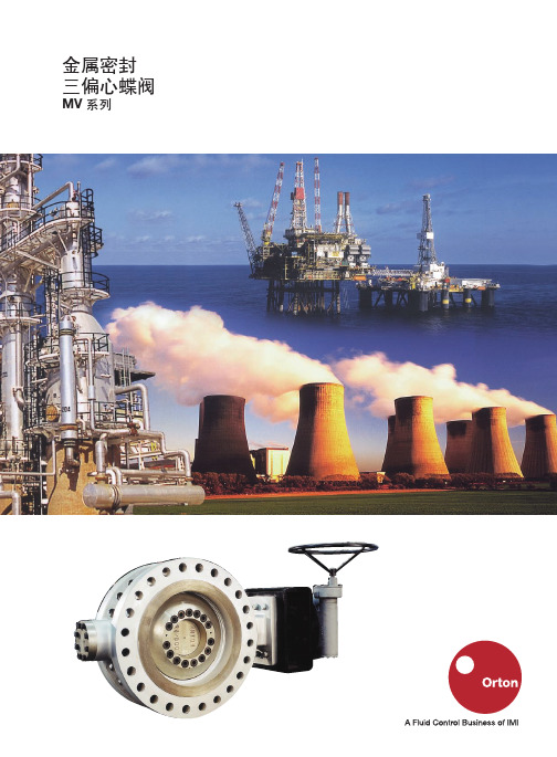
金属密封三偏心蝶阀MV 系列PAGE 2能源领域的应用Orton 是IMI 严酷工况事业部CCI 最主要的阀门制造商,作为全球领先的专业流体控制产品制造商,其阀门应用在工业各领域。
Orton料以及医药等领域。
A S H E L L P H O T O G R A P HOrton 更具有在苛刻工况下应用的优势Orton 金属阀座三偏心在全球范围内以独一无二的操控性、可靠性、紧凑性及实用性著称;其主要应用于苛刻高压严密关断、高温、深冷、节流及隔离工况。
遍布世界各地的各种应用TMAPAGE 3PAGE 4三偏心金属密封蝶阀Orton MV 系列• 使用温度范围:-196ºC 至+815ºC (-320ºF 至+1500ºF)• 弹性金属密封• 扭矩密封• 阀杆和阀体上的一体式阀位指示• 三偏心设计• 全金属结构• 零泄漏双向严密切断• 90°旋转无磨擦开启• 压力等级范围:ANSI Class 150 至ANSI Class 2500• 本质火灾安全和火灾测试• 多种材料可供选择• 完全符合API 609的防吹出结构应用标准• 设计规范API 609BS 5155ANSI B16.34ASME VIII DIN 3840• 法兰标准ANSI ISO DIN JIS• 面心距标准API 609ISO 5752ANSI B16.10• 测试标准API 598 - API 6D (zero leakage)ISO 5208 rate A ANSI B16.104 Cl.VI DIN 3230 rate 1BS 6755 rate A• 火灾测试标准API 607 4th edition BS 6755ISO/FDIS 10497• 质量标准ISO 9001• 防渗漏标准TA-LUFT Point 3.1.8.4阀门尺寸• 2" - 160" Class 150• 2" - 80" Class 300• 3" - 60" Class 600• 6" - 48" Class 900• Class 1500 and 2500 特殊要求阀体结构型式• 双法兰• 支耳式• 对夹式• 焊接式• 特殊要求的其它型式三偏心金属密封蝶阀Orton MV 系列阀门主要材料表Standard CS Standard SS CS NACE阀体A216 WCB A351 CF8M/CF8/CF3M/CF3A216 WCB阀座密封W.O.SEAT ST. GR.21W.O.SEAT ST. GR.21W.O.SEAT ST. GR.21阀板A216 WCB A351 CF8M/CF8/CF3M/CF3A216 WCB阀轴ASTM A182 Gr.F6A CL.III ASTM A479 XM19 UNS S20910ASTM A564 Tp.630 H1150 D (17-4 PH)密封圈ASTM A240 Tp.430 + H.D.G.UNS31803 (Duplex) + H.D.G.ASTM A240 Tp.430 + H.D.G.(Alternative 316 solid forcryogenic service)填料High-density graphite High density graphite High density graphiteLCB WC6 / WC9254 SMO®阀体ASTM A352 LCB A217 WC6 / WC9ASTM A351 CK-3MCuN阀座密封W.O.SEAT ST. GR.21W.O.SEAT ST. GR.21ASTM A351 CK-3MCuN阀板ASTM A352 LCB A217 WC6 / WC9ASTM A351 CK-3MCuN阀杆ASTM A564 Tp.630 H1150 ASTM A182 Gr.F6A CL.III A479 UNS S31254D (17-4 PH)密封圈UNS31803 (Duplex) + H.D.G.UNS31803 (Duplex) + H.D.G.A240 UNS S31254 + Reinf. graph.(Solid 316 or Inconel X625 fortemperature above 426°C)填料High-density graphite High density graphite High density graphiteMonel®Bz - Al Duplex阀体A494 M-35-1B148 C95800UNS S31803 or ASTM A890 gr.4A阀座密封A494 M-35-1B148 C95800W.O.SEAT ST. GR.21阀板A494 M-35-1B148 C95800UNS S31803 ASTM A890 gr.4A阀杆Monel K500Monel K500UNS S32750 (SuperDuplex) orASTM A 240 - UNS S32750密封圈Monel 400 + H.D.G.Monel 400 + PTFE UNS S31803 + HDG orASTM A240 UNS S31803gr.4A填料High density graphite PTFE High density graphiteTitanium Alloy 20lnconel®阀体ASTM B367 Gr.2A351 CN7M INCONEL 625 (UNS N06625)阀座密封ASTM B367 Gr.2Stellite®W.O.SEAT ST. GR.21阀板ASTM B367 Gr.2A351 CN7M INCONEL 625 (UNS N06625)阀轴ASTM B348 Gr.5lncoloy 825INCONEL 625 (UNS N06625)密封圈ASTM B348 Gr.2 + H.D.G.lncoloy 825INCONEL 625 + H.D.G. (UNS N06625)填料High density graphite High density graphite High density graphitelncoloy®Hastelloy®阀体lncoloy 825Hastelloy C276阀座Integral W.O.SEAT ST. GR.21阀板lncoloy 825Hastelloy C276阀杆Incoloy 825Hastelloy C276密封圈Incoloy 825 + Reinf. graph.Hastelloy C276 + Reinf. graph.填料High density graphite High density graphite其余材料可按要求定制Stellite®is a registered trademark of Deloro Stellite Company, Inc.254 SMO®is a registered trademark of Avesta Sheffield AB.Monel®, Inconel®, Incoloy®are registered trademarks of Inco Alloys International, Inc.Hastelloy®is a registered trademark of Haynes International, Inc.PAGE 5PAGE 6三偏心金属密封蝶阀Orton MV 系列Orton 独特的三偏心设计,彻底消除了阀板密封圈和阀座密封之前的磨擦,因此,有效防止因磨损而导致的泄漏可能性,从而延长其使用寿命。
MVS中高压分布与控制系统-开关设备-金属封闭开关设备-MVS中高压38kV负荷断路开关说明书

Medium-voltage power distribution and control systems > Switchgear > Metal-enclosed switchgear— MVS medium-voltage38 kV load interrupter switchContentsGeneral Description . . . . . . . . . . . . . . . . . . . . . . . . . . . 8 .3-2MVS Load Interrupter Switchgear . . . . . . . . . . . . . . . 8 .3-2Devices . . . . . . . . . . . . . . . . . . . . . . . . . . . . . . . . . . . . . 8 .3-6Switch Technical Data . . . . . . . . . . . . . . . . . . . . . . . . . 8 .3-6Motor Operated MVS . . . . . . . . . . . . . . . . . . . . . . . . 8 .3-7Metering . . . . . . . . . . . . . . . . . . . . . . . . . . . . . . . . . . . 8 .3-8Automatic Transfer Control . . . . . . . . . . . . . . . . . . . . . 8 .3-9Surge Protection . . . . . . . . . . . . . . . . . . . . . . . . . . . . 8 .3-10System Options . . . . . . . . . . . . . . . . . . . . . . . . . . . . 8 .3-11Layouts and Dimensions . . . . . . . . . . . . . . . . . . . . . . 8 .3-13MVS Layouts . . . . . . . . . . . . . . . . . . . . . . . . . . . . . . . 8 .3-13Application Data . . . . . . . . . . . . . . . . . . . . . . . . . . . . . 8 .3-17Weights . . . . . . . . . . . . . . . . . . . . . . . . . . . . . . . . . . . 8 .3-17MVS Load Interrupter SwitchgearEaton’s MVS Load Interrupter Switchgear is an integrated assembly of switches, bus and fuses that is constructed for medium-voltage circuit protection. All major components are manufac t ured by Eaton, establishing one source of responsibility for the equipment’s performance and ensuring high standards in quality, coordination, reliability and service.A complete line of Eaton switches and fuses is available:■■38 kV voltage class■■600 A continuous loadinterrupting ratings■■Non-fused or fused with current limiting or boric acid-type fuses■■Manual or motor operated■■Indoor or outdoor non-walk-in enclosures■■Single switches and transformer primary switches■■Duplex loadbreak switch arrange m ents for selection of alternate feeds■■Lineups with main bus■■Standard arrangements with auto m atic transfer control systems (two sources feeding one bus or two sources feeding two buses on a split bus with tie switch) Standard design configurations for:■■NEMA T pads for cable lugs■■Surge arresters■■Instrument transformers■■Control power transformers■■Power Xpert T and IQelectronic metering■■Other auxiliary equipmentOutdoor Duplex with Customer MeteringApplication DescriptionEaton’s Load Interrupter T ype MVSmetal-enclosed switchgear provides safe,reliable switching and fault protectionfor medium-voltage circuits rated to38 kV. T he MVS switch is ideal forapplications where high duty cycleoperation is not required.MVS switchgear has the advantage oflow initial cost inherent in switch designswhile offering the characteristics mostvital to safety and coordination.The MVS switch’s quick-make, quick-break mechanism provides full-loadcurrent interrupting capability whilefuses provide accurate, permanentlycalibrated short circuit detecting andinterrupting capabilities. Visibility ofactual blade position improves safetyby giving positive assurance of circuitde-energization.Standards and CertificationsEaton’s MVS load interrupter switchgearmeets or exceeds the requirements ofthe following industry standards:■■IEEE T Standard C37.20.3■■ANSI C37.57■■NEMA SG5■■Canadian Standard CAN/CSA RC22.2 No. 31Type MVS switches meet or exceedthe requirements of the followingindustry standards:■■IEEE Standard C37.20.4■■ANSI C37.58■■ANSI C37.22■■NEMA SG6■■Canadian Standards CAN/CSA C22.2No. 193 and CAN/CSA C22.2 No. 58Load interrupter switches should notbe used to interrupt load currents abovetheir interrupting rating of 600 A, asthey are not designed nor tested forinterrupting fault currents on electricalsystems . Optional fuses can be providedfor phase overcurrent protection .3838150150600–1200600–12004050.46581.92531.5Switch MechanismThe quick-make, quick-break mecha n ism uses a heavy-duty coil spring that provides powerful opening and closing action. T o close the switch, the handle is inserted into the spring charging cam, then rotated upward through an angle of 120 degrees. This action charges the operating spring, as the mechanism is forced past toggle. The stored energy of the spring is released and transferred to the main shaft that snaps the switch closed.As a result of the over-toggle action, the blades are moved independently of the operator. It is impossible to operate the switch into an intermediate position.To open the switch, the handle is inserted into the spring charging cam and rotated downward through 120 degrees resulting in charging of the operating spring,then releasing its stored energy in similar sequence.Quick-Break DE-ION Arc InterruptionWith the switch closed, both main andauxiliary (flicker) blades are closed, andall of the current flows through the mainblades. T he flicker blades are in the closedposition in the arc chutes, but are past thearcing contacts and thus carry no current.As the main blades open, current istransferred momentarily to the flickerblades, which are held in the arc chutesby high pressure contact fingers. T hereis no arcing at the main blades.When the main blades reach a pre-determined angle of opening, a stoppost on the main blades prevents furtherangular movement between the mainand flicker blades. T his starts the flickerblades out of the high pressure contactsin the arc chutes and as contacts arebroken, the flicker blades are snappedinto position by their torsion springs.The heat of the arc, meanwhile, releasesa blast of de-ionizing gas from thegas-generating material of the arc chute.This combination of quick-break andDE-ION action quickly extinguishes thearc and the circuit is safely de-energized.A non-fused switch has the ability to closeand latch four times when rated 40 kA,and one time when rated 61 kA, andcontinue to carry rated current thusadding a large margin of integrity tothe electrical system.Bus Insulation SystemAll bus runs are supported using a highstrength and high creep, finned supportproviding in excess of 24.00 inches(609.6 mm) for 38 kV, of creep distancebetween phases and ground. T he moldedhigh track-resistant fins are constructedas standard of Aramid nylon or optionalCycloaliphatic epoxy.■■Significantly superior bus bracingthan standoff type A20 insulators■■Significantly increased creep distancephase-to-phase and phase-to-ground■■Improved endurance fromfault incidents■■Minimizes bus system failures dueto tracking■■Eliminates additional groundplanes in the switchgear for bussupporting systemsBus SupportFigure 8.3-1. Switch OperationBoth Blades Disengaged Main, Flicker BladesEngagedMain Blades Disengaged,Flicker Blade EngagedDuplex Switch ConfigurationTwo MVS load interrupter switch sections can be used to provide cost- effective source selectivity with a common load side bus feeding one load (fused or nonfused). Key interlocks are a standard feature provided to per m it only one switch to be closed at a time and prevent opening any switch door unless both switches are open.Figure 8.3-2. Typical Duplex Switch Configuration with One K1 Key— Dimensions in Inches (mm)Loadbreak Switch with Grounding Jaw The loadbreak switch can be supplied with optional grounding jaws for auto-matic grounding of the load circuit. When the switch is opened, the switch main blades engage grounding jaws to ground the load circuit. This feature cannot be used in a duplex switch configuration . The ground jaw option is available at38 kV. It is meant for applying a static ground, and is not rated for carrying fault currents.Figure 8.3-3. Typical Feeder Switch with Optional Grounding Jaw (38 kV)Figure 8.3-4. Typical Section View of Feeder Switch with Optional Grounding Jaws— Dimensions in Inches (mm)ConstructionT ypical Switch with Front Door Opena Switch MechanismQuick-make, quick-break storedenergy operation.The opening and closing of the switch blades is done by the operating spring.An operator’s actions only charge and release the operating spring.The switch blades cannot be operatedin any intermediate positions. Duringthe closing operation, full clearancebetween blades and stationarycontacts is maintained until theswitch mechanism goes over toggle.The switch mechanism has onlymetal-to-metal linkage—no chainsor cables are used.Arc interruption takes place betweencopper-tungsten tipped auxiliary(flicker) blade and arcing contacts witha DE-ION T arc chute; no arcing takesplace between the main blades and the stationary contacts to prolong the lifeof the main blades.Blow-out forces cannot be transmit t ed to the operating handle.b■Provisions for Padlocking DoorHandle not visible in the photo.c■Inspection W indowA large 8.00-inch x 16.00-inch(203.2 x 406.4 mm) gasketed,rectangular, high impact viewingwindow permits full view of theposi t ion of all three switch bladesthrough the closed door.d■Full Height Main DoorThe door has a return flange and tworotary latch-type handles to providelatching members held in shear. Itcloses over a projecting frame.e■Foot-Operated Door Stopf■Grounded Metal Safety BarrierPrevents inadvertent contact with anylive part, yet allows full-view inspec-tion of the switch blade position.g■Door InterlockPrevents the door of the enclosurefrom being opened when the switchis closed.h■Switch InterlockPrevents inadvertent closure of theswitch if the door of the enclosureis open.l Provisions for Door and SwitchKey Interlocksm The Operating HandleIt is conveniently located behind asmall access door giving the structurea smooth homogeneous appearanceand discourages casual contact byunauthorized personnel.n Switchgear AssemblyRating NameplateSwitch Operating Compartment Door OpeneSwitch Technical DataTest DataEaton’s MVS switch ratings have been thoroughly tested in recognized high power laboratories with certified inspectors from both UL T and CSA organizations. T ests were performed to substantiate all published ratings in accordance with ANSI, IEEE, CSA and NEMA standards.The testing program included tests of:■■Basic impulse levels■■Momentary withstand■■Short-time withstand■■Fault closing■■Load interrupting at various loads, various power factors■■Mechanical life tests■■Temperature rise testThese tests verified not only the per-formance of the switch and integrated switch-fuse assembly, but also the suitability of the enclosure venting, rigidity and bus spacing.The mechanical life test subjected the MVS switch to a number of no load cycles greater than the requirements tabulated in ANSI C37.22 standards. T here were no moving or current carrying part failures as a result.The Fault Close and Load Interrupting test demonstrated significant improved performance above ANSI/IEEE standards. See T able 8 .3-3 and T able 8 .3-4 for results.38381501506006004050.46581.92531.5386005538384050.46581.91111a When RBA expulsion fuses are used, and two ratings appear, the lower rating applies when thelower-rated switch (15 kV, 40 kA fault close, 25 kA short-time current) versus the higher rating that applies when the higher-rated switch (15 kV, 61 kA fault close, 38 kA short-time) is used.Motor Operated MVSApplicationEaton’s MVS Pow-R-Drive E motor operator makes possible the safety and convenience inherent in remote switch operation.Motor Operated MVS Switch DescriptionA MVS Pow-R-Drive motor operatedswitch is a standard, manually operatedswitch in combination with a heavy-dutyelectric motor-driven linear actuator thatcharges the spring. T he linear actuator islocated in a separate isolated low-voltagecompartment. During electrical operation,it smoothly and quietly extends orretracts the proper distance to cause theswitch mechanism to operate.Standard motor operators are mounted inthe switch enclosure. T his eliminates theneed for a separate motor compartmentconserving floor space.Manual Operation OverrideManual OperationTo operate manually, loosen the holdingscrew that keeps the pin connecting thelinear actuator to the mechanism, andremove the pin. Remove the clevis pinon the support of the bottom of the linearactuator. Unplug the cord from thedisconnect i ng terminal block as theactuator is removed and set the actuatoraside. T he switch can now be operatedmanually with the removable handle.Lock Open Key InterlockA keyed lock is standard to lock the switchin the open position only.This lock not only locks the switch in theopen position, but also breaks theelectrical motor contacts integral to themotor control circuit and permits the keyto be removed. With the key, the operatorcan then open the lock on the switch door.This scheme gives positive assurance thatthe switch is open and cannot be closedwith the door open.MeteringElectronic Metering and Communications ApparatusMVS switchgear assemblies can be equipped with Eaton’s family of Power Xpert T and IQ digital meters to monitor a power circuit’s electrical quantities within the capabilities of each device. Eaton’s power management products provide hardware and softwaresolu t ions that allow customers to interface with their switchgear at varying levels of sophistication. Power Xpert and IQ Meters monitor common electrical parameters and communicate the data via standard industry protocols and optional web interfaces. Power Xpert Gateways consolidate devices into a single web browser interface and provide Ethernet connectivity. Eaton’s Foreseer web-based software system can display, analyze and store data from multiple devices across the facility to enable management of the customer’s power system.Electronic Metering Outdoor Enclosures Weatherproofing complying with the requirements of IEEE standard C37.20.3 is available for MVS switch g ear assemblies. The weatherproofing consists of sloped roof panels that are joined together with caps. Doors and rear covers are fully gasketed. Externally accessible louvered filtered covers, top and bottom, front and rear, are provided for ventilation. At least one 250 watt heater is provided in each vertical section. Power for the heaters may be supplied from an external source, or an optional integral control power transformer may be specified to provide power for the heaters.Outdoor EnclosurePower Xpert MeterPXM 4000/6000/8000IQ 130/140/150/250/260Automatic Transfer ControlT wo-Switch Automatic T ransferApplicationEaton’s MVS switchgear with an automatic transfer control system is an integrated assembly of motor operated MVS switches, sensing devices and control components. Available in 38 kV class.It is typically applied where the continuity of service for critical loads from two power sources in either a main/main or a main/ tie/main configuration is desired.MVS switchgear with an automatic transfer control system can meet most automatic throwover requirements as it has a wide variety of operational sequences embodied in one standard automatic transfer control system. Please note that the duty cycle of load interrupter switches is limited by ANSI Standard C37 .22 . Refer to T able 8 .3-3for maximum number of switching operations allowed . If the number of switching operations is expected to exceed the maximum allowed, then load interrupter switches should not be used . Use circuit breakers (refer to T ype MSB, MEB, MEF or V CP-W switchgear designs) . Also note that the operating times of Eaton’s motor operated load interrupter switches are much longer compared to circuit breakers, therefore, the switches are not suitable for closed-transition transfer applications . Use circuit breakers if closed-transition transfer is required . T ypical T wo-Switch AutomaticT ransfer Using ATC ControllerEaton’s ATC-900 controller continu o uslymonitors all three phases on both sourcesfor correct voltages. Should the voltageof the normal source be lost while thevoltage of the alternate source remainsnormal, the voltage sensing function inthe ATC controller will change statestarting the time delay function. If thevoltage of the normal source is notrestored by the end of the time delayinterval, the normal switch will open andthe alternate source switch will close,restoring power to the load.ATC ControllerEaton’s ATC controller is equipped todisplay history information via the frontpanel. ATC-900 controller stores 320 timestamped events. Oscillographic data forlast 10 events can be downloaded via theUSB port or displayed in the controller’sdisplay window. T he controller allowscommunications via RS-232 or Modbusthrough RS-485 port, Ethernet or viaUSB interface.ATC ControllerStandard Features■■Voltage sensing on both sources isprovided by the ATC controller■■Lights to indicate status of switches,sources, etc.■■Interlocking to prevent paralleling ofsources via software■■Control power for the automatictransfer control system is derived fromthe sensing voltage transformers■■Manual override operation■■Open transition on return to normal■■Programmable time delays on bothsources, “OFF DELA Y” and “ON DELA Y”■■Four programmable digital inputsand outputs■■Single-source responsibility; all basiccomponents are manufac t ured by Eaton■■Key interlocking of operating systemand doors where required to provideoperator safetyOptional Features■■Lockout on phase and/or groundovercurrents and/or internal bus faults■■Blown fuse overcurrent lockout■■Load current, power and PF meteringwith optional dcT module■■24 Vdc control power input■■Up to four additional I/O modules, eachwith four programmable digital inputsand digital outputsSurge ProtectionIEEE standard C62.11 for Metal Oxide Surge Arresters lists the maximum rated ambient temperature as 40 °C. T he ambient temperature inside an Eaton MVS switchgear vertical section may exceed this temperature, especially in outdoor applications where solar radiation may produce a significant contribution to the temperature. T able 8 .3-6 lists the recommended minimum duty cycle voltage rating for various system grounding methods. Surge arrester rating is based upon the ambient air temperature in the switchgear vertical section not exceeding 55 °C.33.0034.50 38.0027303022.0024.4024.403030—24.4024.40———————27303022.0024.4024.4036363629.0029.0029.004548—36.5039.00—Note: MCOV = Maximum Continuous Operating Voltage.System OptionsPartial Discharge Sensing and Monitoring for SwitchgearPartial Discharge in SwitchgearPartial discharge (PD) is a common name for various forms of electrical discharges such as corona, surface tracking, and discharges internal to the insulation. It partially bridges the insulation between the conductors. T hese high frequency discharges are essentially small arcs occurring in or on the surface of the insulation system when voltage stress exceeds a critical value. With time, airborne particles, contaminants and humidity lead to conditions that result in partial discharges. Partial discharges start at a low level and increase as the insulation becomes deteriorated. Examples of partial discharge inswitchgear are surface tracking across bus insulation, or discharges in the air gap between the bus and a support (such as where a bus passes through an insulating window between the sections of the switchgear). If partial discharge activity is not detected and corrected, it can develop into a full-scale insulation failure followed by an electrical fault. Most switchgear flashover and bus failures are a result of insulation degradation caused by various forms of partial discharges.Sensing and MonitoringEaton’s T ype MVS metal-enclosedswitchgear (2.4–27 kV) is corona-free by design. By making switchgear assemblies corona-free, Eaton has made its standard switchgear more reliable. However, as indicated above, with time, airborne particles, contaminants and humidity lead to conditions that cause partial discharges to develop in switchgear operating at voltages 4000 V and above. Type MVS switchgear can be equipped with factory-installed partial discharge sensors and a partial discharge sensing relay for continuous monitoring under normal operation. T imely detection ofinsulation degradation through increasing partial discharges can identify potential problems so corrective action can be planned and implemented long before permanent deterioration develops. Partial discharge detection can be the foundation of an effective predictive maintenance program. T rending of partial discharge data over time allows prediction of failures, which can be corrected before catastrophic failure occurs.The PD sensing and monitoring system consists of Eaton’s InsulGard T relay and PD sensors, specifically developed for application in the switchgear to work with the relay. T here are two types of PD sensors used in the switch g ear: the first sensor is a coupling capacitor type sensor developed for use with 5 kV, 15 kV and 27 kV switchgear.The coupling capacitor sensor detects partial discharges within the switchgear cubicle and/or adjacent cubicles, and is typically installed on the load side of the feeder switches or on the main bus. T he second sensor is a small donut type radio frequency current transformer (RFCT). It is designed for installation around the ground shields of incoming or outgoing power cables. It detects partial dis c harges in power cables and monitors for external electrical noise.Typically one set of coupling capacitor sensors is used at every two cubicles. One RFCT sensor is used for each incoming and outgoing power cable circuit.Output signals from sensors (coupling capacitor and RFCT) are wired out to terminal blocks for future or field use, or connected to the InsulGard relay. One InsulGard relay can monitor up to 15 input signals, as well as temperature and humidity. T he temperature andhumidity sensors are included with each InsulGard relay system. T he relaycontinuously monitors the switchgear primary system for partial discharges and provides an alarm signal (contact closure) when high PD level is detected. Also, data analysis and diagnostics by Eaton engineers can also be provided by remote communication with the InsulGard relay.The sensors and InsulGard relay are optional in MVS switchgear .Figure 8.3-5. InsulGard Relay SystemCoupling CapacitorT ype PD SensorRFCT SensorInsulGard Relay (PD Monitoring)Partial Discharge Sensors and Monitoring for SwitchgearFigure 8.3-6. How the Process Works—Sensing and Data CollectionFigure 8.3-7. Typical Partial Discharge Sensor Connections in MVS Switchgear (5–27 kV)Note: Use one set of PD sensing capacitors at every two vertical sections, or portion thereof. Use one RFCT at each incoming/outgoing cable circuit.PD SensorsCoupling Capacitor detects partial discharges internal to switchgear compartment.RFCT detects partial discharges in customer’s cables up to 100 ft from switchgear.MVS LayoutsTypical Arrangements—38 kVThe drawings in this section represent the most common arrangements. Layouts shown are for rear-accessible equipment . Front-accessible designs are available—refer to Eaton . Many other configurations and combinations are available. T wo voltage transformers for metering and one control transformer for auxiliary power can be mounted in the structures shown. For control power above 1 kVA, additional space is required. Depth of units will vary due to cable entrance and exit requirements, the addition of lightning arresters, instrument transformers, special cable terminators, etc. Cables are shown out top and bottom for layout only. T op or bottom must be selected for incoming and for outgoing cables. Cable sizing is based on two 500 kcmil XLP or EPR insulated cables per phase using preformed slip-on cable termination devices.Note: Width for Utility Metering Structures may vary.ATC = Automatic T ransfer Controller (see Page 8 .3-9)M = Motor OperatorPLC = Programmable Logic ControllerNote: Not to be used for construction purposes unless approved.Figure 8.3-9. Rear Access, Cable Exit—Top or BottomNote: Low height dimensions are for non-fused, manually operated switch only. For all motor operated switches and all fused switches, tall height dimensions apply.1 or 280.00 (2032.0)Figure 8.3-10. Rear Access, Cable Entry and Exit—Top or BottomNote: Low height dimensions are for non-fused, manually operated switch only. For all motor operated switches and all fused switches, tall height dimensions apply.1 or 280.00 (2032.0)a When high continuous current fusing or instrumentation is required, consult the Eaton factory for guidance.Note: A = Power Cable to Load. B = Power Cable from Source. See Figure 8 .3-8, Figure 8 .3-9 and Figure 8 .3-10 as applicable for dimension D on Page 8 .3-14 and Page 8 .3-14.Not to be used for construction purposes unless approved.Figure 8.3-12. Typical Anchor Plan—38 kV Outdoora Typical location for four (two front, two back) Eatonsupplied tie down clips for all 27–38 kV. Customer provided bolts for anchoring should be 0.50–13 min. SAE Grade 5 M12 x 1.75 min. CL 10.9 or stronger, and tightened to 75 ft-lb.b Door swing equals vertical section width at 90º.c Minimum clearance on side. Local jurisdictions may requirea larger clearance.d Minimum clearance in front is the width of the widestvertical section plus 1.00 inch (25.4 mm), but not less thanthat required by the NEC T. Local jurisdictions may requirea larger distance.e Minimum clearance in rear is 30.00 inches (762.0 mm).If rear doors are supplied, the minimum clearance is thewidth of the widest vertical section equipped with a reardoor plus 1.00 inch (25.4 mm). Local jurisdictions mayrequire a larger clearance.f Finished foundation’s surface shall be level within 0.06-inch(1.5 mm) in 36.00 inches (914.4 mm) left-to-right, front-to-backand diagonally, as measured by a laser level.g Locations for 0.50-inch (12.7 mm) anchor bolts.Figure 8.3-13. Typical Anchor Plan—38 kV IndoorWeightsNon-fused switch Fuses (3), add Indoor transition 2000 (908)300 (136)1100 (499)2400 (1090)300 (136)—Outdoor throat Motor operator adder —400 (182)1200 (545)400 (182)Eaton1000 Eaton BoulevardCleveland, OH 44122United StatesEaton .com© 2019 EatonAll Rights ReservedPrinted in USAPublication No . CA022011EN / Z22791Eaton is a registered trademark.All other trademarks are property。
火力发电厂管道阀门振动危害及对策分析
火力发电厂管道阀门振动危害及对策分析发布时间:2022-05-23T05:12:31.140Z 来源:《当代电力文化》2021年36期作者:孙忠磊[导读] 作为火力发电厂中非常常见的设备材料,管道、阀门在生产运行中也占据重要地位,其振动会给火力发电厂的正常运转带来影响。
孙忠磊大唐淮南洛河发电厂安徽省淮南市 232008摘要:作为火力发电厂中非常常见的设备材料,管道、阀门在生产运行中也占据重要地位,其振动会给火力发电厂的正常运转带来影响。
本文在简述管道阀门振动危害的基础上,对管道阀门振动类型进行了简要分析;在简述管道阀门振动治理原则的基础上,对管道阀门振动对策进行了探索,以促进火力发电厂的正常、稳定运转。
关键词:管道;火力发电厂;阀门前言目前,火力发电厂的运行原理基本都是通过加热燃烧燃料带动水蒸汽,借助于设定的发电设置进行电力的生产,在火力发电厂的生产系统中,管道与阀门具有着必不可少的地位。
在生产系统当中,管道起到血管作用,阀门可对系统开关进行控制。
在技术进一步发展的现在,火电单机容量得到了进一步增长,其在管道与阀门的技术和材料方面要求越来越高。
然而,受阀门管道内流体介质、运行、选型、安装、设计、构造与材料的影响,管道阀门常出现振动情况,影响其使用寿命,最终对经济效益产生影响。
在此背景下,需加强对火力发电厂管道阀门振动的研究与分析,减少其振动状况,保证其正常发挥作用。
1管道阀门振动造成的危害在对于管道与阀门的震动情况进行分析时,应从静应力与动态两个方面进行分析,其中,疲劳损害主要是构件破坏,振动响应体现在时间函数上。
根据对压力管道阀门疲劳损害的分析,其主要表现包括低循环疲劳破损与高循环疲劳破损。
致使管道阀门出现振动情况的因素种类较多,在进行应对时,应根据具体情况进行分析。
本文在进行探索的过程中,首先针对于管道阀门振动的危害进行分析,根据火力发电厂实际运行情况,管道阀门振动将导致其使用时间减少、发电系统损害、管道阀门破损以及仪器仪表的损坏。
台达高压变频器2200V-6900V型录说明书

绿色驱动 运转不息能源基础设施暨工业解决方案高压变频器• 零组件• 电源及系统• 风扇与散热管理• 汽车电子• 工业自动化• 楼宇自动化• 资通讯基础设施• 能源基础设施暨工业解决方案• 视讯解决方案台达电子创立於 1971 年, 为全球提供电源管理与散热解决方案。
面对日益严重的气候变迁, 台达长期关注环境议题,秉持「环保节能 爱地球」的经营使命,持续开发创新节能产品及解决方案丶不断戮力提升产品的能源转换效率,以减轻全球暖化对人类生存的冲击。
近年来,台达集团已逐步从关键零组件制造商迈入整体节能解决方案提供者,深耕「电源及零组件」丶「自动化」与「基础设施」三大业务范畴。
台达总部位於台湾,致力於创新研发,每年投入集团营业额约8%作为研发费用,据点遍布全球包括中国大陆丶日本丶新加坡丶泰国丶美国及欧洲等地。
秉持对环境保护的承诺,台达不断提高电源产品转换效率,以期能为人类守护一个永续发展的环境。
关於台达事业范畴电源及零组件自动化基础设施2015承诺RE100Carbon NeutralityRace to Zero2018台达加入RE100倡议组织专注於7项联合国永续发展目标• 企业自主减碳 (SBT)• 揭露气候变迁资讯 (TCFD)• 参与气候政策承诺2030年台达主要营运据点:• 普设充电桩• 公司车转型电动车• 提供员工客户使用电动运具之诱因• 承诺台达全球所有据点2030年前使用100%再生电力• 承诺2030年达到碳中和台达承诺 "We Mean Business"承诺EV1002021承诺2030年全球厂办100%使用再生电力及达到碳中和• 签署Business Amibitionfor 1.5℃目 录生产基地与制程介绍台达高压变频器应用价值台达高压变频器特色 产品系列介绍如何安装与接线6-78-910-1112-15 16-17产品选型表与外观成功案例-发电与供热 成功案例-钢铁与冶金成功案例-水泥成功案例-市政工程填写产品选型表18-1920-2122-2324-2526-2728台达高压变频器高效丶可靠,为企业大幅减少工厂丶马达用电支出,降低排碳量,并提高生产效率丶延长设备寿命。
GE PC_MV7000_cn_cy_20130508
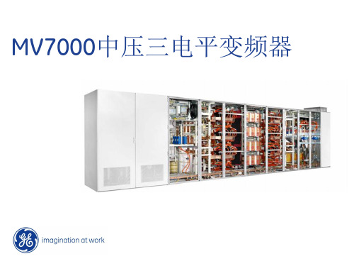
MV7000中压变频器-3.3KV
控制和冷却 AFE 主动前端整流 直流母线 三电平逆变 交流输出
水冷
变压器
MV7000拓扑结构 (AFE主动前端整流输入)
电动机
12 GE Title or job number 9/26/2013
Collector IGBT Emitter
反并联 二极管
适用于小功率和中等功率变频器
IEGT 的技术改进:
适用于中等功率和大功率变频器
– 无导线连接技术: 不会因为导线焊接形成的分层结构而产生元件开裂 – 陶瓷压装技术: 避免电机在低频运行时需要降容
6 GE Title or job number 9/26/2013
– 改善电机电压波型 – 电机电流包含更低的谐波电流
采用先进的技术:
– 减小了设备的尺寸 – 更好的鲁棒性 – 提高了服务寿命
适用于交流感应电动机和同步电机
2 GE Title or job number 9/26/2013
MV7000中压变频器
MV7000 – 压装式IEGT (PPI )
门驱动控制板
逆变桥 直流母线
主动前端整流桥
冷却单元
控制柜
March 2011
23 GE Title or job number 9/26/2013 23
|
MV7000中压变频器
MV7927 (27MW - 10kV)
逆变桥
压装式模块
24 GE Title or job number 9/26/2013
MV7000中压变频器-6.6KV
DC - = - 3/6 VDC DC + = + 3/6 VDC
莫克维迪轴流式调节阀
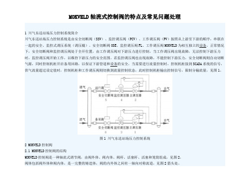
MOKVELD轴流式控制阀的特点及常见问题处理1 川气东送站场压力控制系统简介川气东送站场压力控制系统是由安全切断阀(SSV)、监控调压阀(PCV)、工作调压阀(PV)按照从上游至下游的顺序,串联在一起的安全、监控式调压系统(调压橇)。
安全切断阀OSE、监控调压阀FL、工作调压阀MOKVELD为相互独立的设备。
正常情况下,安全切断阀和监控调压阀处于全开位置,由工作调压阀对下游压力进行控制。
当工作调压阀出现故障,无法控制下游压力时,监控调压阀开始工作,以维持下游压力的安全范围。
若监控调压阀也出现故障,不能控制下游压力,安全切断阀则自动切断气源,同时控制机柜开启备用回路,以保证下游管道和设备的安全。
当需要进行流量控制时,控制机柜接到SCADA系统的信号,供气流量超过设定值时,控制机柜和工作调压阀则切换到流量控制状态,此时控制机柜输出控制信号,限制分输流量,见图1。
图1 川气东送站场压力控制系统2 MOKVELD控制阀2.1 MOKVELD控制阀的结构MOKVELD控制阀是一种轴流式调节阀,由阀外体、阀内体、阀杆、活塞杆、活塞和笼筒组成,见图2。
阀体包括阀外体和阀内体,是一完整的铸造体,阀的内外体之间有一轴向对称流道,见图2箭头处。
笼筒是减压阀的关键部件,壁面上有许多孔洞,MOKVELD控制阀选用三层笼筒,即笼筒壁面分三层,每层按一定规律分布有许多孔洞,三层壁面按一定的要求组合为一体。
活塞杆与阀杆构成一个90°的角式传动机构(见图2),活塞借助此传动机构在导轨内沿阀门的中心线运动,活塞杆与阀杆上4 5°的齿条相互啮合,阀杆上下传动,带动活塞杆及活塞在全行程上左右运动。
活塞的端面上均匀分布有孔洞,以使活塞内外压力平衡,左右运动时不受轴向压力的影响。
1)阀外体;2)阀内体;3)活塞杆;4)阀杆;5)活塞;6)笼筒图2 MOKVELD控制阀结构示意图2.2 MOKVELD控制阀的特点2.2.1 介质的轴流性由于采用轴向对称流道,完全避免了间接流和流向不必要的改变,最大限度地提高了单位直径上的流通能力,大大降低了噪音和紊流的形成,并可以防止上游未经过处理的流体腐蚀阀门。
EVA装置超高压特殊阀门控制优化及可靠性提升

第29卷 第07期2022年07月仪器仪表用户INSTRUMENTATIONVol.292022 No.07EVA装置超高压特殊阀门控制优化及可靠性提升杨利丰,李 政,耿昊天(中化泉州石化有限公司,福建 泉州 362103)摘 要:10万吨/年EVA 装置是中化泉州石化有限公司引进的ExxonMobil Chemical 工艺技术的聚烯烃装置。
其工况苛刻,设计压力高达200 MPa,控制及联锁逻辑复杂,开车难度大,国内同类型装置较少,对设备及高压超高压控制阀门的稳定可靠性要求极高。
EVA 装置的高压超高压控制阀门在装置建设、阀门调试,及吹扫初期阶段就出现不同程度的设备问题。
问题隐患不及时解决,会对装置投料开车及装置安全运行产生较大的影响。
通过组织专业力量进行高压超高压阀门的可靠性及稳定性攻关,解决了高压超高压阀门存在的隐患问题,有效提升了其运行的可靠性和稳定性,为EVA 装置平稳高效安全生产提供了有力保障。
关键词:高压超高压阀门;控制优化;可靠性及稳定性中图分类号:TH 文献标志码:AControl Optimization and Reliability Improvement of EVASpecial Ultra-High Pressure ValveYang Lifeng ,Li Zheng ,Geng Haotian(Quanzhou Refining & Chemical Company , Fujian, Quanzhou,362103,China )Abstract:The 100,000 t/a EVA unit is a polyolefin unit with ExxonMobil Chemical process technology introduced by Sino-chemical Quanzhou Petrochemical Co., LTD. It has harsh operating conditions, design pressure up to 200MPa, complicated control and interlocking logic, and it is difficult to start. There are few similar units in China. The stability and reliability of equipment and high pressure control valve are highly required. The high pressure and super high pressure control valve of EVA device has dif-ferent degree of equipment problems in the initial stage of device construction, valve debugging and purge. If the hidden problems are not solved in time, it will have a great impact on the feeding and start-up of the device and the safe operation of the device. By organizing professional forces to tackle the reliability and stability problems of high pressure and ultra-high pressure valves, the hidden problems of high pressure and ultra-high pressure valves are solved, and the reliability and stability of their operation are effectively improved, which provides a strong guarantee for the smooth and efficient safe production of EVA devices. Automatic fire alarm system in refinery and chemical integrated plant, the safe and stable production of petrochemical enterprises is guaranteed, and the automatic fire alarm system, as an independent central system, also plays a key role.Key words:high pressure ultra-high pressure valve;control optimization;reliability and stability收稿日期:2022-03-03作者简介:杨利丰(1971-),男,河北新乐人,本科,高级工程师,部门专家,研究方向:仪表自动化、电信系统。
电动执行器阀门的介绍

一.电动系列1 电动执行器注:红色部分为引申的下一层角行程电动执行器(配角行程图片(1),加配套文字;配图片角行程DKJ系列(1))直行程电动执行器(配图片直行程电动执行器(1)配文字)多转式电动执行器(配图片多转式电动执行器(1),配文字)2电子式单座双座调节阀(配电动调节阀图片(2),以及文字)3电动蝶阀电动蝶阀(配图片电动蝶阀(3))电动风阀(配图片电动风阀(3))4电动百叶式矩形风阀(配矩形风阀(4)及文字)二.气动系列1气动执行器(配图片气动执行器(5)(6))2气动阀门气动调节阀(配图片气动调节阀(7))气动球阀(配图片气动球阀(7))三.相关配套仪表球型铰链(配图片(8))操作器(配图(9))伺服放大器文字说明1角行程电动执行器S D系列智能型电动执行机构是本公司引进法国技术生产的具有世界先进水平的产品, 其主要部件均为进口,产品严格执行国家标准。
目前生产的SD系列包括角行程、直行程、多转式三大类包括调节型、远控型、开关型等,SD系列智能电动执行机构功能齐全,质量稳定,安全可靠,精度高、规格多、重量轻、安装调试灵活方便,广泛应用于电力、冶金、石化、建材、供热、轻工、水处理、脱硫等行业,在工业过程控制系统中发挥着重要作用。
SD系列电动执行机构是自动调节系统的终端控制装置,它接收来自DCS系统调节器或计算机的4~20mA(或1~5V)模拟量信号及断续接点控制信号,输出力矩或力,自动地操纵调节机构,完成自动调节任务。
它也可以通过操作器实现“手动—自动”转换,切换到手动时,用操作器可对执行机构进行远方控制。
角行程电动执行机构,可用于控制各类转角90°的阀门如:蝶阀、球阀、百叶阀、风门、旋塞阀、挡板阀等。
直行程电动执行机构是输出直线位移的电动执行机构,可用于控制各种需要直线位移的调节阀,如单、双座调节阀、套筒阀、高温高压给水阀、隔膜阀、减温水等调节阀。
产品的种类及型式1、SD系列电动执行机构输出方式分成三种:A.角行程—输出0~90°角位移的力矩。
- 1、下载文档前请自行甄别文档内容的完整性,平台不提供额外的编辑、内容补充、找答案等附加服务。
- 2、"仅部分预览"的文档,不可在线预览部分如存在完整性等问题,可反馈申请退款(可完整预览的文档不适用该条件!)。
- 3、如文档侵犯您的权益,请联系客服反馈,我们会尽快为您处理(人工客服工作时间:9:00-18:30)。
美国VINDUM的模块化阀门系统
为您节省大量时间和成本
模块化阀门系统特点:
♦
耐高温,最高350F (170℃) ♦
耐压12,000 psi ♦ 润湿部件材质哈氏合金 更好的性能,质量,价格!
美国Vindum 公司郑重发布了新型Vindum 模块化阀门系统。
现在你可以使用阀门、三通和四通建立并安装一个布局紧凑的流体控制系统,这样不但能够节省成本而且更
快速高效。
新型的MV-210-HC 阀
门使用新型O型圈/支撑环
设计可以有效消除普通阀
门的封装泄露问题。
阀门,三通和四通都
使用了相同的封装和连接
头,这样可以高效快速的
在网格安装板上进行布局
和系统连接
革新的MVS可提高生
产力,可靠性并节省成本
网格安装板节省时间和空间 ♦ 快速建立,简易安装 ♦ 不需要附加的支架 ♦ 适合 1” x 1” 和 25mmx25mm 螺栓
式网格
- 网格安装板可以使用标准尺寸
或是用户定制尺寸
MV ‐210‐HC
VALVE
TWO ‐STEM 4‐WAY VALVE MV ‐TEE ‐HC
特殊定制: MV ‐9STN ‐
MANIFOLD 哈氏合金管线 ∙ 1/16” x .010” ∙ 1/8” x .035” ∙ 1/4” x .035” ∙
1/4” x .065” (In Stock, ready to ship)。