高稳定度直流电源+24V设计说明书
稳压直流电源产品说明书
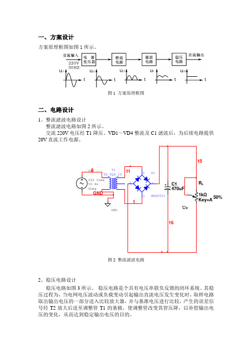
一、 方案设计方案原理框图如图1所示。
图1 方案原理框图二、电路设计1、整流滤波电路设计整流滤波电路如图2所示。
交流220V 电压经T1降压、VD1~VD4整流及C1滤波后,为后续电路提供20V 直流工作电源。
图2 整流滤波电路2、稳压电路设计稳压电路如图3所示。
稳压电路是个具有电压串联负反馈的闭环系统。
其稳压过程为,当电网电压波动或负载变动引起输出直流电压发生变化时,取样电路取出输出电压的一部分送入比较放大器,并与基准电压进行比较,产生的误差信号经T2放大后送至调整管T1的基极,使调整管改变其管压降,以补偿输出电压的变化,从而达到稳定输出电压的目的。
L50%图3 稳压电路3、输出参数调节及负载电路输出参数调节及负载电路如图4所示。
(1)输出电压Uo 及输出电压调节范围:)U (U R R R R R U BE2Z W 22W 1O +"+++=调节Rw 可以改变输出电压Uo 。
(2)最大负载电流Iomax 。
稳压电源正常工作时能输出的最大电流。
调节Rl 可以改变Io 。
50%Q1图4 输出参数调节及负载电路三、电路测试切断工频电源,连接好被测电路。
1、初测。
稳压器输出端负载开路,断开保护电路,接通220V工频电源,调节电位器Rw,观察Uo的大小和变化情况。
观察结果显示,Uo岁Rw线性变化,说明该稳压电路各反馈环路工作基本正常。
2、测量输出电压可调节范围。
接入负载,并调节Rl,使输出电流Io≈100mA,此时接入的负载阻值为156Ω,满足驱动负载在120Ω~240Ω的范围内,如图5所示。
再调节电位器Rw。
当将电位器Rw调节到最大值时,测量输出电压达到限定范围的最小值,此时Uo为6V左右,如图6所示;当将电位器Rw调节到最小值时,测量输出电压达到限定范围的最大值,此时Uo为15V左右,如图7所示,即满足稳压电源输出直流可调电压6V<Uo<15V这一技术指标的要求。
该过程中如不满足要求,可适当调整R1、R2的值。
稳压电源说明书(2U机架式-DC12VDC24VC24V电源三输出-led)
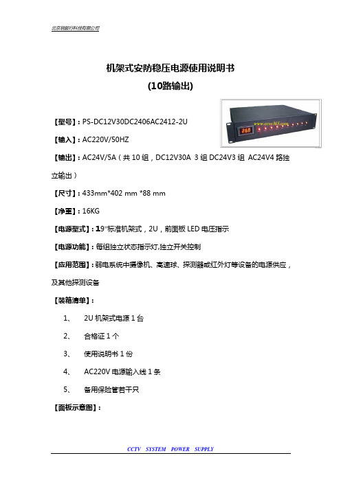
机架式安防稳压电源使用说明书(10路输出)【型号】:PS-DC12V30DC2406AC2412-2U 【输入】:AC220V/50HZ 【输出】:AC24V/5A (共10组,DC12V30A 3组DC24V3组 AC24V4路独立输出) 【尺寸】:433mm*402 mm *88 mm 【净重】:16KG【电源型式】:19”标准机架式,2U ,前面板LED 电压指示 【电源功能】:每组独立状态指示灯,独立开关控制 【应用范围】:弱电系统中摄像机、高速球、探测器或红外灯等设备的电源供应,及其他探测设备 【装箱清单】:1、 2U 机架式电源1台2、 合格证1个3、 使用说明书1份4、 AC220V 电源输入线1条5、 备用保险管若干只 【面板示意图】:Front Panel( 前面板)Rear Panel (后面板)AC 220V Input Fuse按钮数字电压表CECT C T C T C T C T C T C T C T C T C T C TSwitch【输出电压调节】:DC 输出在机箱内电路板有标着VR 的正方形可调电位器,可用十字螺丝刀轻轻调节,顺时针旋转电压增高,逆时针旋转电压降低,可根据需要调节。
AC 输出出厂可根据现场,远近需要定做AC26V 或者其他规格 【产品特点】:R 型变压器可以用作所有电器的电源变压器或隔离变压器。
则于它具有效率高、体积小、体形薄、重量轻、磁漏少、发热低、生产标准化等特点,安全性能符 合世界各国安规,产品得到广泛应用。
特别是励磁电流小,空载损耗低,噪音极小,输出功率大等特点。
在摄像机、音响、精密设备或(在待命状态下需要长期通电的)电源转换器中使用有更突出的表现。
【保险规格】AC220V 输入15A输出每路独立保险(可根据需要换装保险规格,但总功率不得超出) ★特别提示:接入市电时,请特别注意人身安全注意接线端子的正确接法,防止接反不要超负荷使用本产品如遇故障,不要自行拆卸,请及时联系供应商。
Relcross Heavy Duty Power Supply 24V DC 7.0 Amp说明书

Relcross Heavy Duty Power SupplyContinuously Rated 24 V DC 7.0 Amp•Designed to suit most security, fire& access control installations,where battery back up is essential.•Continuously rated.•Fitted with a fire alarm relay.•Output is current regulated, ifoverloaded the output shuts downuntil fault is cleared.•Voltage regulated to correct outputfor battery charging.•Fuse to protect battery fromincorrect connection.•Three way fused distribution boardwith blown fuse indication.•Fan assisted cooling cuts in at hightemperature•Metal enclosure with 20mmknockouts.Stock no: 483086Full specification sheetsfollows:24 V DC – 7.0 Amp continuous – 7.5 Amps IntermittentThe enclosure must be fixed to a vertical flat surface at a maximum ambient temperature of 45 degrees C in a well ventilated areaThis power supply must be installed in accordance with the current IEE regulations covering low voltage power supplies complying with the low voltage directive SI 1994 No 3260 73/23/EEC (LVD)Features:• Over current protection.•Short circuit protection.•Thermal overload protection.•Constant voltage regulation.•Mains failure or low battery voltage warning, user selectable•Fire relay interface to fire alarm system.•Enclosure door 3 LED status indicators.•PCB mounted engineering status LED indicators, show:o Over currento Fire alarm relay status•Battery management electronics providing:o Low voltage trip to disconnect battery and extend battery life.o Reverse battery polarity protection.• 3 Fused outputs relay (FR) switched and 1 fused non-switched output all with blown fuse indication by LED.•Thermostatically controlled cooling fan - cuts in at high load.Description:Over current protectionIf the load exceeds the power supply maximum current rating, an electronic sensor detects this overload and shuts the power supply down; this is indicated by the red overload LED on the circuit board. To reset the trip condition, turn the mains supply off then wait for the LED to extinguish completely, this may take 40 seconds. Investigate and remove the faultBattery management, if battery fittedUnder normal conditions, the battery floats at 27.6 Volts. If the mains power fails, the battery takes the load. Eventually the voltage will drop to 21 volts & a relay disconnects the battery, this is automatically reset once the mains has been re-energised. This feature extends battery life by preventing deep discharging and prevents equipment malfunction.User selectable warning voltage free relay contactsThe electronic voltage detection circuit is configured by selecting a link switch on the PCB for either: MF - Mains failure or LB - Low battery 23 volts.Fire control relayTerminals FR & FR can be wired to a voltage free fire system and or access control system, relay operation is indicated via the external yellow LED. The relay positive contacts are made via +NC (normally closed) and +NO (normally open). The switched output can be changed from relay energised to make the outputs live to relay de-energised to make outputs live by changing a yellow wire link on the PCB with push on terminalsCabinet dimensions in mm: 465H x 255W x 90DInstallation & Commissioning testsInitial installation testPrerequisites:Disconnect battery – if supplied with batteryDisconnect all supplied equipmentPlace the handbag link to LB low battery (on PCB).Test procedureSwitch on mains power; the following indicators should be illuminated:Red and Green – on the front panelGreen on the PCBFire alarm relaySwitch off mains power & connect a link between terminals FR & FRSwitch on mains power – the yellow LED on front panel should now be lit,Connect a voltmeter between terminals 0v & + on any of the three outputs, this should be live at PSU output voltageSwitch off mains power & remove the link between terminals FR & FR, switch on mains power observe LEDs switch off in the following sequence: red followed by green on PCB then green on front panel lastBattery functionality – optional if fittedSwitch off mains power & connect the battery, place handbag link to MF (mains failure) switch on mains power, then switch off. The power supply is now running on the battery, note the green LED on PCB will be off but the green LED on the front panel will be on. The relay contacts WNO to WNC will change overTests with the load connected – battery not connected (if supplied): With the load connected, switch on the mains. The following LEDs should be on: red & green on front panel, green on PCB and yellow if using relay FR, this indicates the test & the power supply loading is correct.If only the red LED is illuminated there is a short circuit with the load connected. If red, & green on the front panel with green and red (over load) on the PCB illuminated the connected load has exceeded the power supply rated output & must be reducedFront panel LED PCB LED MeansRed + Green None Normal operationRed + Green + Yellow None Normal operation with fire relay energised Green Green if MFW * Power supply on batteryGreen + Yellow Green if MFW * Power supply on battery with fire relay energised Red only None Dead short on outputRed + Green Red Current rating exceededMFW – mains failure warning if configuredThe four output blown fuse indicator LEDs will only illuminate when the fuse has blown or missing and a load is connected to the appropriate terminalsTerminals, connections, fuses & warning LEDsProduct Code A (mm)B (mm) C (mm) D (mm)Dia (mm) 4830868098712645。
24V电源设计工具用户指南说明书

A great deal of detail work is demanded if you want to dimension your 24 V power supply to optimum effect: For all the automation components supplied, you must not only determine the rated current, for example, but also take the inrush current into account. This means, for example, time-consuming searches by hand through catalogs or data sheets. To meet precisely this demand, it has now been made possible to design a power supply unit in the Totally Integrated Automation (TIA) selection tool. This means that, in just a few steps and clicks, you quickly find your way to the suitable power supply for your needs.The profit is in the detailThe increasing level of industrial automation demands not only efficiency, but also a reliable 24 V supply to automation components during operation and in the event of a fault. The solution is the use of a reliable power supply. Meanwhile, there is also the painstaking manual task of collecting and logically processing figures. Here too, the level of complexity soon pushes users to their limits. This is because an optimally dimensioned power supply on the one hand offers you the security that itreliably delivers sufficient current under all operating conditions and, on the other hand, is not over-dimensioned, which would have a negative impact in terms of price and space requirements in the control cabinet. The TIA Selection Tool is designed to help you get things right when selecting a power supply, even at the planning stage. The TIA Selection Tool not only enables suitableThe right choice for a sustainable supplyPower Supplypage 1/4devices to be selected for Totally Integrated Automation, but also configures them so that they are ready to be ordered easily through the Siemens Industry Mall.In comparison with conventional tools, this tool not only manages to combine the configuration of different automation products, but can achieve far more benefits for the user.Convenient selection via the device family viewSelection of the "device family" in the TIA Selection Tool provides a choice of different automation components such as controllers, I/O systems, HMI devices, industrial PCs, drive systems, switchgear, software, communication components, power supply units, and industrial identification systems. In addition, a Profibus and Profinet network can be selected on the basis of associated cables and connectors. (Fig. 1). Under the "power supply" heading, all 24 V power supply units of the Sitop compact, LOGO!Power, Sitop lite, Sitop smart and Sitop modular product lines are listed. The UPS1600 uninterruptible power supply can also be selected by means of the TIA Selection Tool. When selecting this, additional parameters such as load current, buffer time or ambient temperature can be defined. The user has the further option of selecting the Siplus versions and the PSU8600 power supply system (Fig. 2). In addition, a matching power supply in the Simatic design can be implemented in the respective product catalog of the controller.Fig. 1: Simple selection of a power supply using thedevice family viewFig. 2: Possible configuration of the intelligent PSU8600 power supply systemAfter choosing the appropriate automation components, you are automatically guided to the selection wizard. It is also possible for a product to be selected on the basis of technical features via a hardware catalog. In addition, this view offers a comparison component, so that with a simple click several power supply product lines can be compared directly with one another. For expansion of the selected power supply, it is also possible to select a matching redundancy and/or selectivity module (Fig. 3). These can be added by simply clicking on the accessory for the selected power supply. From this product selection in the catalog, the TIA Selection Tool defines a complete list of orders. The list of orders can then be transferred directly to the shopping cart in the Siemens Industry Mall and the product list can be exported in various formats, for example Excel. In addition, you can also request relevant CAX data via the CAX Download Manager.page 2/4page 3/4Fig. 3: Selection of accessories such as a selectivity module for a power supply is possible at any timeNew intelligent 24 V load view in the TIA Selection ToolAlthough you can determine power supply units for automation applications with comparatively few parameters, users have sometimes asked: "What is the current demand during operation?" or "What is the inrush current?". Until now, it was only possible to determine a demand-compliant power supply for automation components with considerable effort. Users who wanted to determine this demand first required a variety of technical data of the individual components, which usually involved a great deal of effort. This should, however, actually be easier to select and determine; ideally, with a suggestion for an appropriate power supply for the specified or selected 24 V load. The TIA Selection Tool also promises assistance in this area.The easy way to find the right power supplyWith the 24 V load view, the appropriate Sitop power supply unit can already be determined for selected automation products. The power requirement of the 24 V loads is calculated automatically and is taken into consideration as soon as the power supply unit is selected. The overview page of the 24 V load view of the TIA Selection Tool displays the automation components previouslyselected by the user. With one click, any power supply unit that has not yet been specified can quickly be added (Figs. 4 and 5). To this end, an additional screen provides instructions on adding a power supply unit. By simply dragging and dropping, the loads can then be connected with one or more power supply units. In doing so, the tool automatically determines the total of the rated and peak currents. The user, however, is free to decide which loads are to be includedin this circuit.Fig.4: Configuration of automation components with a power supply in the 24 V load viewFig. 5: Configuration of two power supplies that supply different loadsUsing the "Edit" function, the selection wizard for the appropriate power supply unit can be started. Only power supply units that deliver the total power required by the loads to be supplied are available for selection. Further parameters can also be defined. Apart from the input voltage (phase selection) and a specific preferred series of products, it is alsopossible to specify a spare capacity forfurther loads or future expansions as apercentage. Furthermore, thespecification of a rated coincidencefactor takes into consideration the factthat the devices in a plant are never allactivated simultaneously at full power(Fig. 6).Fig. 6: Intuitive selection of technical data such aspower reserve, coincidence factor, input voltage,product line, etc.Lastly, there is the possibility of settingup the power supply on a redundantbasis. On confirmation of thisfunction, the appropriate redundancymodule is offered.Flexibility is an essential componentof planningFurthermore, the tool offers twoversions of the configuration atpresent. On the one hand, the TIASelection Tool can be downloaded andinstalled on Windows computers. Inaddition, there is the option of usingthe Cloud version of the tool. This canbe started directly in the browser ofmobile devices. The use of webbrowsers such as Safari, Chrome andFirefox is recommended for thispurpose. The advantage of projectsstored in the Cloud is that you canwork on them using a tablet when youare traveling or from your PC at home.In order to be able to exploit the fullfunctionality, it is recommended inboth cases that an account be set up inthe Siemens Industry Mall. In this way,after creating a bill of materials orordering list, the user can immediatelyorder the products through theSiemens Industry Mall.。
24直流稳压电源设计
湖南安全技术职业学院课题名称 24V直流稳压电源设计专业班级学生指导老师潘长珍系主任暂时不写年月日目录摘要 (3)Abstract (3)第一章引言 (4)第二章概述 (4)2.1直流稳压电源发展史 (4)2.2直流稳压的应用 (4)第三章稳压电源的工作原理及性能指标 (5)3.1 集成稳压电源的工作原理 (5)3.2稳压电源的主要指标 (5)第四章直流稳压电源的元器件 (7)4.1电源变压器 (7)4.2 整流二极管 (7)4.3 电容 (8)4.4三端稳压器 (9)第五章稳压电源的组成 (11)5.1 变压电路 (11)5.2 整流电路 (11)5.3 滤波电路 (16)5.4 三端固定输出集成稳压器应用电路 (17)第六章直流电源设计方案 (19)6.1设计目的与要求 (19)6.2.稳压电源设计图 (19)6.3方案设计 (20)第七章调试 (23)参考文献 (24)致谢 (24)附录 (25)元件清单 (25)摘要随着现代电子技术的高速的发展,对电源的要求越来越高了,需要我们对电源有进一步的了解。
本文是采用集成稳压器CW7824来制作直流稳压电源,它由电源变压器,整流滤波电路及稳压电路所组成。
在设计里我介绍稳压电路中的原理及性能指标,分别介绍电路各个元件,电路的原理图及装配图,还写出设计方案,另附带元件清单关键词:直流电压;稳压器;整流;滤波;变压AbstractWith modern electronic technology and high-speed development of the increasingly high demand for power, and the need to further our understanding of power. This article is CW7824 integrated voltage regulator to produce DC power, which by the power transformer, rectifier and filter circuit composed of voltage regulator circuit. I introduced in the design of voltage regulator circuit in the theory and performance indicators, each depicting various circuit components, circuit schematic diagram of the assembly, but also write a design plan, and the other a list of attached devicesKey words: DC voltage ;regulator; transformer; rectifier filter第一章引言随着科技的发展,电气、电子设备已经广泛的应用于日常、科研、学习等各个方面。
0~±24v连续可调的直流稳压电源制作项目书
工作项目书项目名称:0~±24v连续可调的直流稳压电源项目周期:五周起始时间:9月12日—10月18日指导老师:组长:组员:目录项目计划书…………………………………………………项目制作方案………………………………………………耗材清单…………………………………………………过程记录…………………………………………………功能调试报告……………………………………………项目总结…………………………………………………附图………………………………………………………项目计划书1、项目目标描述1.1掌握直流电源的设计与制作1.2了解直流电源的结构与工作原理1.3掌握相关芯片的应用1.4掌握直流电源的调试方法1.5完成项目验收及编写项目总结1.6项目用时五周2、项目小组成员及组织方式组员:组长:3、项目任务分解周次任务任务分解操作人备注第一周设计方案,调整方案,决策出最佳方案及外观设计收集有关可调直流稳压电源的相关资料周末全体成员对所需材料,进行考察。
对仿真软进行统一学习外观设计,确保设计过程中所做的模型大小尺寸与实际设计尺寸基本相符,做到版面设计的合理与美观第二、三周电路原理图的设计及分析根据设计要求,基于Proteus仿真软件进行电路原理图的初步设计,同时根据市场考察的结果做一参考全体成员上网查询,收集资料,补充与课题相关的知识,为完成课题做好充分准备分析电路原理图,查阅查阅相关资料,对参数进行理论计算调试电路的制作调试电路板的焊接电路板的检查电路的调试第四周.电路板的焊接检查相关元器件的质量参考原理图按照电路原理图进行焊接完整电路通电前检查通电调试实物模型版面的放置尺寸设计检查实物元器件的质量并对其进行合理美观的放置调整各器件之间的距离确保其合里美观第五周箱体的制作及整机装配根据设计尺寸进行钳工加工符合设计要求所有资料进行整合。
整理项目设计资料,过程记录,调试记录,项目总结无遗漏、无虚假项目制作方案一、项目描述1、项目目标本产品制作采用项目教学法进行,以小组为单位的工作模式,在过程中由导师负责项目任务的确定和审批以及制作过程的指导,学生组成项目小组根据课题要求自行进行设计,组织加工,装配,调试及项目测试。
24V说明书
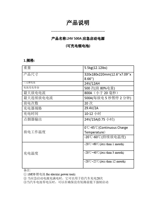
产品说明------------------------------------------------产品名称:24V 500A 应急启动电源(可充电锂电池)1.规格:① 18650锂电池for electric power tools②当应急启动电源充满电时,它可以用于给汽车充电20次③当汽车电池零电压时,可以在确保没有短路前提下强制启动2.产品特点:◆产品闲置寿命:大于两年.(无需每三个月充电一次)◆产品储存寿命:大于五年半.◆产品滥用损毁:(避免以下情况可以保证安全)加载短路. 加载反向24V,.加载电压超出29.4V ,加载反向29.4V◆原生电池加热设计使其可以在零下40摄氏度工作◆防坠落: 可以离地1米高处坠落◆环保: 和其他锂电产品一样无铅,汞或镉元素◆零伏强制启动:当汽车电池零伏是可以强制启动3.1 控制与显示:①八段数码显示②电池状态切换显示按钮(电压、温度、电量)③大灯开关按钮②&③零伏启动按钮④电源开关⑤充电接口⑥报警指示灯⑦USB 5V 直流输出接口⑧大灯⑨24V直流输出指示灯⑩24V 直流输出接口4·使用应急启动功能警告:保证启动对象只使用24V供电系统4.1 正确的使用步骤:4.1.1第一步: 将红色鱼夹(+)连接至电池正极(+),黑色鱼夹(-)连接至电池负极(-)。
然后再开启应急启动电源4.1.2 第二步:当你听到应急启动电源发出“I'm Ready”语音时尝试启动车辆。
备注:◆请勿每次尝试启动车辆超出5秒◆如果发动机无法正常启动,等待2分钟。
在等待期间语音提示“Please Wait”。
当听到语音提示“I'm Ready”时请再次尝试启动车辆。
4.1.3 在车辆发动机启动过后,断开连接的鱼夹,关闭应急启动电源并将鱼夹线重新缠绕起来4.2 在使用应急启动电源时你可能会听见警报声。
它有可能是以下错误操作引起的。
4.2.1 连接了 6V(摩托车电池)或者 12V(小汽车电池) 电池4.2.2 在鱼夹正极与负极之间出现极反4.2.3 如果你打开了应急启动电源并且没有连接车辆的情况下报警,这意味着应急启动电源本身存在故障,请停止使用应急启动电源。
Siemens 24V 4A输出高稳定电源说明书
53 mm
20 mm 20 mm 0 mm 0 mm 0.29 kg Yes
Snaps onto DIN rail EN 60715 35x7.5/15, direct mounting in different mounting positions 2 391 480 h Specifications at rated input voltage and ambient temperature +25 °C (unless otherwise specified)
Mechanics Connection technology Connections ● Supply input
● Output ● Auxiliary Width of the enclosure Height of the enclosure
5A overload capability 150% Iout rated typ. 200 ms 50 mV =^ 4 A 150% Iout rated typ. 200 ms
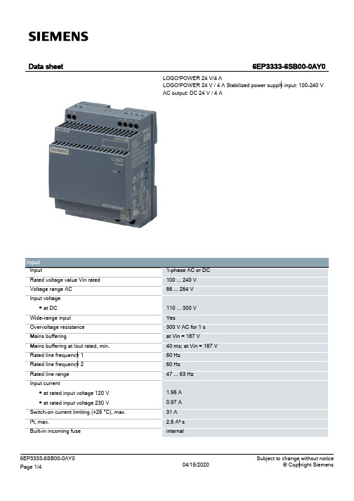
Data sheet
6EP3333-6SB00-0AY0
LOGБайду номын сангаас!POWER 24 V/4 A LOGO!POWER 24 V / 4 A Stabilized power supply input: 100-240 V AC output: DC 24 V / 4 A
Input Input Rated voltage value Vin rated Voltage range AC Input voltage ● at DC Wide-range input Overvoltage resistance Mains buffering Mains buffering at Iout rated, min. Rated line frequency 1 Rated line frequency 2 Rated line range Input current ● at rated input voltage 120 V ● at rated input voltage 230 V Switch-on current limiting (+25 °C), max. I²t, max. Built-in incoming fuse
- 1、下载文档前请自行甄别文档内容的完整性,平台不提供额外的编辑、内容补充、找答案等附加服务。
- 2、"仅部分预览"的文档,不可在线预览部分如存在完整性等问题,可反馈申请退款(可完整预览的文档不适用该条件!)。
- 3、如文档侵犯您的权益,请联系客服反馈,我们会尽快为您处理(人工客服工作时间:9:00-18:30)。
高稳定度直流电源设计
1
随着电力电子技术的发展,电力电子设备与人们工作、生活的关系日益密切,而电子设备都离不开可靠的电源。进入80年代计算机电源全面实现了开关电源化,率先完成计算机的电源换代。进入90年代开关电源相继进入各种电子、电器设备领域,程控交换机、通讯、电子检测设备电源、控制设备电源等都已广泛使用了开关电源,更促进了开关电源技术的迅速发展。开关电源是利用现代电力电子技术,控制开关晶体管开通和关断的时间比率,维持稳定输出电压的一种电源,开关电源一般由脉冲宽度调制(PWM)控制IC和MOSFET构成。开关电源和线性电源相比,其成本低、效率高、体积小、重量轻、电源输出组数多、极性可变等诸多优点,这些使得开关电源在现在生产和生活中得到广泛应用。
毕业设计说明书
高稳定度直流电源设计
专业
电气工程及其自动化
学生
班级
学号
指导教师
完成日期
高稳定度直流电源设计
摘 要:叙述开关电源的发展与现状,简要介绍开关电源的分类、发展动向及其意义;阐述了直流开关电源的结构和工作原理,对开关电源的主电路和控制回路进行设计:在主电路的输入回路中整流电路采用单相桥式整流,其中还设计了低通滤波电路、整流滤波电路和其他形式的滤波电路。此设计中功率转换电路采用半桥型DC/DC变换器,这是开关电源的核心部分,对此部分进行了重点分析和设计;控制电路采用电压型PWM控制,控制器采用开关电源集成控制器SG3525A,并对其特点、结构和工作原理作了简单介绍,对于系统的结构也进行了重点设计,并对其各个部分进行了元器件的选择和参数计算。其他部分还设计了保护电路和辅助电源电路。最后,用MATLAB仿真软件对主电路进行仿真测试,通过仿真测试结果对该直流电源设计的合理性进行判断,视其稳定性是否符合设计要求。
1.1 开关电源的发展与现状
1955年美国的科学家罗耶(G.H.Royer)首先研制成功了利用磁芯的饱和来进行自激震荡的晶体管直流变换器。此后,利用这一技术的各种形式的晶体管直流变换器不断地被研制和涌现出来,从而取代了早期采用的寿命短、可靠性差、转换效率低的旋转式和机械振子式换流设备,由于晶体管直流变换器中的功率晶体管工作在开关状态,所以由此而制的开关稳压电源输出组数多、极性可变、效率高、体积小、重量轻,因而被广泛应用于计算机、通信、航天、家电等领域中。
关键词:DC/DC变换器;PWM控制;SG3525A;MATLAB仿真
tability DCPowerSupply
Abstract:Describingthe development and current situation of switching power supply, switching power supply briefly introduced the classification, development trend and its significance;DC switching power supply described the structure and working principle of the switching power supply of the main circuit and control circuit design:In the main input loop circuit using single-phase rectifier bridge rectifier circuit, which also designed the low-pass filter circuit, the rectifier filter circuit, and other forms of filter circuit.This design, half-bridge type power conversion circuit using DC / DC converters, switching power supply which is the core of the focus of this part of the analysis and design;PWM control circuit with voltage control, switching power supply controller with integrated controller SG3525A, and its characteristics, structure and working principle is briefly introduced, the structure of the system carried on the key design and the various parts of the element of its Device selection and parameter calculations.Also designed to protect other parts of the circuit and the auxiliary power supply circuits.Finally, the main circuit simulation software MATLAB simulation test, the simulation results of the DC power to judge the rationality of the design, depending on whether it meets the design requirements of its stability.
开关稳压电源简称为开关电源(switching power supply),发展已有50余年,经历了三个重要发展阶段: