东芝CV300无机房系列(6E1M1838)调试手册
东芝电梯调试手册.
前言本使用说明书,就在进行无机房电梯SPACEL-UNI(CV300系列)控制装置(系统)的安装·保养·调整作业所必要的处理方法上进行了说明。
本说明书的内容的适用对象为具有控制系统基本知识的技术以及管理人员。
在实施各种作业时,必须事先熟读该说明书,根据上面记载的指示进行操作。
禁止进行说明书上记载内容以外的行为·操作。
请妥善保管好该说明书,谨请彻底管理。
控制系统操作时的注意事项系统调整程序书:6E1M1836试运转程序书:6E1M1837高速调整程序书:6E1M1838乘感调整程序书:6E1M1839故障判断・错误代号:6E1M1195调整维保指示书:6E1M1840安全上的注意事项为了防止对管理和使用者及他人造成危害和财产的损害与未然,安全正确地使用商品。
在装置的本体以及其使用说明书上,记载有重要的内容。
请将以下内容(表示·图记号)充分理解后,再阅读本文,并遵守其记载事项。
[表示的说明]※:所说的受伤是指不需要住院治疗或定期去医院看病的伤、烧伤、触电等。
[图记号的说明][本体警告表示标签的确认]一般禁止·注意事项为了维护制品·利用者·作业者的安全性,将作业时的注意事项例举于以下。
请掌握和遵守其内容。
电梯系统的不适当操作·作业是导致故障,坏损,灾害的起因 。
万一实施本说明书上记载的内容之外的行为,禁止的操作等,造成直接或间接的故障的场合,本公司将不负此责任,谨请谅解。
1) 在电梯控制盘上贴有PL 标签(制品安全标签)。
禁止进行违反PL 标签指示的事。
必须按照指示进行作业。
2) 没有指示禁止改造电梯控制盘。
将成为装置的误操作·发热·起火等的起因,有时也会给作业者自身带来危险。
3)在交换零部件之际,禁止纯正部件以外的使用(流用)。
必须使用指定用品。
4)在电梯控制盘方面,对于使用于调整保养的必要开关部以外的盘内部件,由于电源处于投入状态,因此禁止任意接触。
东芝 空调使用手册说明书

OWNER’S MANUAL1110650175AIR CONDITIONER (SPLIT TYPE)For general public useIndoor unitRAS-B10, 13, 16, 22N3KV2 Series RAS-M07, 24N3KV2 SeriesOutdoor unitRAS-10, 13, 16, 22N3AV2 Series RAS-M14GAV-E RAS-M18UAV-E RAS-3M18SAV-E RAS-4M23SAV-E RAS-3M26UAV-E RAS-4M27UAV-E RAS-5M34UAV-E1ENGLISHThe manufacturer shall not assume any liability for the damage caused by not observing the description of this manual.Store this owner’s manual in a location where it can be easily accessed when needed.Be sure to read this owner’s manual carefully before operating.It is recommended that maintenance be performed by a specialist when the unit has been operated for a long time.This appliance is not intended for use by person (including children) with reduced physical, sensory or mental capabilities, or lack of experience and knowledge, unless they have been given supervision or instruction concerning use of the appliance by a person responsible for their safety.Children should be supervised to ensure that they do not play with the appliance.Be sure to follow the precautions provided here to avoid safety risks.The symbols and their meanings are shown below.0 DANGER It indicates that incorrect use of this unit can result in a high possibility of severe injury(*1) or death.0 WARNING It indicates that incorrect use of this unit may cause severe injury or death.0 CAUTION It indicates that incorrect use of this unit may cause personal injury(*2), or property damage(*3).*1: A severe injury refers to blindness, injury, burns (hot or cold), electrical shock, bone fracture, or poisoning that leaves aftereffects and requires hospitalization or extended out-patient treatment.*2: Personal injury means a slight accident, burn, or electrical shock which does not require admission or repeated hospital treatment.*3: Property damage means greater damage which affects assets or resources.1Never do.4Beware of rotating parts5Electrical hazard. Contact with water will cause electric shock.Do NOT touch with wet hands. Always unplug when not in use.3Risk of fi nger injury2Always follow the instructions6Do not get the product wet0DANGER5Do not install, repair, open or remove the cover. It may expose you to dangerous voltages. Ask the dealership or the specialist to do this.5Turning off the power supply will not prevent potential electric shock.2The appliance shall be installed in accordance with national wiring regulation.2Means for disconnection from the supply having a contact separation of at least 3 mm in all poles must be incorporated in the fi xed wiring.1Do not place a spray can near the air outlet grille less than 1 m.The warm air from indoor and outdoor units may cause an explosion of the spray can.0WARNING2Installation must be requested from the supplying retail dealership or professional installation vendors. Installation requires special knowledge and skill. If customers install on their own, it can be a cause of fi re, electric shock, injury or water leakage.1Do not use any refrigerant different from the one specifi ed for complement or replacement. Otherwise, abnormally high pressure may be generated in the refrigeration cycle, which may result in a failure or explosion of the product or an injury to your body.1Do not disassemble, modify or relocate the unit by yourself. It may become the cause of fi re, electric shock, or water leakage. For repair or relocation, please request service from the supplying retail dealership.2When relocating or repairing the unit, please contact the supplying retail dealership. When there is a kink in the wiring, it may be the cause of electric shock or fi re.1Do not select a location for installation where fl ammable gas may leak. If there is any gas leakage or accumulation around the unit, it can be a cause of fi re.1Do not select a location for installation where there may be excessive water or humidity, such as a bathroom. Deterioration of insulation may be a cause of electric shock or fi re.2Earth work should be requested from the supplying retail dealership or professional vendors. Insuffi cient grounding work may be the cause of electric shock. Do not connect the earth wire to a gas pipe, water pipe, lightning conductor, or telephone earth wire.2You must use an independent power outlet for the power supply. If a power outlet other than the independent outlet is used, it may cause a fi re.2Check that the circuit breaker is installed correctly. If the circuit breaker is not properly installed, it may cause an electric shock. To check the installation method, please contact the supplying retail dealership or the professional vendor who installed the unit.2During an error (such as a burning odor, not cooling, or not warming), stop operating the unit and turn off the circuit breaker.Continuous operation may be a cause of fi re, or electric shock. Please request repair or service from the supplying retail dealership.1Do not turn ON/OFF the circuit breaker or operate buttons with a wet hand. It may be a cause of electric shock.1Do not insert any material (metal, paper, or water, etc) into the air outlet or air intake opening. Fan may be rotating at high speed inside or there are high voltage sections, which may cause an injury or electric shock.2When the air-conditioning unit does not cool or warm, there may be a leakage of refrigerant. Please consult the supplying retail dealership.The refrigerant used in the air-conditioning unit is safe. It will not leak under normal operating conditions but if it leaks into the room and contacts a heat source such as a heater, or stove, it may cause a harmful reaction.2When water or other foreign substances enter the internal parts, stop operating the unit immediately and turn off the circuit breaker.Operating the unit continuously may cause fi re or electric shock. Please contact the supplying retail dealership for repair.1Do not clean the inside of the air-conditioning unit yourself. Please request internal cleaning of the air-conditioning unit from the supplying retail dealership. Incorrect cleaning may cause breakage of resin parts or insulation defects of electrical parts, causing water leakage, electric shock or fi re. 1Do not damage or modify the power cable. Do not connect the cable midway, or use a multiple outlet extension cord that is shared by other devices.Failure to do so may cause fi re.1Do not place heavy objects on the power cable, expose it to heat, or pull it. To do so may cause electrical shock or fi re.1Do not expose your body directly to cool air for a long time.1Do not insert your fi nger or any article into the air inlet/outlet.0CAUTION2Ensure that drained water is discharged. When the discharging water process is not suffi cient, water may leak, causing water damage to furniture.To check that the installation method used is correct, please contact the supplying retail dealership or the professional vendor who installed the unit. 2If the indoor unit piping outlet is exposed due to relocation, close the opening, Touching internal electrical parts may cause injury or electric shock.1Do not wash the main air-conditioning unit with water. It may cause an electric shock.1Do not place any containers such as a vase containing fl uid on the unit. It might cause water to enter the unit and deteriorate the electrical insulation, causing an electric shock.2When using the unit in a closed room, or operating with other combustion appliances, make sure to open a window occasionally for ventilation.Insuffi cient ventilation may cause suffocation due to a lack of oxygen.1Do not use combustion appliances in the direct fl ow of the air from the air-conditioning unit. Poor combustion of a combustion appliance may cause suffocation.1Avoid operating for long periods in a high humidity environment (over 80%) such as with the windows or doors open. There may be condensation on the indoor unit and droplets may fall onto the furniture.2When the unit won’t be used for a long time, turn off the main switch or the circuit breaker.2At least once a year check if the mounting table of the outdoor unit is damaged or not. If a damaged state is ignored, the unit may fall or over-turn, causing an injury.1Stand on a sturdy ladder when attaching/detaching the front panel/air fi lter/air cleaning fi lter. Failure to do so may cause a fall or injury.1Do not stand on the outdoor unit or place anything on the unit. It may be the cause of injury due to falling or over-turning.Any damage to the unit may cause an electric shock or fi re.2Do not place anything around the outdoor unit or allow fallen leaves to accumulate around it. If there are fallen leaves, small animals could enter and contact internal electrical parts, causing a failure or fi re.1Do not place animals and plants in places where wind from the air-conditioning unit fl ows directly. It may have a negative infl uence on the animal or plant.1Do not use for special applications such as storage of food or animals, or to display plants, precision devices, or art objects.Do not use on ships or in other vehicles. It may cause a failure in the air-conditioning unit. In addition, it may damage these items.1Do not place other electrical appliances or furniture under the unit. Water droplets might fall, causing damage or failure.2When performing maintenance, you must stop operating the unit and turn off the circuit breaker. Since the fan inside may be rotating at high speed, it may cause an injury.2After the front panel/air fi lter is cleaned, wipe away any water and allow to dry. If water remains, it may cause an electric shock.1Once the front panel is removed, do not touch the metal parts (aluminum fi ns, etc.) of the unit. It may cause an injury.2When you hear thunder and there might be a lightning strike, stop operating the unit and disconnect the circuit breaker. If lightning strikes, it may cause a failure.• Batteries for remote control unit:- Should be inserted with correct polarity (+) and (-).- Should not be recharged.- Do not use batteries for which the “Recommended usage period” has expired.- Do not keep used batteries inside the remote control unit.- Do not mix different types of batteries, or mix new batteries with old ones.- Do not directly solder the batteries.- Do not short-circuit, disassemble, heat, or throw batteries into a fi re. If batteries are not disposed of correctly, they may burst or be the cause of fl uid leakage, resulting in burns or injuries. If touching the fl uid, wash thoroughly with water. If it touches devices, wipe off to avoid direct contact.- Do not place within reach of small children. If a battery is swallowed, consult a doctor immediately.• When you press CLOCK ●, CHECK ●, FILTER ● and RESET ● button, do not let any foreign substances enter and remain inside of the remote control.11. Open the air inlet grille and remove the air fi lters.2. Attach the fi1. Remove the slide cover.2. Insert 2 new batteries (AAA type) following the (+) and (–) positions.• Do not move the louver manually by others.• The louver may automation positioning by some operation mode.Note:• The provided Remote Controller is a wireless type, which also can be used as a wire. Please see “How to Connect The Remote Controller for Wired Operation”, located in installation instruction, in case of wired control is required.• In wire operation, remote controller will return to initial condition(PRESET, TIMER and CLOCK will return to initial condition) when user shutdown power supply of Air conditioner.REMOTE CONTROL4 1Infrared signal emitter 2Start/Stop button3Mode select button (MODE)4Temperature button (TEMP)5Fan speed button (FAN)6Swing louver button (SWING)7Set louver button (FIX)8On timer button (ON)9Off timer button (OFF)!Setup button (SET)"Clear button (CLR)#Memory and Preset button (PRESET)$One-Touch button (ONE-TOUCH)%High power button (Hi-POWER)&Economy button (ECO)(Quiet button (QUIET))Comfort sleep button (COMFORT SLEEP)~Filter reset button (FILTER)+Set clock button (CLOCK),Check button (CHECK)-Reset button (RESET)ONE-TOUCH5Press the “ONE-TOUCH” button for fully automated operation that iscustomized to the typical consumer preferences in your region of the world. The customized settings control temperature air fl ow strength, air fl ow direction and other settings to provide you alternate contact with “ONE-TOUCH” of the button. If you prefer other settings you can select from the many other operating functions of your Toshiba unit.AUTOMATIC OPERATION6To automatically select cooling or heating operation3. : Select AUTO, LOW , LOW+ , MED,MED+, or HIGH .3. : Select AUTO, LOW , LOW+ , MED ,MED+, or HIGH .DRY OPERATION8For dehumidi fi cation, a moderate cooling performance is controlled automatically. : Select Dry .Hi-POWER OPERATION9To automatically control room temperature and air fl ow for faster cooling or heating operation (except in DRY mode)ECO OPERATION10To automatically control room to save energy (except in DRY mode)Note:degree/hour for 2 hours (maximum 2 degrees increase).For heating operation the set temperature will decrease.Daily timer allows the user to set both the ON & OFF timers and will be activated on a daily basis.• During the every day timer is activating, both arrows (, ) are indicated.Note:• Keep the remote control in accessible transmission to the indoor unit; otherwise, the time lag of up to 15 minutes will occur.• The setting will be saved for the next same operation.PRESET OPERATION13Set your preferred operation for future use. The setting will be memorized by the unit for future operation (except air fl ow direction).1. Select your preferred operation.The PAUTO RESTART OPERATION14To automatically restart the air conditioner after the power failure (Power of the unit must be on.)Setting1. Press and hold the RESET button on the indoor unit for 3 seconds to set the operation. (3 beep sound and OPERATION lamp blink 5 time/sec for 5 seconds)2. Press and hold the RESET button on the indoor unit for 3 seconds to cancel the operation. (3 beep sound but OPERATION lamp does not blink)• In case of ON timer or OFF timer are set, AUTO RESTART OPERATION does not activate.To operate at super low fan speed for quiet operation (except in DRY mode)Note: U cooling due to low sound features.For comfortable sleep, automatically control air fl ow and automatically turn OFF.Note:1 degree/hour for 2 hours (maximum 2 degrees increase). For heatingQUIET OPERATION15COMFORT SLEEP OPERATION16SELF CLEANING OPERATION (COOL AND DRY OPERATION ONLY)1819REMOTE CONTROL A-B SELECTION21To separate using of remote control for each indoor unit in case of 2 air conditioners are installed nearly.Remote Control B Setup.1. Press RESET button on the indoor unit to turn the air conditioner ON.2. Point the remote control at the indoor unit.Control B is memorized.Note: 1. Repeat above step to reset Remote Control to be A. 2. Remote Control A has not “A” display. 3. Default setting of Remote Control from factory is A.Filter ResetFILTER lamp lights on; the fi lter must be cleaned.To turn off the lamp, push the RESET button on the indoor unit or the FILTER button on the remote control.Indoor Unit and Remote Control• Clean the indoor unit and the remote control with a wet cloth when needed.• No benzine, thinner, polishing powder or chemically-treated duster.To protect bad smell caused by the humidity in the indoor unit.automatically. This will reduce the moisture in the indoor unit.within 30 seconds.1. Three-minute protection feature: To prevent the unit from being activated for 3 minutes when suddenly restarted or switched to ON.2. Preheating operation: Warm up the unit for 5 minutes before blowing warm air.3. Warm air control: When the room temperature reaches the settemperature, the fan speed is automatically reduced and the outdoor unit will stop.4. Automatic defrosting: Fans will stop during defrost operation.5. Heating capacity: Heat is absorbed from outdoor and released into the room. When the outdoor temperature is too low, use anotherrecommended heating apparatus in combination with the air conditioner.6. Consideration for accumulated snow: Select the position for outdoor unit where it will not be subjected to snow drifts, accumulation of leaves or other seasonal debris.7. Some minor cracking sound may occur when unit operating. This is normal because the cracking sound may be caused by expansion/contraction of plastic. Note: Item 2 to 6 for Heating model Air conditioner operating conditionsES FR IT DE PT PL NLEN。
TOSHIBA E 中文手册
★在使用本产品之前请务必认真阅读本资料中的"操作及安全方面的注意事项"。
★本资料中所记载的技术信息仅用于说明产品代表性的动作、应用,而并非是使用时本公司及第三方的工业所有权及其他权利的保证或实施权的许诺。
★记载内容可能在不事先通知的情况下进行更改,使用时请向东芝电子管器件株式会社咨询。
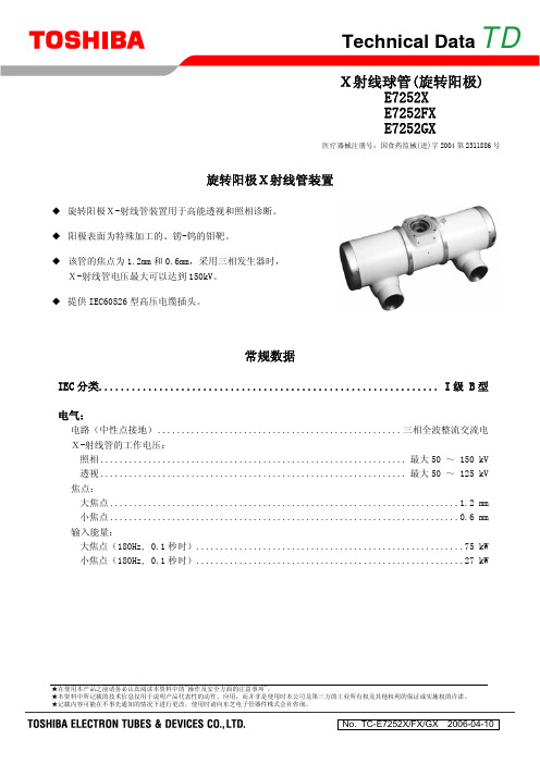
Technical Data TD旋转阳极X射线管装置◆ 旋转阳极X-射线管装置用于高能透视和照相诊断。
◆ 阳极表面为特殊加工的、铹-钨的钼靶。
◆ 该管的焦点为1.2mm 和0.6mm,采用三相发生器时,X-射线管电压最大可以达到150kV。
◆ 提供IEC60526型高压电缆插头。
常规数据IEC 分类..............................................................I 级 B 型电气:电路(中性点接地)...................................................三相全波整流交流电 X-射线管的工作电压:照相................................................................最大50 ~ 150 kV透视................................................................最大50 ~ 125 kV 焦点:大焦点.........................................................................1.2 mm 小焦点.........................................................................0.6 mm 输入能量:大焦点(180Hz, 0.1秒时)........................................................75 kW 小焦点(180Hz, 0.1秒时)........................................................27 kWX射线球管(旋转阳极)E7252X E7252FX E7252GX医疗器械注册号:国食药监械(进)字2004第2311886号E7252X, E7252FX, E7252GX发动机额定值:XS-AL状态 起动 运行电源 (Hz) 180 2)60 180 2)60输入功率 (W) 1100 910 83 83电压 (V) 220 130 60 40电流 (A) 5.7 7.8 1.6 2.3最小增速 1)(s) 1.2 0.8 - -电容器 (μF) 6 44 6 44最小制动时间 2)(s) 3 / 90 V (DC)定子阻抗公共端-主线圈之间的电阻值..................................................... 9.4 Ω 公共端-辅助线圈之间的电阻值...................................................28.3 ΩXS-R状态 起动 运行电源 (Hz) 180 3)50/60 180 3)50/60输入功率 (W) 2300 1450 300 80电压 (V) 460 240 130 58电流 (A) 5.4 6.5 2.0 1.5最小增速1)(s) 1.0 0.6 - -电容器 (μF) 3 24 3 24最小制动时间 2)(s) 1.5 / 90 V (DC) 3)定子阻抗公共端-主线圈之间的电阻值.................................................... 27.5 Ω 公共端-辅助线圈之间的电阻值...................................................58.0 Ω注: 1)从每分钟3000min-1(3600 min-1)的普通转速到每分钟10800转的高转速,提速时间 为所载提速时间(从0到高速)的2/3,其内容已在马达规格中载明。
东芝CV-150、320、300系列电梯故障代码
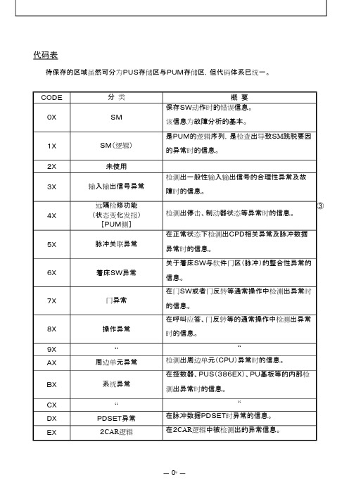
代码表待保存的区域虽然可分为PUS存储区与PUM存储区,但代码体系已统一。
CODE分类概要0XSM保存SW动作时的错误信息。
该信息为故障分析的基本。
1XSM(逻辑)是PUM的逻辑序列,是检查出导致SM跳脱要因的异常时的信息。
2X未使用3X输入输出信号异常检测出一般性输入输出信号的合理性异常及故障时的信息。
4X远隔检修功能(状态变化发报)[PUM侧]检测出停击、制动器状态等异常时的信息。
5X脉冲关联异常在正常状态下检测出CPD相关异常及脉冲数据异常时的信息。
6X着床SW异常关于着床SW与软件门区(脉冲)的整合性异常的信息。
7X门异常在门SW或者门反转等通常操作中检测出异常时的信息。
8X操作异常在呼叫应答、门反转等的通常操作中检测出异常时的信息。
9X““AX周边单元异常检测出周边单元(CPU)异常时的信息。
BX系统异常在控数器、PUS(386EX)、PU基板等的内部检测出异常时的信息。
CX““DXPDSET异常在脉冲数据PDSET时异常的信息。
EX2CAR逻辑在2CAR逻辑中被检测出的异常信息。
③①CODE内容或者原因数据3~801SMA已跳闸3=01 SSMAI02 LSMA4=轿厢位置层5、6=轿厢位置(脉冲数据)02SMB已跳闸3=01 SSMBI02 LSMB4=轿厢位置层5、6=轿厢位置(脉冲数据)03SMC已跳闸3=01 SSMCI02 LSMC4=轿厢位置层5、6=轿厢位置(脉冲数据)05SME已跳闸3=01 SSMEI02 LSME4=轿厢位置层5、6=轿厢位置(脉冲数据)06SM跳闸后,经过一段时间(NFLTDAT)之后,但仍无法到达平层,因此定为SMSI故障。
3=00 门区外01 门区内4=轿厢位置层5、6=轿厢位置(脉冲数据)07SM跳闸后,虽然3次尝试重新启动,但仍无法到达平层,或者在1小时之内2度检测出同一模式(SMA~SME),因此定为SMSI故障。
3=00 门区外01 门区内4=轿厢位置层5、6=轿厢位置(脉冲数据)CODE 内容数据3、4数据5~83=004=00:SSMAI通过PUS 跳闸SMA 5 ——— :未使用6=□IDTM :正常运行曲线模式7 ——— :未使用8=□跳脱NO :跳闸次数3=014=00:BOER 制动器异常开放 5 =6=□IDTM :正常运行曲线模式7 ——— :未使用8=□跳脱NO :跳闸次数3=024=00:PGERR马达PG 断线异常检测[CV200]5 ——— :未使用6=□IDTM :正常运行曲线模式7 ——— :未使用8=□跳脱NO :跳闸次数3=044=00:AMCER主回路接触器触点粘连检测5 =□6=□IDTM :正常运行曲线模式7 ——— :未使用8=□跳脱NO :跳闸次数3=084=00:MCCER 电流遮断异常检测5=□ 未使用6=□ IDTM :正常运行曲线模式7=— 未使用8=□ 跳脱NO :跳闸次数3=104=00:IREDTPUEXP100增量运动异常5=□ 未使用6=□ IDTM :正常运行曲线模式7=— 未使用8=□ 跳脱NO :跳闸次数3=404=00:ETSDT终端层减速异常(ETS ) 5 =7 =6=□IDTM :正常运行曲线模式8=□跳脱NO :跳闸次数3=204=00:LZNERLZN 整合性异常检测5=□6=□ IDTM :正常运行曲线模式7=— 未使用8=□ 跳脱NO :跳闸次数11SMA3=804=00:ETSERETS 用PG 断线异常检测5 ——— :未使用6=□IDTM :正常运行曲线模式7 ——— :未使用8=□跳脱NO:跳闸次数⑨⑨①③⑨⑩⑩⑩3=004=02 : SCER SCA粘连异常检测5 ——— :未使用6=□IDTM:正常运行曲线模式7 ——— :未使用8=□跳脱NO:跳闸次数3=004=04 : OSL低速时速度异常上升检测。
东芝CV180手册

C V 1 8 0调节舒适感的程序书使用说明书99年5月株式会社东芝© TOSHIBA Corporation ,1999.All Rights Reserved.希望在使用前,请详细阅读此使用说明书,完全理解其中内容后,再操作制品。
阅读后,请妥善保管说明书,以便随时可以使用。
在移置或转卖该制品时,必须将说明书与制品一起移交。
目录1.目的2.用于高速调节时的功能说明2.1 模拟输出的设定方法2.2 显示操作盘的轿厢呼叫记录方法3.电流传感器的零调4.特性曲线调节4.1 长程特性曲线调节4.2 短程特性曲线调节4.3 不合适时的对应方法1.目的2.用于高速调节时的功能说明2.1 模拟输出的设定方法CV180由于是速度控制,电流控制均为数字控制,因此即使直接连接波形记录仪,也不能看出现特性曲线等波形。
为此,可采用DB-MLT基板上的输出销DA1-DA4或PU-MLT基板上的输出销DA1-DA3测定D/A(数字/模拟)交换的信号。
(设定方法)(1) 从下一页的模拟输出用符号一览表中选择目的地址。
(2) 接着,将地址设定为E2PROM数据的DA__Adr□,DA__HL□。
DA__Adr□设定为16进制4位的地址。
DA__HL□,当地址是H侧[H]时,设定为0000;L侧[L]时,设定为00001。
(3) 将增益输入DAGain□,可决定输出波形的大小。
DAGain□的最上位的位是符号位,设定范围为8000(负的最大)-7FFF(正的最大)。
7FFF 可取增闪- +0.5。
(通常是4000(H)或C000(H))。
另外,根据需要,可设定移位数DAsft□(增益按2X调节。
如0001的话,为2倍。
)以及偏移(偏离)Daoff set□。
模拟输出=(设定输出数据)×(DAGain□)×2(DAset□)+DAoff set□(4)*因D/A变频器是12位,故下位时可进行模拟输出。
东芝CV300调试资料

东芝CV300调试资料
相关资料:
1、东芝CV330A电梯资料
2、东芝cv320a故障码调阅及故障代码
3、东芝CV320电梯系统调试
4、东芝电梯CV330A安装、维修资料汇总
5、东芝CV320电梯故障代码及如何查询故障
6、东芝电梯符号说明
7、东芝电梯UCMP 现场测试说明及操作步骤
8、东芝CV150查故障附:330A电梯井道学习、故障操作
9、东芝电梯维修新人培训教材
10、东芝超高速电梯维保技术
11、东芝-CV330A/335-OBM操作
本平台现在为电梯人创建了一个交流学习的平台,现有奥的斯、三菱、迅达、通力、日立、蒂森、东芝、富士达等电梯品牌微信交流群。
欢迎广大电梯技术爱好者的加入,本群禁止广告。
如有需要,请加小编微信号67172025,务必注明加群理由!。
东芝电型号说明及常用操作
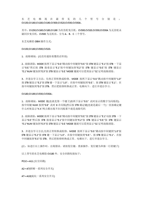
东芝电梯现在最常见的几个型号分别是:CV150;CV160;CV180;CV190;CV300;CV320;CV330;CV330A。
其中:CV150;CV160;CV180;CV190为有齿轮曳引机。
CV300;CV320;CV330;CV330A为无齿轮永磁同步曳引机。
CV300为无机房,分为A、B、C三个型号。
东芝电梯的OBM操作方式:CV150;CV160;CV300;CV320:1、故障调阅:(还没有通俗易懂的话形容)2、故障清除:MODE按两下显示“0.0.”跳动按中间键到“0.E.”按STB键显示“E.1”按STB一下显示“0.E.”然后按STB接着显示“E.1”按中间键加到“E.2”按STB键显示“0.E.”按STB键显示“E.1”NUM键加到“E.3”按STB键显示“0.E.”MODE键就可以看到显示“CL”证明故障清除。
3、井道自学习方法:先将正常转换成检修。
MODE按两下显示“0.0.”跳动按中间键到“1.0”按STB键显示“E.2”按STB键一下显示“1.0”,在按中间键按到“0.E.”,按STB键显示“E.1”,在按中间键按到“E.C”按STB。
然后把检修转换成正常。
电梯向下,进行井道自学习。
CV180;CV190;CV330;CV330A:1、故障调阅:MODE键(也就是第一个键子)按两下显示“0.0.” 此时显示的数字为闪烁的)。
按中间键NUM按到“0.8” 此时8在闪烁)然后按STB确定键(也就是最后一个)一直按确定键什么时候显示“X.X.”两点都出现不在闪烁那个就是故障代码2、故障清除:MODE按两下显示“0.0.”跳动按中间键到“0.E.”按STB键显示“E.1”动按STB一下显示“0.E.”然后按STB接着显示“E.1”按中间键加到“E.2”按STB键显示“0.E.”按STB键显示“E.1”NUM键加到“E.3”按STB键显示“0.E.”MODE键就可以看到显示“CL”证明故障清除。
300VF调试指南

FUNCTION:SETUP 3(设置)SET:PROFIL 2目的:用于设置“速度曲线发生器的安装参数”( THE PROFILE GENNERATOR INSTALLATION PARAMETERS)以上表示,依次按了“MODULE”、“2”、“3”、“2”键,之后服务器上显示:显示位00000000000000000000:安装参数的名称显示位111:安装参数旧的(现在的)设定值(十进制值)显示位222:安装参数新的设定值(十进制值),如果MCSS处于写保护状态(板上面的写保护开关处于DISABLE位置),则显示“…”,如果MCSS处于能写入状态(写保护开关处于ENABLE位置),用数字键输入相应安装参数的新的设定值后,按“ENTER”键就能输入新的设定值。
注意:出于安全的考虑,在MCSS系统正在工作时,(电梯正在运行中)是不能改变EEPROM内的安装参数的。
使用“GO ON”、“GO BACK”键就可以查看别的安装参数的设定值,必要时用以上方法就能设定新值。
MODULE:MCSS 2FUNCTION:SETUP 3(设置)SET:LANDING 3 (楼层)目的:用于根据大楼的实际情况设置各楼层“前后门的存在与否”(THE PROFILE GENNERATOR INSTALLATION PARAMETERS)以上表示,依次按了“MODULE”、“2”、“3”、“3”键,之后服务器上显示:显示位00:楼层数,比如“02”表示“3”楼,“00”表示“1”楼等显示位1 1:前门(Front door用Fr表示)和后门(用A1表示)的现行设定值,设定值为“1”表示存在,设定值为“0”表示不存在(或在次楼层由前门或后门,但用服务器软件为不允许开)显示位2 2:参数新的设定值。
如果MCSS处于写保护状态(板上面的写保护开关处于DISABLE位置),则显示“…”,如果MCSS处于能写入状态(写保护开关处于ENTER位置),用数字键输入相应参数的新的设定值后,按“ENTER”键就能输入新的设定值。
- 1、下载文档前请自行甄别文档内容的完整性,平台不提供额外的编辑、内容补充、找答案等附加服务。
- 2、"仅部分预览"的文档,不可在线预览部分如存在完整性等问题,可反馈申请退款(可完整预览的文档不适用该条件!)。
- 3、如文档侵犯您的权益,请联系客服反馈,我们会尽快为您处理(人工客服工作时间:9:00-18:30)。
请妥善保管好该说明书,谨请彻底管理。
使用说明书体系图
控制系统操作时的注意事项
系统调整程序书
:6E1M1836
试运转程序书
:6E1M1837
高速调整程序书 乘感调整程序书 故障判断・ 错误代号 调整维保指示书
:6E1M1838 :6E1M1839 :6E1M1195 :6E1M1840
1
TOSHIBA
另外,由于充电部(电容器·蓄电池等)的存在,即使断开电源,也有禁止一定时间接触的部位(依据 PL 标签的指 示),因此要按照指示进行作业。
5)禁止没有检查资格者(持有建筑基准法上规定的检查资格的人员,或者接受了指导具有同等机能的人员)的人员进 行维修保养·调整作业。
6)禁止带电作业。 有触电至死伤的危险。在配线作业之际,必须将动力用断路器(1S)以及照明用断路器(4S-1,2)打成 OFF,在确 认了没有供电的状态后,在进行施工。
8)应事先拔掉轿箱内的CNK3A。(无视称量装置的信号输出)
9)应事先FDS CUT。
7
TOSHIBA
38
3.在板功能
6E1M18
说明CV300B的调整所必要的操作方法。关于在板功能的详细内容、应参照「统一控制装置对应扶 梯在板功能使用说明书6E1M1150」。 (PUS,PUM,PUG共通)
3.1 在板构成構成
。
轿箱脉冲数据显示(0100脉冲显示时)
表示禁止(不允许做的事) 具体的禁止内容在图记号里及旁边的画,文章中指示出来。
表示强制。 具体的强制内容在图记号里及旁边的画,文章中指示出来。
在指定处请确认本体警告标签的贴付。 如果,标签遗失,由于污损而看不清楚时,请向本公司售后服务部门联系。
2
TOSHIBA
38
6E1M18
一般禁止·注意事项
为了维护制品·利用者·作业者的安全性,将作业时的注意事项例举于以下。请掌握和遵守其内容。 电梯系统的不适当操作·作业是导致故障,坏损,灾害的起因 。万一实施本说明书上记载的内容之外的行为,禁止的 操作等,造成直接或间接的故障的场合,本公司将不负此责任,谨请谅解。
3.1 在板构成・ ・
・・・・・・・・・・・・・・・・・・
3.2 扶梯的状态显示 ・ ・ ・ ・ ・ ・ ・ ・ ・ ・ ・ ・ ・ ・ ・ ・ ・ ・
3.3 脉冲显示功能 ・ ・ ・ ・ ・ ・ ・ ・ ・ ・ ・ ・ ・ ・ ・ ・ ・ ・ ・ ・
3.4 在板名指令功能・ ・ ・ ・ ・ ・ ・ ・ ・ ・ ・ ・ ・ ・ ・ ・ ・ ・ ・ ・ ・ ・
10)禁止不戴安全帽及穿着安全带进入电梯轿厢,并禁止在轿厢升降中从轿厢上的安全出口中钻出。 有冲突,落下的危险。
11)为便于一般利用者能触到,并在最上层乘场或乘场附近设置的副操纵盘上设置制动器开放装置和电源切断开关等, 在偏离副操纵盘的场合,必须安装副操纵盘的保护罩。 其中也包含防止由于误动作,恶作剧等造成的系统异常的发生。
6E1M18
5) 确认各层的厅门SW及 Gate 开关。
6) 确认 OVER BALANCE。(应按式样对应。) 根据需要,加减C/W的砣块。
7)设定以下负荷SW。
超载检测SW(1WLS)接点及调整方法
①1WLS接点 以往使用在1WLS的接点是a接点(NO)、但,在CV300B上使用b接点 (NC)。 应参照『称量装置安装工事用图』
东芝CV300无机房系列6E1M1838调试手冊
TOSHIBA
38
6E1M18
前言
本使用说明书,就在进行无机房电梯 SPACEL-UNI(CV300 系列)控制装置(系统)的安装·保养·调整作业所必要的处 理方法上进行了说明。
本说明书的内容的适用对象为具有控制系统基本知识的技术以及管理人员。
在实施各种作业时,必须事先熟读该说明书,根据上面记载的指示进行操作。禁止进行说明书上记载内容以外的行为·操 作。
8 8 8 9 9 11 11 12 13 15 17
5
TOSHIBA
38
1.目的
本书使用于扶梯试运转调试结束后的高速运转调整作业。 内容记载了基本作业和CV300B特有的项目。
2.高速运转准备
1) 所有的电闸都「OFF」。
2) 调整整顿、不应对运转造成任何影响。
3) 确认门是否被短路。短路的话就拆掉。
危険
事先短路门的话在门开的状态下运行是有危险的。高速调整时应必须拆掉门短路。 门短路一旦被拆掉,门不能动作的时候,确认门SW。 万一、当全层的门不得不提前进入到高速调整的时候,只需要短路其层的厅门门开关、不让 人接近那样进行处置。
6
TOSHIBA
38
4) 插入所有的连接器、并确认绝缘电阻以及是否有接错的问题。 确认方法见试运转调整步骤 6E1M1837 的「绝缘电阻试验」。
②1WLS调整方法 以往的1WLS的调整设定值、为了在相对于额定载重+5%的情况下也能动作,进行了相应的 调整、CV300B按下记对应。
相对于额定载重、+5% 或 +50kg 的小的值来动作那样进行调整。
设定例:
轿箱的额定载重
额定载重 +5%
额定载重 1WLS 设定值的允许值 +50 kg 设定值
630kg 800kg 1000 kg
3)为了防止控制盘内有异物的混入,请必须关闭外罩·盖子。这将是故障的起因。
4)出现异臭,过热,冒烟的场合,请立即切断电源。
5)在 HIB 副操纵盘围上电缆的场合,要充分注意光缆的弯曲和其他电线的固定。 根据电线的捆法,与门操纵盘的间隙很小,如果采用不合适的方法固定的话,门操纵盘会损伤。
6)在CV300B控制柜设置在井道背面或者侧面,轿厢和控制柜的间隙少于30mm~125mm。 轿顶点检时,由于异常声音和通芯确认等不能停止而必须从安全栏的框内探出身子的场合,设置安全开关,确认轿 厢不动之后在进行作业。 这时,要充分注意不要和控制柜接触。特别是从控制柜设置的下层上升的场合要注意不要碰到控制柜下部。 (轿顶的运转时请在不超出安全栏的框内的位置进行遥控。
危险
1) 在电梯控制盘上贴有 PL 标签(制品安全标签)。 禁止进行违反 PL 标签指示的事。必须按照指示进行作业。
2) 没有指示禁止改造电梯控制盘。 将成为装置的误操作·发热·起火等的起因,有时也会给作业者自身带来危险。
3)在交换零部件之际,禁止纯正部件以外的使用(流用)。必须使用指定用品。
4)在电梯控制盘方面,对于使用于调整保养的必要开关部以外的盘内部件,由于电源处于投入状态,因此禁止任意接 触。有触电的危险。
PU-200基板(右上部分) EL OBM CPD ●○○
LED1 LED2
MODE NUM STROBE OBM,EL,CPD PRS
: 模式选择按钮 : 数值选择按钮 : 模式・ 数值决定按钮 : 7seg 显示状态报知 LED :一旦按该按钮,即使处于任何状态也
会 E2ROM 写保护 ,返回到扶梯状 态显示模式 。
4
TOSHIBA
38
目录
6E1M18
1.目的・ ・ ・ ・ ・ ・ ・ ・ ・ ・ ・ ・ ・ ・ ・ ・ ・ ・ ・ ・ ・ ・ ・ ・ ・ ・ ・ ・ ・ ・ ・
6
2.高速运转・ ・ ・ ・ ・ ・ ・ ・ ・ ・ ・ ・ ・ ・ ・ ・ ・ ・ ・ ・ ・ ・ ・ ・ ・ ・ ・ ・ ・
6
3.在板功能機能・ ・ ・ ・ ・ ・ ・ ・ ・ ・ ・ ・ ・ ・ ・ ・ ・ ・ ・ ・ ・ ・ ・ ・ ・ ・
4.3 HCU地址设定 ・ ・ ・ ・ ・ ・ ・ ・ ・ ・ ・ ・ ・ ・ ・ ・ ・
4.4 HIB地址设定・ ・ ・ ・ ・ ・ ・ ・ ・ ・ ・ ・ ・ ・ ・ ・ ・ ・ ・ ・ ・ ・
4.5 机器的功能・ 操作确认・ ・ ・ ・ ・ ・ ・ ・ ・ ・ ・ ・ ・ ・ ・ ・ ・ ・ ・
7)禁止将安全回路,门回路作短路使用。(但不包括本体的作业时及安装调整手册所指示的项目) 紧急时各种保护不动作而造成的异常行走是非常危险的。
8)禁止事先不确认轿厢位置,用门非锁定钥匙开放轿门。这会造成在井道上落下而发生人员伤亡事故。
9)在进入轿厢上时,禁止在将安全开关(2KS)OFF,点检开关(INSS)ON,及顶部确保ห้องสมุดไป่ตู้SW(PTST)INS 之前乘入。另外, 禁止在乘入时有充分余额的位置上将轿厢停下之前乘入。 如果安全开关不 OFF,恐怕会有电梯突然起动而造成冲突,落下等危险。 如果点检开关不 ON,电梯可能会高速升降,会造成头部受伤。
注意
表示“如果进行误操作的话,有时可能导致人员受伤或仅仅发生物体的损伤”
※:所说的受伤是指不需要住院治疗或定期去医院看病的伤、烧伤、触电等。 [图记号的说明]
图记号
图记号的意思
[本体警告表示标签的确认]
表示危险。 具体的危险内容,在图记号里及旁边的画,文章中指示出来。
表示注意。 具体的注意内容在图记号里及旁边的画,文章中指示出来。
将门短路专用的键 SW 插入 DCP、从最右侧旋转到最左边、应拔除键。 ※只有安装调整人员才可以操作
① 拆掉控制柜操作面板的左下侧的短路用连接器 (CNDC)。
短路连接器 CNDC
检修开关 INPS
6E1M18
NO USE
DCP
解除
NOR
DC
DC
DCP 3 方向开关
②将键 SW 插入 DCP、 DC → NOR 。 另外,中点尚未使用、正常时是 NOR 、应事先拔出键。
12)在超出规格书上记载的周围环境条件等状态下,禁止进行作业。
13)在进行其他个别作业施工时,请遵守其他使用说明书上记载的禁止事项·注意事项。
3
TOSHIBA
38
注意
6E1M18
1)在故障时,在确认出错数据之前,请不要将 PAM 数据消掉。