ABB综合保护器REX521
REX521使用手册及调试技巧,依据多年使用,现场经验总结。

Protection Relay REX 521Operator’s Manual3REX 521Issued:29.11.2001Version:E/04.06.2004We reserve the right to change data without prior notice.Protection Relay Operator’s Manual Contents1.About this manual (5)1.1.Copyrights .....................................................................................51.2.Trademarks ...................................................................................51.3.General .........................................................................................51.4.Abbrevitations ...............................................................................61.5.Related documents .......................................................................61.6.Document revisions .. (7)2.Safety information (7)3.Introduction (8)3.1.REX 521 protection relay (8)4.Instructions (9)4.1.HMI features (9)4.1.1.Push-button functions (11)4.1.2.Selecting language (12)4.1.3.Passwords (13)4.1.4.Display backlight (13)4.1.5.Display contrast (13)4.1.6.Display test (14)4.1.7.Selecting primary values (14)4.1.8.Optically isolated serial communication port (14)4.2.Menu chart (15)4.2.1.Measurement menu (16)4.2.2.Event menu (17)4.2.3.Manual control (18)4.2.3.1.Local/Remote position selection (18)4.2.3.2.Controlling breaker (19)4.2.4.Setting parameters (21)4.2.5.Setting bit masks (21)4.3.Indication messages (22)4.3.1.Protection indications (22)4.3.2.Self-supervision (23)4.3.3.Condition monitoring indication (24)4.4.LED indicators (25)4.4.1.Green indication LED (READY) (25)4.4.2.Yellow indication LED (START) (25)4.4.3.Red indication LED (TRIP) (25)4.5.Alarm LEDs (26)4.5.1.Alarm LED 1-8 (26)1MRS 751107-MUMREX 521Protection Relay1MRS 751107-MUMOperator’s Manual5.Test mode (27)5.1.I/O test (27)5.2.IRF test (27)5.3.Function block test (28)6.Index (29)41MRS 751107-MUMProtection Relay Operator’s Manual REX 52151.About this manual 1.1.Copyrights The information in this document is subject to change without notice and should not be construed as a commitment by ABB Oy. ABB Oy assumes no responsibility for any errors that may appear in this document.In no event shall ABB Oy be liable for direct, indirect, special, incidental or consequential damages of any nature or kind arising from the use of this document, nor shall ABB Oy be liable for incidental or consequential damages arising from use of any software or hardware described in this document.This document and parts thereof must not be reproduced or copied without written permission from ABB Oy, and the contents thereof must not be imparted to a third party nor used for any unauthorized purpose.The software or hardware described in this document is furnished under a license and may be used, copied, or disclosed only in accordance with the terms of such license.Copyright © 2004 ABB Oy All rights reserved.1.2.Trademarks Brand and product names mentioned in this document are trademarks or registered trademarks of their respective companies.1.3.GeneralThe purpose of this manual is to provide the user with basic information on the protection relay REX 521 Revision E, and to especially focus on explaining the use of the human-machine interface (HMI).For information about the new features of the relay, refer to REX 521 Technical Reference Manual, General (see “Related documents” on page 6).61MRS 751107-MUM Protection Relay Operator’s Manual REX 5211.4.Abbrevitations 1.5.Related documents Manuals for the REX 521Parameter and event lists for the REX 521Tool-specific manuals CBFP Circuit-breaker failure protection CT Current transformer HMI Human-machine interface HSPO High-speed power output IRF Internal relay fault LCD Liquid chrystal display PO Power output RS Rogowski sensor SO Signalling output VD Voltage divider VT Voltage transformer •Technical Reference Manual, Standard Configurations 1MRS 751802-MUM •Technical Reference Manual, General 1MRS 751108-MUM •Installation Manual 1MRS 750526-MUM •Technical Descriptions of Functions (CD-ROM)1MRS 750889-MCD •Modbus Remote Communication Protocol for REX 521, Technical Description 1MRS 755017•DNP 3.0 Remote Communication Protocol for REF 54_ and REX 521, Technical Description 1MRS 755260•Parameter List for REX 5211MRS 751999-RTI •Event List for REX 5211MRS 752000-RTI •General Parameters for REX 5211MRS 752156-RTI •Interoperability List for REX 5211MRS 752157-RTI •CAP505 Installation and Commissioning Manual 1MRS 751273-MEN •CAP505 Operator’s Manual 1MRS 751709-MEN •CAP505 Protocol Mapping Tool, Operator’s Manual 1MRS 755277•Tools for Relays and Terminals, User’s Guide 1MRS 752008-MUM •CAP 501 Installation and Commissioning Manual 1MRS 751270-MEN •CAP 501 Operator’s Manual 1MRS 751271-MUM1MRS 751107-MUMProtection Relay Operator’s Manual REX 52171.6.Document revisions 1.7.Safety information Version Revision number Date History D 25.03.2004Document layout changed E 04.06.2004Pictures updated in tables, chapter 3.2.1.Changes in tables, chapters 3.4.1. and 3.5.1.Warning text added, chapter 4.1.REX 521Protection Relay1MRS 751107-MUMOperator’s Manual2. Introduction2.1.REX 521 protection relayThe protection relay REX 521 is designed for protection, control, measuring andsupervision in medium voltage networks. Typical applications include incoming andoutgoing feeders as well as substation protection. The protection relay is providedwith energizing inputs for conventional current and voltage transformers. Also ahardware version with inputs for current and voltage sensors is available.The protection relay is based on a multiprocessor environment. The HMI includingan LCD (liquid chrystal display) with different views makes the local use easy andinforms the user via indication messages. Modern technology is applied both inhardware and software solutions.The REX 521 is part of the substation automation concept for distributionautomation and extends the functionality and flexibility of the concept.81MRS 751107-MUM Protection RelayOperator’s Manual REX 52193. Instructions3.1.HMI features•Push-buttons for navigating, [C] Clear/Cancel and [E] Enter •Language selection•Setting values are protected by passwords•Display backlight•Display contrast•Display test•Selection of primary values•Optically isolated serial communication port•Three LED indicators•Eight programmable alarm LEDsREX 521Protection Relay1MRS 751107-MUMOperator’s Manual ArrayFig. 3.1.-1HMI front view1.Alarm LEDs2.LED indicator: Trip, CBFP3.LED indicator: Start, Block4.LED indicator: Ready, IRF, Test mode5.LCD6.Optical PC connector7.Navigation buttons8.Clear/Cancel9.Enter103.1.1.Push-button functionsThe HMI includes push-buttons for operating the protection relay.A quick touch on the arrow button up [↑] or down [↓] is interpreted as one stepupwards or downwards in a menu or as the minimum step up or down in settingmode of a parameter.•The cursor stops at the first and last rows in a menu; pressing the [↑] button at thefirst row or [↓] button in the last row is ignored.•If the [↑] or [↓] button is kept pressed, the menus are automatically scrolled fasterthan with single button pressings.Fig. 3.1.1.-1Push-buttonsThe table below gives a short explanation of the push-buttons and their functions.Table 3.1.1-1Push-button functions11Table 3.1.1-1Push-button functions3.1.2.Selecting languageFig. 3.1.2.-1Selecting language1.Select with [↓] and [→ ] buttons Configuration in the main menu,General in the group menu, Software in the subgroup menu andActive language in the parameter menu.2.Press the [E] button until the second row of the display starts flashing. Thenselect the desired language with [↓] and [↑] buttons.3.Confirm the selection by pressing the [E] button once more or cancel theselection by pressing the [C] button.After altering the language, the display menus are shown in the new language andthe selection is restored after a disconnection of the power supply.12Operator’s Manual3.1.3.PasswordsFig. 3.1.3.-1Password menusSetting values are protected by passwords. There are two different passwords, onefor protecting the HMI setting values and another for protecting settings throughserial communication.•The default value of the serial communication password is 001 and of the HMIpassword 999.•The HMI password is not active until it has been changed from the default value.After changing it, the relay prompts for password whenever the [E] button ispressed in the setting value menu. Once the right password has been given, itstays active until the display is returned to idle state by time-out. To disable theHMI password, change it back to the default value 999.•In case a password is forgotten, the HMI password can be viewed and changedvia serial communication.3.1.4.Display backlightThe backlight of the display is normally off. When a button on the HMI is pressed,the backlight turns on automatically and the panel is ready for further operations.•At power up, the backlight is also turned on during the display test.•After a time-out period (5 min), the backlight is automatically switched off ifthere has not been any activity on the panel.•When changing between Local/Remote mode by a digital input, the backlight isturned on for 10 seconds.3.1.5.Display contrastThe display contrast is temperature compensated, which means that the contrastautomatically adjusts itself with temperature to preserve readability.•To obtain optimal readability, the contrast of the display can be adjusted.Pressing simultaneously the [E] button and [↑] or [↓] button increases ordecreases the contrast.13Fig. 3.1.5.-1Adjusting display contrast•The display contrast may be adjusted anywhere in the menu structure except inthe setting menus where the [E] button is used for entering the setting mode.•The selected contrast value is stored in a non-volatile memory and thus, after anauxiliary power failure, the contrast is restored automatically.3.1.6.Display testUpon auxiliary voltage connection, the backlight is turned on and a short display testis run. This display test includes all the LEDs and the LCD. The LEDs are tested byturning them on simultaneously while the LCD shows two patterns so that all thepixels are activated. After the test, the display returns to normal state.•The display test can also be started manually by navigating toConfiguration\Display\Test display and then selectingTest display (refer to section “Menu chart” on page15).3.1.7.Selecting primary valuesThe setting values, input data and recorded values that are relative to some quantitycan be obtained directly in amperes and volts. For the relay to know how to convertbetween primary and per unit values, the setting values describing the measurementdevices (CT, VT, VD, RS) need to be properly set.1.Navigate to Configuration\Display\Primary values and selectPrimary values instead of the default Per unit values.2.Navigate to Configuration\Meas. devices and enter the data for allthe CTs and VTs, VDs and RSs that are in use in that particular hardware. Forinformation about setting the rated values for the protected unit and about thetechnical data of the measuring devices, refer to Technical Reference Manual,General (see “Related documents” on page6).3.1.8.Optically isolated serial communication portThe front panel of the protection relay is provided with an optical serialcommunication connector. The connector is used for programming the relay with aPC via a RS-232 cable, type 1MKC950001-1.143.2.Menu chartThe contents of the menu chart depend on the configuration of the relay. However,Fig. 3.2.-1An example of a menu chart structure15Operator’s Manual3.2.1.Measurement menuThe contents of the measurement menu depend on the relay configuration.If a measurement view is selected, it remains active after the time-out period. Thesame is true with the manual control view. From other views, the display reverts toidle mode at the same time as the backlight is switched off.•If energy measurements are present, accumulated values can be reset by pressingthe [C] button for 2 s.Table 3.2.1-1Measurement view16Table 3.2.1-1Measurement view (Continued)* The calculated thermal level of the device, maximum from the stator and the rotor.**Only available in configuration H083.2.2.Event menuThe event menu (Main menu\Measured values\Events) contains thefunction block name and the event in the same manner as the indication messages(see “Indication messages” on page22). The first view of the event menu shows theamount of events (maximum 50). The most recent event is stored on top of the list.When a certain event is selected, date and time of the event in question can be readby moving one step right with the [→ ] button. If the event in question is a trip eventand its data in the recorded data menu (Main menu\Protection\…\Recorded data1\…3\) has not been overwritten, it is possible to move directlyto the associated recorded data by moving right [→ ] again in the date and time view.Return to the event view with the [C] button or with the [← ] button, like in normalmenu navigation. When viewing recorded data, the return is directed to the eventsummary view (Main menu\Measured values\Events) if•the recorded data is overwritten, or•the original event is overwritten in the event list, or•the event list is cleared.These events are stored in the non-volatile memory, which means that they can alsebe seen after a disconnection of the power supply. When displayed, the event list canbe cleared by pressing the [C] button for 2 seconds.17Fig. 3.2.2.-1Event view3.2.3.Manual control3.2.3.1.Local/Remote position selectionThe control position can be changed in Control\Manual control\Local/Remote.•The control mode can be selected by pressing the [E] button and using the [↑] and[↓] buttons.•The [E] button confirms the selected mode and the [C] button cancels theselection and keeps the current mode.For password handling, refer to section “Passwords” on page13.Table 3.2.3.1-1Control positionsControl position DescriptionControl off Local and remote operations are inhibited. The current state of the objectis shown in the control menu.Local Object can be controlled from the HMI and the digital inputs. Remotecontrol is inhibited.Remote Object can be controlled via remote communication. Control from theHMI and digital inputs is inhibited and the object state is shown in thecontrol menu.External input The digital input programmed for selector Local/Remote is used forselecting between the local and remote modes. When selected the modewill be displayed as Local (ext.) or Remote (ext.) depending onthe digital input state.The selected control position remains the same during auxiliary power-off.When the local mode is selected, the character “L” is shown in the bottom-rightcorner of the HMI main view. However, if the language in the relay is other thanEnglish, the character that is shown in the display depends on the selected language. 183.2.3.2.Controlling breakerThe object control menu is in Control\Manual control\Control CB.Only the current position of the breaker is shown and no control is possible in remoteor control off mode. In local mode the state of the breaker is shown and the possibletarget states can be scrolled with [→ ] and [← ] buttons. Possible target states areopen and closed. When the desired target state is selected the object can be selectedby using the [E] button.Message =Preparing... can be briefly shown before the text=Are you sure? is displayed. The operation can then be confirmed with the [E]button and cancelled with the [C] button. If the operation is cancelled the text=Aborted is displayed for three seconds and then the current state of the breakeris shown. The same happens if the =Are you sure? has been displayed for 30seconds.Notice that an adjustable timeout in Control\General\Select timeoutrestricts the time between the object selection and the control request. If the timeoutis shorter than 30 seconds and it elapses before the operation is confirmed,controlling the object will not be possible before the object is selected again. If theoperation is confirmed, the appropriate transition text (=Opening... or=Closing...) is shown for at least four seconds after which the current state ofthe object is shown.19The current state of the interlocking of the object can prevent the select or executerequests. In that case the text =Interlocked is displayed for three seconds. Theattempted operation is cancelled and after the three seconds the current state of theC o n t r o l C B=O p e n. E=C l o s e=C l o s e d. E=O p e n=C l o s e d. E=C l o s eC o n t r o l C BC o n t r o l C Br e Y o u S u r e ?C o n t r o l C B=O p e n i n g ...Fig. 3.2.3.-1Manual controlTable 3.2.3-1Manual control messagesMessage MeaningAborted The current operation was aborted either by user or state change in object statusor timeout.Are you sure?Waiting for confirmation for the selected operation. [E] accepts it and [C] cancels it.Closed Object state is closed. Control is not possible due to remote or control off state.Closed. E=Close Object state is closed. [E] will close it.Closed. E=Open Object state is closed. [E] will open it.Closing...Object is being closed.External change Local/remote state controlled by digital inputs has changed. Only in external inputmode. Cancels current operation if any.Failed Executing the control request failed. The reason was not interlocking.Interlocked Selecting the object or executing the control request failed due to interlocking.Not allowed Selecting the object failed. The reason was not interlocking.Not local Attempted to control the object in remote or control off state.Open Object state is open. Control is not possible due to remote or control off state.Open. E=Close Object state is open. [E] will close it.Open. E=Open Object state is open. [E] will open it.Opening...Object is being opened.Preparing...Object is being selected.Undefined Object state is undefined. Control is not possible.Unresolved Object state is unknown.20Operator’s Manual 213.2.4.Setting parameters The setting parameters are listed in the CD-ROM Technical Descriptions of Functions (see “Related documents” on page 6).1.Navigate to the right parameter using the buttons [↑], [↓] and [→ ], [← ] and the menu chart structure as reference.2.Activate setting mode by pressing the [E] button.3.If the default HMI password has been changed, it is now prompted. To enter the valid password, change the active digit by pressing the buttons [← ] and [→ ], then set the digit value by pressing the buttons [↑] and [↓].4.Once the password has been entered, press the [E] button to confirm. Now the selected setting value starts flashing.5.Enter the new setting value using the buttons [↑], [↓] and [→ ], [←].6.Press the [E] button to confirm.7.If the new value is within the allowed limits, it is now stored in the non-volatile memory and restored after disconnection of power supply.8.If an illegal setting value is confirmed, a message in the display tells the user that the setting is out of range by showing the message Invalid value, and the previous parameter value remains unchanged.3.2.5.Setting bit masksEvent masks and switchgroups are presented as bit masks with a checksum. Most of the events can be included in or excluded from the event reporting by altering the bits of the event masks. Switchgroups are used for changing the connections of inputs and outputs to the relay function blocks.Fig. 3.2.5.-1Bit mask in setting modeWhen navigating in menus containing bit masks, only the checksum is shown. If setting mode is entered, the single bit presentation (bit 0, value 1, in the example above) appears in the rightmost lower corner of the display. The contents of the bit mask may be altered by entering single bit values. However, the new values are not valid until setting mode has been exited by pressing the [E] button.1.Navigate to the right parameter using the buttons [↑], [↓] and [→], [← ] and the menu chart structure as reference.2.Activate setting mode by pressing the [E] button.3.If the default HMI password has been changed, it is now prompted. To enter the valid password, change the active digit by pressing the buttons [← ] and [→ ], then set the digit value by pressing the buttons [↑] and [↓].4.Once the password has been entered, press the [E] button to confirm. Now the selected setting value starts flashing.5.Enter the new setting value using the buttons [↑], [↓] and [→ ], [← ].6.Press the [E] button to confirm.When entering single bit values, the bit to be edited may be shifted by pressing the[→ ] button when the cursor is located in the rightmost corner of the display. In thatway, the cursor does not have to be moved back and forth between the bit numberand the value during the setting period, thus simplifying the procedure.For information about the meaning of each event, refer to Event List for REX 521on the CD-ROM Technical Descriptions of Functions (see “Related documents” onpage6).3.3.Indication messagesThere are two different kinds of indication messages:•A text message together with a LED indication.This type of messages are related to information from the protection functionsand information concerning the condition of the protection relay (self-supervision).•A text message without a LED indication.This type of messages are related to condition monitoring, alarms and warningsor help texts appearing when certain display operations are performed.Indication messages have a certain priority. If different types of indications occursimultaneously, the message with the highest priority appears on the display.Priority order of the messages:1.Internal fault, CBFP2.Trip3.Start, Block4.Help messagesIndication messages may be cleared with the [C] button, until the display reverts tothe menu active before the events.Help messages are displayed when certain operations are done. For example, whenresetting output relays, events and registered values by pressing the [C] and [E]buttons for 5 s, a help text describing the operation is displayed at the same time.3.3.1.Protection indicationsWhen a protection function starts, the symbol of the protection function and the textSTART are displayed. The corresponding yellow LED indicator is also lit. In caseof three-phase or two-phase protection functions, the faulted phases are displayed aswell.Fig. 3.3.1.-1Indication of startIf a started protection function is blocked, the name of the function and the textBLOCK are displayed. Now, the yellow LED indicator is blinking.22Fig. 3.3.1.-2Indication of blockingIf a protection function trips, the name of the function and the text TRIP appear onthe display. The red LED indicator is lit. The faulted phases are displayed in thiscase.Should the protection function deliver a delayed trip for circuit-breaker failureprotection (CBFP), the red indicator starts blinking.Fig. 3.3.1.-3Indication of trip3.3.2.Self-supervisionThe protection relay is provided with an extensive self-supervision system. The self-supervision system handles run-time fault situations and informs the user aboutexisting faults over the display and the serial communication.When a fault has been detected, the green READY indicator starts blinking. At thesame time, the self-supervision (IRF) output relay is activated.Additionally, a fault indication text INTERNAL FAULT appears on the display andan event is generated.Fig. 3.3.2.-1Indication of faultThe fault indication has the highest priority and no other indication can overrun it.The fault indication text is displayed until it is cleared by pressing the [C] button.The green READY indicator continues blinking as long as the fault is present.Should the fault disappear after a reset, the indicator stops blinking and an event isgenerated over the serial communication. The self-supervision (IRF) output relay isreturned to its normal state.23243.3.3.Condition monitoring indicationIf the relay configuration includes condition monitoring functions that are not directly related to any protection function or to the internal relay condition,indication messages with the message SUPERV and an explanatory text appear if faults are found.Fig. 3.3.3.-1Condition monitoring indicationOperator’s Manual3.4.LED indicators3.4.1.Green indication LED (READY)3.4.2.Yellow indication LED (START)3.4.3.Red indication LED (TRIP)253.5.Alarm LEDs3.5.1.Alarm LED 1-8a.Valid only if the LED is not activated by the parameter Alarm LED States.b.The alarm can also be OFF if an auxiliary supply break has occurred. The state of the LED is thenpreserved and has to be acknowledged (cleared) from the main view.26274. Test modeDigital inputs, output relays and IRF relay may be tested by setting the parameter Test mode to Testing in the menu Main menu\Tests\General . When test mode is activated, the green READY indicator is blinking. For more information, refer to Technical Reference Manual, General (see “Related documents” on page 6).Test mode can be cancelled by setting the parameter to No test or by disconnecting the power supply.If the user does not cancel the test mode, it remains active and the Ready LED remains blinking.4.1.I/O test The picture below shows the menu used for digital input testing (Tests\Inputs ) in the hardware variant with nine digital inputs. The digits correspond to the inputs DI1...DI9, starting from the right side. Fig. 4.1.-1Digital input testing The following picture shows the menu used for output relay testing Tests\Outputs . Observe that the self-supervision relay is activated in another menu and is thus not included in this menu. The relays are activated in the order: SO, PO and HSPO, starting from the right side.Fig. 4.1.-2Output relay testing If the user forgets to cancel the test mode, it remains on and the Ready LED indicator remains flashing.4.2.IRF testThe IRF relay may be tested by activating the IRF relay in the menuMain menu\Tests\General\Activate IRF .4.3.Function block testThe outputs (Start and Trip) of a function block can be activated locally via the HMIor externally via serial communication. This is possible without setting the relay intest mode as described in “Test mode” on page27. The outputs are activated byusing control parameters of the function. For more information about the functions,refer to the CD-ROM Technical Descriptions of Functions (see “Related documents”on page6).285. IndexAAbout this manual (5)Alarm LEDs ..........................................................................................9, 261-8 (26)Modes (26)BBit masks (21)Altering contents (21)Breaker (19)Buttons (11)DDigital inputsTesting (27)DisplayAdjusting Contrast (13)Backlight (13)Contrast (13)Display test (14)Language (12)EEvent view (17)HH07 configurationMeasurement view (17)HMI features (9)IIndication messagesCondition monitoring (24)Green LED (25)Help messages (22)Internal fault (22)Protection indication (22)Self-supervision (23)Start, Block (22)Trip, CBFP (22)Introduction (8)IRF relayTesting (27)JJump (17)29。
高低压柜技术要求及技术规范
高压柜技术要求及规范一、有关技术标准本部分有关标准包括但不限于以下的IEC标准和相应的GB 标准。
若IEC标准和GB标准有不同之处,则应符合其中标准较高的一个。
1.1IEC62271-100 《交流高压断路器》1.2IEC-60044-1 《电流互感器》1.3IEC-60044-2《电压互感器》1.4IEC255《继电器》1.5IEC282《高压熔断器》1.6IEC62271-200 《1kV及以上52kV及以下交流金属封闭开关设备和控制设备》1.7IEC446《根据颜色和数字鉴别导线》1.8IEC529《外壳防护等级》1.9IEC60694 《高压开关设备标准的共用条款》1.10IEC-6009-4《交流系统用无间隙金属氧化物避雷器》1.11IEC-62271-102《高压交流隔离开关和接地开关》1.12GB156-2003标准电压1.13GB311.1-1993高压输变电设备的绝缘配合1.14GB311.6-83高电压试验技术1.15GB/T16927.1-16927.2-1997高电压试验技术1.16GB763-90交流高压电器在长期工作时的发热1.17GB2900.1-82电工名词术语基本名词术语1.18GB3309-89高压开关设备常温下的机械试验1.19GB7354-87局部放电测量1.20GB3906-2006 3.6~40.5kV交流金属封闭开关设备和控制设备1.21GB11022-2011高压开关设备通用技术条件1.22SD/T318-89高压开关柜闭锁装置技术条件1.23DL/T402-1999交流高压断路器订货技术条件1.24DL/T404-2007户内交流高压开关柜订货技术条件1.25DL/T486-2000交流高压隔离开关订货技术条件1.26DL/T403-200012-40.5kV高压真空断路器订货技术条件1.27DL/T539-93户内交流高压开关柜和元部件凝露及污秽试验技术条件1.28DL/T538-93高压带电显示装置技术条件1.29JB3855-199610kV户内高压真空断路器通用技术条件1.30DL/T593-1996高压开关设备的共用订货技术导则1.31国家电网公司生[2004]641号预防交流高压开关事故措施二、技术参数及规范2、工艺要求2.1高压开关柜的外壳和隔板应采用优质敷铝锌钢板经CNC机床加工和多重折弯之后以铆钉和螺丝栓接而成,钢板厚度2.5mm。
REX521操作说明书
3.说明 ................................................................................................... 11 3.1.HMI 的特点 ................................................................................................ 11 3.1.1.按钮功能 .......................................................................................... 13 3.1.2.更改语言 .......................................................................................... 14 3.1.2.1.使用按钮组合更改语言 ................................................................ 14 3.1.3.密码 ................................................................................................. 15 3.1.4.显示背光 .......................................................................................... 15 3.1.5.显示器对比度 .................................................................................. 15 3.1.6.显示器测试 ...................................................................................... 16 3.1.7.选择一次侧值 .................................................................................. 16 3.1.8.带光隔离的串行通讯端口 ................................................................ 16 3.2.菜单 ........................................................................................................... 16 3.2.1.测量菜单 .......................................................................................... 18 3.2.2.事件菜单 .......................................................................................... 19 3.2.3.手动控制 .......................................................................................... 19 3.2.3.1.就地 / 远方位置选择 ..................................................................... 19 3.2.3.2.控制断路器 ................................................................................... 20 3.2.4.整定参数 .......................................................................................... 21 3.2.5.整定掩码 .......................................................................................... 22 3.3.指示信息 .................................................................................................... 22 3.3.1.保护指示 .......................................................................................... 23 3.3.2.自检 ................................................................................................. 23
REX521_CN_new

© ABB Oy - 12 9 May 2005
REX 521 Feeder and Motor Protection
各种通讯规约
易于接入监控系统
REX521支持的通讯规约包括:
DNP 3.0 level 2 IEC 60870-5-103 Modbus LON SPA
© ABB Oy - 13 9 May 2005
© ABB Oy - 33 9 May 2005
REX 521 Feeder and Motor Protection
REX521输出继电器的接点能力
HSPO / PO SO / IRF 5 A 10 A 8 A 1/0.25/0.15 A
连续载流能力 0.5秒接通能力 3秒接通能力 在DC 48/110/220V,控 制回路时间常数 L/R<40ms下的遮断能力
© ABB Oy - 29 9 May 2005
定时限: 0.05— 300.00 S 同上
REX 521 Feeder and Motor Protection
REX521的整定范围-4
励磁涌流和电动机启动检测功能块 二次谐波比率:5—50% 启动电流: 0.1—5.0 X In 三相电流少于5% In ,且t >60 ms后,出现任一相大 于整定的启动电流,“电动机启动”动作。在大于整定的最 短脉宽下、当三相电流均少于90 %的整定启动电流且时间 大于150 ms时,“电动机启动”返回。 动作的最短脉冲宽度可在Control settings中整定, 其范围为:0—1000ms
© ABB Oy - 20 9 May 2005
REX 521 Feeder and Motor Protection
DI 输入回路及其输入菜单选择器
ABB继电器选型资料

选型手册
Product Catalog
目
录
发布:2005.09.12 状态:新稿 版本:A/2005.09.12 本公司保留数据修改权利·恕不另行通知
1
5
三 端子接线图
*) 功率方向 **) 典型接线 6
外部 跳闸 外部 合闸
隔离开关 Q1 合 隔离开关 Q1 分
隔离开关 Q2 合 隔离开关 Q2 分 隔离开关 Q3 合 隔离开关 Q3 分
REF 542plus 开关柜保护和测控装置
一概述
在中压开关柜的无论有无后台系统各种应用场合中,均能 使用数字式控制技术的解决方案。开关柜保护和测控装置 REF 542plus 就如同它的前一代产品 REF 542,集成了测 量、监视、保护、控制和自检等功能,同时拥有完善的通 讯规约,REF 542plus 能够方便地集成到 ABB 或其他第三 方后台系统中。上述功能和其他一些电能质量检测功能都 基于可编程环境中,新一代装置特别的灵活性和可扩展性 使得一个装置可实现所有的二次方案,甚至传统的方法无 法实现的方案,它都很容易实现。
开关量输入和输出接点数量
输入/输出接点数量 开关量输入接点 跳闸回路监视输出接点
REF 541 15 2
REF 543 25 2
REF 545 34 2
大容量输出接点(NO 单极)
0
大容量输出接点(NO 双极)
5
信号输出接点(NO)
2
2
3
9
11
2
4
信号输出接点(NO/NC)
5
P127产品区别于ABB西门子
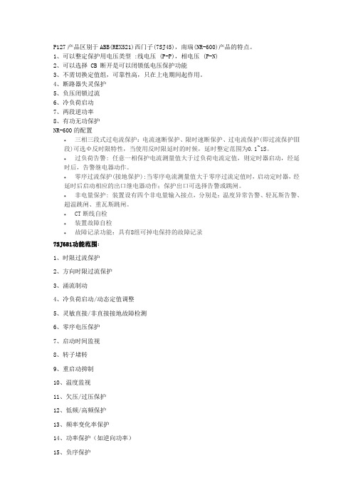
P127产品区别于ABB(REX521)西门子(7SJ45),南瑞(NR-600)产品的特点。
1、可以整定保护用电压类型 :线电压 (P-P),相电压 (P-N)2、可以选择 CB 断开是可以闭锁低电压保护功能3、不需切换定值组,可靠性高,只在上电期间起作用。
4、断路器失灵保护5、负压闭锁过流6、冷负荷启动7、两段逆功率8、有功无功保护NR-600的配置∙三相三段式过电流保护:电流速断保护、限时速断保护、过电流保护(即过流保护Ⅲ段)可选Φ反时限特性,当使用反时限延时的时候,延时整定范围为0.1~1S。
∙过负荷告警: 任意一相保护电流测量值大于过负荷电流定值,则定时器启动,经延时后,告警继电器动作。
∙零序过流保护(接地保护):当零序电流测量值大于零序过流定值时,启动定时器,经延时后启动相应的出口继电器动作;保护出口可选择告警或跳闸。
∙非电量保护: 装置设有四个非电量输入接点,分别是:温度异常告警、轻瓦斯告警、超温跳闸、重瓦斯跳闸。
∙CT断线自检∙装置故障自检∙故障记录功能:具有8组可掉电保持的故障记录7SJ681功能范围:1、时限过流保护2、方向时限过流保护3、涌流制动4、冷负荷启动/动态定值调整5、灵敏直接/非直接接地故障检测6、零序电压保护7、启动时间监视8、转子堵转9、重启动抑制10、温度监视11、欠压/过压保护12、低频/高频保护13、频率变化率保护14、功率保护(如逆向功率)15、负序保护16、相序监视17、自动重合闸(9次)18、低周减载19、低压减载控制功能/可编程逻辑:1、灵活配置的控制开关装置数量2、开关元件位置状态的图形显示3、可通过按键、二进制输入、DIGSI4h或SCADA控制4、利用CFC实现扩展的用户定义逻辑(如闭锁)监视功能:1、运行测量值U、I、P、Q、cosφ、f...2、电能测量值Wp、Wq3、二次回路监视功能4、熔丝故障监视5、跳闸及合闸回路监视6、最近8次故障录波应用:SIPROTEC4 7SJ68是一套兼具测控功能的微机保护装置,因此支持用户实施更高效的电网管理并保证对用户更可靠的供电。
ABB REX 521 馈线和电动机保护继电器 说明书
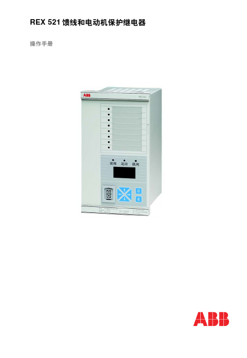
REX 521 馈线和电动机保护继电器操作手册如需购买此产品欢迎联系重庆艾利顿自动化联系人:余经理 联系电话:182********馈线和电动机保护继电器 操作手册3REX 5211MRS755714发布日期18.07.2005版本B/17.02.2006目录1.关于本手册 (7)1.1.本手册.................................................71.2.符号的使用.............................................71.3.相关文件...............................................71.4.文件修订版 (8)2.安全信息 (9)3.引言 (11)3.1.REX 521保护继电器 (11)4.说明 (13)4.1.HMI 的特点 (13)4.2.按钮功能 (15)4.2.1.选择语言 (16)4.2.1.1.使用按钮组合更改语言 (16)4.2.2.选择保护功能命名 (17)4.2.3.密码 (17)4.2.4.显示背光 (18)4.2.5.显示器对比度 (18)4.2.6.显示器测试 (18)4.2.7.选择一次侧值 (19)4.2.8.带光隔离的串行通讯端口 (19)4.3.菜单图 (20)4.3.1.测量菜单 (21)4.3.2.事件菜单 (22)4.3.3.手动控制 (23)4.3.3.1.就地/远方位置选择 (23)4.3.3.2.控制断路器 (24)4.3.4.整定参数 (26)4.3.5.整定掩码 (26)4.4.指示信息 (27)4.4.1.保护指示 (28)4.4.2.自检 (28)4.4.3.状态监视 (29)4.5.LED 指示灯 (30)4.5.1.绿色指示LED 就绪 (30)4.5.2.黄色指示LED 启动 (30)4.5.3.红色指示LED 跳闸 (31)4.5.4.告警LED1-8.....................................31版本馈线和电动机保护继电器报警通信端口如需购买此产品欢迎联系重庆艾利顿自动化联系人:余经理 联系电话:182********41MRS755714馈线和电动机保护继电器操作手册REX 521 5.测试模式 (33)5.1.I/O 测试 (33)5.2.IRF 测试 (34)5.3.功能模块测试 (34)6.缩写词 (35)7.索引 (37)装置内部故障测试如需购买此产品欢迎联系重庆艾利顿自动化联系人:余经理 联系电话:182********版权本文件中的信息如有更改恕不另行通知文件内容不应视为ABB Oy(芬兰)的承诺ABB Oy(芬兰)对本文件中可能出现的任何错误均不承担责任对于因使用本文件而产生的任何性质或类型的直接间接特殊偶然或必然损害以及因使用本文件中描述的软件或硬件而产生的偶然或必然损害ABB Oy(芬兰)均不承担任何责任未经ABB Oy(芬兰)的书面允许不得复制或复印本文件的任何部分不得将其内容告知第三方或进行未经授权的应用本文件中的软件或硬件受许可证保护只有在符合许可条款的情况下才能使用复制或公开版权所有© 2006 ABB Oy 保留所有权利商标ABB 是ABB集团的注册商标本文件中提到的所有其它品牌或产品名称可能是其所有者的商标或注册商标担保请向最近的ABB办事处咨询担保条款1MRS755714REX 5215馈线和电动机保护继电器操作手册如需购买此产品欢迎联系重庆艾利顿自动化联系人:余经理 联系电话:182********如需购买此产品欢迎联系重庆艾利顿自动化联系人:余经理 联系电话:182******** 61MRS755714REX 5217馈线和电动机保护继电器 操作手册1.关于本手册1.1.本手册本手册旨在向用户提供关于REX 521 馈线和电动机保护继电器的基本信息着重说明人机界面(HMI)的使用关于本继电器的新特点请参见REX 521技术参考手册概述(参见第7页相关文件)1.2.符号的使用本出版物包含的下列图标表示与安全相关的状况或其它重要信息尽管预警危险关系到人身伤害但必须明确在特定操作条件下运行损坏的设备将导致运行性能下降从而造成人身伤害或死亡因此须严格遵守所有预警和警告说明1.3.相关文件关于REX 521的手册电气预警图标表示存在可能导致电击的危险警告图标表示与本文中所讨论的概念相关的重要信息或预警信号表示存在可能导致软件瘫痪设备损坏或财产损失的危险信息图标提醒读者相关事实和条件•技术参考手册通用1MRS751108-MUM •技术参考手册标准配置1MRS751802-MUM •安装手册1MRS755713•功能模块技术说明(CD-ROM)1MRS750889-MCD •REX 521 Modbus远方通信协议技术说明1MRS755017•REF54_,RET54_和REX 521 DNP 3.0远方通信协议,技术说明1MRS755260如需购买此产品欢迎联系重庆艾利顿自动化联系人:余经理 联系电话:182********81MRS755714馈线和电动机保护继电器 操作手册REX 521REX 521参数和事件列表专用工具手册1.4.文件版本•REX 521参数列表1MRS751999-RTI •REX 521事件列表1MRS752000-RTI •REX 521一般参数1MRS752156-RTI •REX 521互操作性列表1MRS752157-RTI •CAP505安装和调试手册1MRS751273-MEN •CAP505操作手册1MRS751709-MEN •CAP505协议映射工具操作手册1MRS755277•继电器和终端装置用户指南1MRS752008-MUM •CAP501安装和调试手册1MRS751270-MEN •CAP501操作手册1MRS751271-MUM 版本日期历史A 18.07.2005创建文件B 17.02.2006由英文修订版1MR751107,rev.F 翻译而成如需购买此产品欢迎联系重庆艾利顿自动化联系人:余经理 联系电话:182********1MRS755714REX 5219馈线和电动机保护继电器操作手册2.安全信息即使切断辅助电源后在接线端子上也会出现危险电压不遵守上述说明可能导致死亡人身伤害或重大财产损失只允许由有资质的电工进行电气安装必须始终遵守国家和当地电气安全法规必须将该装置机架良好接地设备中包含有对静电放电敏感的元件因此应避免不必要地接触电子元件损坏装置背板上的封条将无权要求保修并不再确保正常的运行如需购买此产品欢迎联系重庆艾利顿自动化联系人:余经理 联系电话:182********如需购买此产品欢迎联系重庆艾利顿自动化联系人:余经理 联系电话:182******** 101MRS755714REX 52111馈线和电动机保护继电器操作手册3.引言3.1.REX 521 馈线和电动机保护继电器REX 521 馈线和电动机保护继电器设计用于在中压电力系统中进行保护控制测量和监控典型的应用包括进出馈线以及变电站保护保护继电器配有用于常规电流和电压互感器的交流量输入端此外该继电器还提供含电流和电压传感器输入的硬件版本该继电器基于多处理器环境HMI 包括一个LCD(液晶显示器)具有不同的视图便于本地使用并通过指示信息通知用户在硬件和软件解决方案中采用现代技术REX 521是用于配电自动控制中变电站自动控制概念的一部分进一步扩展了系统的功能和灵活性如需购买此产品欢迎联系重庆艾利顿自动化联系人:余经理 联系电话:182********如需购买此产品欢迎联系重庆艾利顿自动化联系人:余经理 联系电话:182******** 121MRS755714REX 52113馈线和电动机保护继电器操作手册4.说明4.1.HMI 的特点•导航按钮[C]清除/取消 和[E]确认/回车•语言选择•通过密码保护整定值•显示背光•可调节显示对比度•显示测试•选择一次侧值•含光隔离的串行通信端口•三个LED 指示灯•8个可编程报警LED如需购买此产品欢迎联系重庆艾利顿自动化联系人:余经理 联系电话:182********141MRS755714馈线和电动机保护继电器操作手册REX 521A060014图.4.1.-1HMI 正视图1.报警LED2.LED指示灯跳闸, CBFP 3.LED 指示灯启动, 闭锁4.LED指示灯准备就绪, IRF, 测试模式5.LCD6.光隔串行通信口7.导航按钮8.清除/取消9.确认/回车如需购买此产品欢迎联系重庆艾利顿自动化联系人:余经理 联系电话:182********1MRS755714REX 52115馈线和电动机保护继电器操作手册4.2.按钮功能HMI 含有用于操作继电器的按钮快速点击上移[↑]或下移[↓] 箭头按钮表示在菜单中前进一步或后退一步或表示在参数整定模式中最小的上移或下移•光标停止在菜单中的第一行和最后一行在第一行中按下[↑]按钮或在最后一行中按下[↓]按钮不起作用•如果按下[↑]或[↓]按钮不放那么菜单自动滚动的速度快于快速点击按钮的速度A060108图.4.2.-1按钮下表简要描述了按钮及其功能表 4.2.-1按钮功能上移/下移这些按钮用于• 在菜单中上移和下移• 输入新的整定值时滚动参数的有效数字左移/右移这些按钮用于• 在菜单中左移和右移• 输入新的整定值时更改参数的有效数字清除/取消这些按钮用于• 退出整定模式不保存• 从子菜单返回主菜单• 清除指示信息• 选择事件子菜单时清除事件(按下按钮长达2秒)选择主菜单时清除报警LED (按下按钮长达2秒)• 复归自保持输出继电器(按下按钮长达5秒)确认/回车该按钮用于• 用于进入参数的整定模式• 用于确认整定参数的新值• 配合使用[↑]或[↓]按钮调节显示对比度如需购买此产品欢迎联系重庆艾利顿自动化联系人:余经理 联系电话:182********161MRS755714馈线和电动机保护继电器操作手册REX 5214.2.1.选择语言图.4.2.1.-1选择语言1.通过[↓]和[→ ]按钮在主菜单中选择软件配置在组菜单中选择常规在子组菜单中选择软件以及在参数菜单中选择当前语言2.按下[E]按钮直到显示器的第二行开始闪烁然后用[↓]和[↑]按钮选择需要的语言3.再次按下[E]按钮确认选择或按下[C]按钮取消选择更改语言后菜单中的文字将用新的语言切断电源后恢复该选择4.2.1.1.使用按钮组合更改语言同时按住[← ]和[E]按钮5秒钟,将语言从英语更改为其它语言或从其它语言更改为英语该按钮组合可以在HMI菜单结构的任意位置使用所选的当前语言在继电器复位或电源断开后重新工作时将被恢复(清除/取消)&(确认/回车)同时按下这些按钮长达5秒• 复归自保持输出继电器事件以及保护功能已动作的记录值• 清除故障录波数据左移 & (确认/回车)同时按下两个按钮5秒• 将HMI 的语言从英语更改为其它语言或者从其它语言更改为英语表 4.2.-1按钮功能续++如需购买此产品欢迎联系重庆艾利顿自动化联系人:余经理 联系电话:182********1MRS755714REX 52117馈线和电动机保护继电器操作手册4.2.2.选择保护功能命名用户可以选择功能模块命名规则有ANSI 和IEC 两个选项可供使用它们分别遵循ANSI 标准和IEC标准保护功能命名规则导航至软件配置\显示\保护功能命名规则然后选择ANSI 或IEC所作的修改立即生效4.2.3.密码图.4.2.3.-1密码菜单通过密码保护整定值有两个不同的密码一个密码用于保护HMI整定值另一个密码用于通过串行通信保护整定值• 串行通信密码的缺省值为001HMI 的缺省密码为999•在更改缺省值之前HMI密码无效更改密码之后只要在整定值菜单中按下[E]按钮继电器就提示需要输入密码一旦给定正确的密码它将一直保持有效直到显示器由于超过时限而返回空闲状态要禁用HMI 密码应将其更改回缺省值999•如果忘记密码那么可以通过串行通信查看并更改HMI密码选择Chinese (中文)时一些IEC 保护功能名称将被译成中文如需购买此产品欢迎联系重庆艾利顿自动化联系人:余经理 联系电话:182********181MRS755714馈线和电动机保护继电器操作手册REX 5214.2.4.显示背光显示器的背光在正常情况下是关闭的按下HMI 上的按钮时背光将自动打开操作面板就绪等待下一步的操作•上电时在显示测试期间背光也打开•超过时限之后(5分钟)如果不操作面板那么背光自动关闭•通过开关量输入在就地/远方模式之间切换时背光打开长达10秒4.2.5.显示器对比度显示器对比度为温度补偿型这表示自动根据温度调节对比度保持可读性•要获取最佳可读性可调节显示器的对比度同时按下[E] 按钮和[↑]或[↓]按钮可增大或降低对比度A060114图.4.2.5.-1调节显示器对比度•可以在菜单的任何地方调节显示对比度但整定菜单除外该菜单中的[E]按钮用于进入整定模式•在非易失性记忆芯片中存储选中的对比度值当辅助电源产生故障后系统会自动恢复该对比度4.2.6.显示器测试连接辅助电源时背光打开系统将进行短时间的显示器测试该显示器测试包括所有LED 和LCD 在LCD 显示两个模式时同时打开所有LED 进行测试从而可以激活所有像素测试后显示器返回正常状态也可以通过导航到软件配置\显示\测试显示然后选择测试显示(参见第20页菜单图选择)如需购买此产品欢迎联系重庆艾利顿自动化联系人:余经理 联系电话:182********1MRS755714REX 52119馈线和电动机保护继电器操作手册4.2.7.选择一次侧值可直接获取与一些数量有关的整定值输入数据和记录值(单位为A 或V)为使继电器能够在一次侧值和二次侧值之间转换那么需要正确设置传感器或互感器(CTVTVD RS)的整定值1.导航到软件配置\显示\按一次侧值显示然后选择按一次值显示以代替按继电器额定电流倍数显示缺省值2.导航到软件配置\测量设备然后输入在每个互感器或传感器中使用的相关数据参见通用技术参考手册(参见第7页相关文件)以获取整定保护装置的额定值以及测量设备的技术数据信息4.2.8.带光隔离的串行通信端口保护继电器的前面板配有一个光隔离串行通信接口通过一条通信电缆型号为1MKC950001-2经RS-232端口与PC相连通过PC 对该继电器进行设置如需购买此产品欢迎联系重庆艾利顿自动化联系人:余经理 联系电话:182********201MRS755714馈线和电动机保护继电器操作手册REX 5214.3.菜单图菜单的内容取决于继电器不同版本的配置然而主菜单结构是不变的图.4.3.-1菜单结构图示例如需购买此产品欢迎联系重庆艾利顿自动化联系人:余经理 联系电话:182********1MRS755714REX 52121馈线和电动机保护继电器操作手册4.3.1.测量菜单测量菜单的内容取决于继电器不同版本的配置如果选择了测量菜单在超过时限之后该菜单仍然保持有效手动控制菜单也是如此对于其它菜单当背光关闭时显示器返回空闲模式•如果出现电能测量那么可通过按下[C]按钮达2秒复位累积值表 4.3.1-1测量菜单如需购买此产品欢迎联系重庆艾利顿自动化联系人:余经理 联系电话:182********热能级设备的计算热能级来自定子和转子的最大值4.3.2.事件菜单事件菜单主菜单\测量值\事件包含功能块名称和事件它们与指示信息(参见第27页指示信息)相同事件菜单的第一个窗口显示事件数量最多为50个在列表的顶部存储最近发生的事件当选择某个事件时可通过[→ ]按钮向右移动一步可以读取所述事件的日期和时间如果所述事件为跳闸事件并且没有覆盖记录数据菜单中的数据主菜单\保护\\录波数据1\3\那么可以在日期和时间窗口中右移[→ ]将其直接跳转到相关的已记录数据 在事件的第一行中用>大于号来表示这种可能性1通过[C]按钮或[← ]按钮返回事件菜单操作与标准菜单导航相同浏览已记录数据时(如果发生下述情况)直接返回到事件菜单主菜单\测量值\事件•覆盖记录数据•在事件列表中覆盖原始事件•清除事件列表事件均存储在非易失性芯片中这意味着切断电源后再送电时也可以浏览这些事件显示这些事件时可按下[C]按钮长达2秒清除事件列表表 4.3.1-1测量菜单1.选择Chinese(中文)时无效2223图.4.3.2.-1事件视图4.3.3.手动控制4.3.3.1.就地/远方位置选择可以在控制\手动控制\就地/远方中更改控制位置•可按下[E]按钮使用[↑]和[↓]按钮选择控制模式•[E]按钮确认选中模式[C] 按钮取消选择并保持当前模式 欲知密码设置信息请参见第7页相关文件.切断辅助电源期间选中的控制位置保持不变选择就地模式时在HMI主菜单的右下角显示字符L表 4.3.3.1-1控制位置控制位置描述关闭控制禁止就地和远方操作在控制菜单中显示操作对象的当前状态就地可通过HMI 和开关量输入控制操作对象禁止远方控制远方可通过远方通信控制操作对象禁止通过HMI 和开关量输入进行控制并在控制菜单中显示被控对象的状态外部输入用于给就地/远方切换被控开关量输入当选择使用时将由开关量输入的状态来决定为就地(外部)或远方(外部)244.3.3.2.控制断路器对象控制菜单位于控制\手动控制\控制CB中在远方模式或控制关闭模式中不能进行任何控制只显示断路器的当前状态在就地模式中显示断路器的状态并可通过[→ ] 和[← ]按钮滚动可能出现的目标状态可能目标状态为分或合当选择需要的目标状态后可使用[E]按钮选择对象信息=确定出现之前系统会简要显示消息=正在准备...然后可通过[E]按钮确认该操作通过[C]按钮取消该操作如果取消该操作那么信息=终止会显示3秒然后显示断路器的当前状态如果=确认?已经显示30秒也执行同样操作请注意控制\常规\选择超时中的可调节超时将限制对象选择和控制请求之间的时间如果超时时限小于30秒它会在确认操作之前结束那么将不能控制该对象如果确认操作那么相应的过渡信息=正在分闸...或=正在合闸...显示至少4秒之后系统会显示该对象的当前状态操作对象处于闭锁状态时不可以执行选择或执行请求此时信息=已联锁3秒可以取消准备进行的操作3秒后系统会显示对象的当前状态断路器延时合闸通过在就地HMI 使断路器合闸时出于安全考虑有时可能要求延迟实际合闸操作这样操作员可以有时间远离操作位置通过这种方式可避免在发生严重故障时导致人员受伤的危险 延时是可选和可调节的参数控制/常规/断路器合闸延时用于调节延时设置范围为 0 (30)秒参数的缺省值为0表示未激活延时功能仅可对合闸操作进行延时分闸操作通常立即执行当控制位置设为远方时不使用延时如果合闸延时激活并设为15秒则将显示倒计时信息15秒后合闸14秒后合闸1秒后合闸而不显示信息正在合闸...延时结束后断路器将合闸显示信息=合闸 E=分闸如果因联锁或其它原因不能合闸将中断控制序列并在LCD 上显示故障原因直至故障清除该消息之后将再次显示信息分闸 E=合闸25在延时倒计时期间按下任一个键或改变控制位置时(当控制位置为逻辑时)可取消延时合闸操作这两种情况下在LCD上显示信息终止此外当显示信息确认时按下[C]按钮也显示终止图.4.3.3.-1手动控制选择超时设置缺省值为30秒在LCD上显示信息确认时开始计时此时若按下[E]按钮便开始计算断路器合闸延时按下[E]按钮时继电器检查选择超时的剩余时间是否大于设定的断路器合闸延时时间如果不大于则在按下[E]按钮时在LCD 上显示信息=已终止表4.3.3-1手动控制信息信息含义终止可通过用户或对象状态中的状态更改或超时时限来终止当前的操作确认等待确认选中操作[E]表示确认[C]表示取消合闸合闸由于远方或控制关闭状态而不能进行控制合闸 E=合闸合闸[E]将进行合闸合闸 E=分闸合闸[E] 将进行分闸正在合闸正在合闸秒后合闸断路器合闸延时剩余时间(单位秒)外部变化修改由开关量输入控制的就地/远方状态已经改变系统只处于外部输入模式如有必要取消当前操作失败执行控制请求失败原因在于没有联锁264.3.4.整定参数在功能模块技术说明光盘中列出整定的参数(参见第7页相关文件)1.使用按钮[↑][↓]和[→ ][← ]并使用菜单结构图作为参考进入到正确的参数2.按下[E]按钮激活整定模式3.如果已经更改HMI缺省密码那么此时将出现提示信息用以下方式输入有效密码通过[← ]和[→ ]按钮更改有效位并通过[↑]和[↓]按钮改变数值4.一旦输入密码按下[E]按钮确认现在选中的整定值开始闪烁5.使用按钮[↑][↓]和[→ ][← ]输入新的整定值6.按下[E]按钮确认7.如果修改的整定值位于许可范围内那么系统会在非易失性芯片中存储该值并且在断电后恢复该值8.如果整定值无效那么继电器显示信息为无效值提示用户该整定值超出范围而先前的整定值不变4.3.5.整定掩码事件掩码和开关组以位掩码显示带有校验和通过更改事件掩码的位可以从事件报告中添加或删除大部分事件开关组用于更改继电器功能模块的输入和输出连接图.4.3.5.-1整定模式中的位掩码在包含位掩码的菜单中只显示校验和如果进入整定模式那么在显示器最右下角会显示位(在上述示例中为位0值1)可通过输入单位值来更改位掩码的内容然而新设定的值只有在按下[E]按钮并退出整定模式之后才有效已联锁由于联锁选择对象或执行控制请求失败不允许选择对象失败原因在于没有联锁不在就地状态尝试在远方或控制关闭状态下控制对象分闸分闸由于远方或控制关闭状态而不能进行控制分闸E=合闸分闸[E]将进行合闸分闸E=分闸分闸[E]将进行分闸正在分闸正在分闸正在准备正在选择对象不确认对象状态由于未定义而不确认不能进行控制未决定的对象状态未知表4.3.3-1手动控制信息续信息含义271.使用按钮[↑][↓]和[→][←]并使用菜单结构图作为参考进入到正确的参数2.按下[E]按钮激活整定模式3.如果已经更改HMI 缺省密码那么将弹出提示信息用以下方式输入有效密码通过按钮[← ]和[→ ]更改有效位并通过按钮[↑]和[↓]改变数值4.一旦输入密码按下[E]按钮确认现在选中的整定值开始闪烁5.使用按钮[↑][↓]和[→][← ]输入新的整定值6.按下[E]按钮确认输入位值时当光标位于显示器的最右角时可以按下[→ ]按钮移动要编辑的位这样在整定期间光标不必在位编号和值之间进行前后移动从而简化程序欲获取关于每个事件意义的信息请参见REX 521事例列表在功能模块技术说明光盘中(参见第7页相关文件)4.4.指示信息有两种不同的指示信息•带LED 指示的文本信息 该类信息是来自保护功能的信息以及与涉及保护继电器自身状态的信息 (自检)•无LED 指示的文本信息该类信息是关于状态监视报警以及预警或操作帮助有关的信息指示信息具有一定的优先级如果不同类型的指示同时产生那么在显示器上会出现具有最高优先级的信息信息的优先级次序为1.内部故障CBFP 2.跳闸3.启动闭锁4.帮助信息在显示器返回到发生事件之前的有效菜单之前可以通过[C]按钮清除指示信息完成某些操作时显示帮助信息比如通过按下[C]和[E]按钮长达5秒来复位输出继电器事件和记录值时会同时显示描述该操作的帮助信息4.4.1.保护指示保护启动时将会显示保护代码(或名称)和信息启动相应的黄色LED 指示灯也点亮如果为三相或两相保护功能也显示故障相28图.4.4.1.-1启动指示如果闭锁已启动的保护将显示被闭锁的保护代码(或名称)和信息闭锁此时黄色LED指示灯闪烁图.4.4.1.-2闭锁指示如果保护力能跳闸将显示动作的保护代码(或名称)和信息跳闸红色LED 指示灯点亮此时显示故障相如果是断路器失灵保护(CBFP)发送的延迟跳闸信号那么红色指示灯开始闪烁图.4.4.1.-3跳闸指示4.4.2.自检继电器装有完善的自检系统该自检系统检查出故障后在显示屏上或在后台系统通知用户检测到故障时绿色READY(就绪)指示灯开始闪烁与此同时系统会激活自检(IRF)输出继电器此外在显示屏上显示故障信息内部错误并产生相应的事件。
ABB REX 521切削工具操作指南说明书
—OPER ATING GUIDERelay Retrofit Program for REX 521 Cutting Tool Operating GuideCopyrightThis document and parts thereof must not be reproduced or copied without written permission from ABB, and the contents thereof must not be imparted to a third party, nor used for any unauthorized purpose.The software or hardware described in this document is furnished under a license and may be used, copied, or dis-closed only in accordance with the terms of such license.TrademarksABB and Relion are registered trademarks of the ABB Group. All other brand or product names mentioned in this document may be trademarks or registered trademarks of their respective holders.WarrantyPlease inquire about the terms of warranty from your nearest ABB representative./service/mediumvoltageDisclaimerThe data, examples and diagrams in this manual are included solely for the concept or product description and are not to be deemed as a statement of guaranteed properties. All persons responsible for applying the equipment ad-dressed in this manual must satisfy themselves that each intended application is suitable and acceptable, including that any applicable safety or other operational requirements are complied with. In particular, any risks in applications where a system failure and/or product failure would create a risk for harm to property or persons (including but not limited to personal injuries or death) shall be the sole responsibility of the person or entity applying the equipment, and those so responsible are hereby requested to ensure that all measures are taken to exclude or mitigate such risks.This product has been designed to be connected and communicate data and information via a network interface which should be connected to a secure network. It is the sole responsibility of the person or entity responsible for network administration to ensure a secure connection to the network and to take the necessary measures (such as, but not limited to, installation of firewalls, application of authentication measures, encryption of data, installation of anti virus programs, etc.) to protect the product and the network, its system and interface included, against anykind of security breaches, unauthorized access, interference, intrusion, leakage and/or theft of data or information. ABB is not liable for any such damages and/or losses.This document has been carefully checked by ABB but deviations cannot be completely ruled out. In case any errors are detected, the reader is kindly requested to notify the manufacturer. Other than under explicit contractual com-mitments, in no event shall ABB be responsible or liable for any loss or damage resulting from the useof this manual or the application of the equipment.ConformityThis product complies with the directive of the Council of the European Communities on the approximation of the laws of the Member States relating to electromagnetic compatibility (EMC Directive 2014/30/EU) and concerning electrical equipment for use within specified voltage limits (Low-voltage directive 2014/35/EU). This conformity is the result of tests conducted by ABB in accordance with the product standards of the IEC 60255 series.2Cu t t i n g To o l O p e r at ing G ui d eCu t t i n g To o l O p e r at ing G ui d e 31. Introduction1.1 Document revision history1.2 Related documentationBefore taking the cutting tool into use, familiarize yourself with the applicable documents. Depending on the cutting tool, see the appropriate document.Document revision/date History A/2018-05-02First releaseName of the documentDocument ID Relay Retrofit Program for REX 521 Product Guide1MRS758962Relay Retrofit Program for REX 521 Cutting Tool Safety Guide1MRS758975See the REX 521 and 615 series documentation for detailed technical information on the relays. Product series- and product-specific manuals can be downloaded from the ABB Website /mediumvoltage.1.3 SymbolsThe warning icon indicates the presence of a hazard which could result in personal injury.The caution icon indicates important information or warning related to the concept discussed in the text. It mightindicate the presence of a hazard which could result in corruption of software or damage to equipment or property.The information icon alerts the reader of important facts and conditions.The tip icon indicates advice on, for example, how to design your project or how to use a certain function.Although warning hazards are related to personal injury, it is necessary to understand that under certain operational condi-tions, operation of damaged equipment may result in degraded process performance leading to personal injury or death. Therefore, comply fully with all warning and caution notices.4 Cu t t i n g To o l O p e r at ing G ui d e2. Panel cut-out dimensionsThere are two options to widen the existing cut-out: To the left or to the right depending of the switchgear lay-out(free space on it).Figure 2: Left cutting Figure 3: Right cuttingFigure 1: REX521RRP with REF615 replacement relayA. 179 mm ± 1, new cut-out widthB. 136 mm ± 1, old cut-out widthC. 254 mm ± 1Cu t t i n g To o l O p e r at ing G ui d e 53. Cutting orderFigure 4 illustrates the cutting order on the front side of the switchgear door when the cutout is widened to the right.The left side cutting is symmetrical but to the left.Ensure the needed free space before starting the cutting procedure.If offcut gatherer is not used, protect the personnel and the switchgear panel from flying offcuts.It is recommended to use the gatherer. Figure 4 illus-trates the needed free space when the gatherer is in use. If there is not enough free space for the gatherer (see Figure 5 and Figure 6), the cutting head can be usedwithout the gatherer. However, safety concerns must be addressed. As the cutoffs may fly from the cutting head, make sure to pick up all the cutoffs and clean dust after the work is completed.Figure 4: Cutting order on the front side of the switchgear doorFigure 5: Cutting order to the leftFigure 6: Cutting order to the rightA. 179 mm, new cut-out widthB. 8 mmC. 254 mmD. 136 mm, old cut-out widthE. 58 mmF. 18 mmG. 100 mm1. Overlapping2. Space required for gatherer(symmetrical when cutting left side)6 Cu t t i n g To o l O p e r at ing G ui d e4. Cutting tool overviewA file (Figure 8) is needed for finishing the work before before installing REX521RRP.Note! The file is not included in the cutting tool kit.132456761. Cutting head2. Offcut gatherer (part of the cutting head)3. Vent lever4. Operating switch5. Power unit6. Battery7. Battery chargerFigure 7: Cutting tool kit componentsFigure 8: FileCu t t i n g To o l O p e r at ing G ui d e 75. Assembling the cutting tool1. Install the feed rod (2) to the power unit (1). Tighten the feed rod to the power unit so that all the feed rod threads are inside thepower unit.Figure 9: Assembling the cutting head1. Power unit2. Feed rod transmitting power to the punching head3. Punch4. Cutting head ID. When assembled correctly, the same text should appear in both the die and punch.5. Coil springs (2 pcs). The punch moves backwards to the starting position when the vent lever is pressed.6. Die7. Nut holding the cutting head parts together 8. Lock pin for locking the nut 9. Gatherer for collecting offcuts 10. Gatherer fixing screws (2pcs).11. Cutting head including eight parts111102349485678Cu t t i n g To o l O p e r at ing G ui d e The punch assembled to its place.2. Install the punch (3) to the feed rod (2). Notice the position of the REX 521 marking on the punch.3. Install the two coil springs (5) to their slots in thepunch (3).4. Install the die (6) to the feed rod (2). Ensure the correct die position with the marking in the die. Check that the coil springs (5) go to their slots indie.Cu t t i n g To o l O p e r at ing G ui d e 97. Ensure that the lock pin goes to its place.5. Add the nut (7) to the feed rod (2).6. Turn the nut so that the hole in the nut and the groove in the feed rod are aligned.Add the lock pin (8) to the hole in the nut.8. Add the gatherer (9) to the die (6) part of the cut-ting head with M6 socket screws (10).Use tightening torque of 4.2...5.2 Nm.The cutting tool kit includes a socket screw key (ISO2936-5) for the M6 screws.10Cu t t i n g To o l O p e r at ing G ui d e 9. Check and correct the gatherer alignment with the cutting head.Ready installed cutting head with the gatherer. After assembling the cutting head, insert the bat-tery to the power unit. The battery can be insertedfrom either side.Cu t t i n g To o l O p e r at ing G ui d e 116. PreparationsSee the Safety Guide before using the cutting tool.The cutting can be performed from the front or the back of the panel door. It is recommended to make the cut-out from the front side of the door panel to avoid sharp edges and ensuring smooth installation of the new replacement relay.The instructions in this document are based on making the cut-out from the front. The low-voltage compartment must be de-energized during the hole cutting procedure and installation of the new replacement relay.Ensure that there is enough space to operate the cutting tool in all intended directions. Check the space required by the new replacement relay. The cutting tool operation needs space around the cut-out.1. Remove the existing device.2. Release the signal connectors (not their wires).3. Release the wires from current/voltage connector.The used current/voltage connector wires arereused (in specified connector poles) with the newreplacing device.12 Cu t t i n g To o l O p e r at ing G ui d e6. Release the four fixing brackets.4. Release the protective ground wire.5. After the wires have been released, the whole de-vice can be released. Remove the four fixing bracketscrews.Cu t t i n g To o l O p e r at ing G ui d e 137. Operating the cutting tool on the left/right side edges1. Widen the existing cut-out to the left or to the right depending on the switchgear layout (freespace).For your safety, keep your hands on the powerunit, never on the cutting head.Beware of the sharp edges! Use safety gloves,protective glasses, hearing protectors and a hard hat.7. After releasing all the four fixing brackets, removethe device.2. Check that the cutting head is correctly installed. The marking REX 521 should be on the same side onthe punch and the die.14 Cu t t i n g To o l O p e r at ing G ui d e4. Push the operating switch as long as the sheetmetal part has been cut off.Be careful with the flinging offcuts, especiallyif the offcut gatherer is not used.Do not push the operating switch too long as it may cause maximum pressure in the power unit and result in additional force with vent lever use.3. Start the cutting procedure by pushing the guiding faces of the cutting head to the cut-out edges: to the top edge and to the right edgeside if the right edge widening/cutting is valid.For your safety, keep your hands on the powerunit, never on the cutting head.Beware of the sharp edges!5. Push the vent lever to ensure that the punch isreleased after each cut.In some cases, additional force is needed topush the vent lever.6. Make five cuts 1...5/6...10 one below the other (seefigure 4).Shake the cutting tool in between the cuttings 1...10 to arrange more space for the offcuts inside the gatherer.It is recommended to make overlapping cuts of 1...3 mm to avoid sharp edges in between the cuttingjunction points.Cu t t i n g To o l O p e r at ing G ui d e 15The fourth cut.7. For the fifth cut, push the cutting head, which is guiding the faces, firmly against the bottom sideedge.16 Cu t t i n g To o l O p e r at ing G ui d e2. Use a file to remove any sharp edges or burrs aroundthe cut-out area.3. Cover the relay compartment to avoid spreading dust.1. After each relay cut-out (ten separate cuttings), empty the offcut gatherer.For safety reasons remove the battery first.Ensure that no offcuts remain inside the switchgear if the offcut gatherer was not used.8. Finalizing the cutout4. Clean dust and any remaining offcuts.Cu t t i n g To o l O p e r at ing G ui d e 179. Finishing the work2. Push the new replacement relay firmly against the panel cut-out.1. It is advisable to coat bare surfaces, for example with cold galvanized compounds, in case of corrosive atmosphere.Install the new replacement relay.3. Add the four fixing brackets.4. Tighten all the four fixing bracket screws step bystep. Use tightening torque of 1.3...1.7 Nm.18 Cu t t i n g To o l O p e r at ing G ui d e5. Start the wiring work by connecting the safety ground wire.6. Connect the signal wire connectors. Fix female side wire connectors with their fixing screws to the male side connectors. Use a type PH 0 or PZ 0 (ISO 8764/2) screwdriver. Use tightening torque of 0.2Nm.8. Finish the work and close the door.7. Install the current and voltage wires. Only use screwdriver and insert bits for Phillips (PH 1) cross-recessed screws (M3.5). Use tightening torque of0.8...1.2 Nm.Cu t t i n g To o l O p e r at ing G ui d e 19—ABB Oy Distribution Solutions EP Service P.O. Box 503FI-65101 VAASA, Finland /service/mediumvoltageAdditional informationWe reserve the right to make technical changes or modify the contents of this document without prior notice. Withregard to purchase orders, the agreed par-ticulars shall prevail. ABB OY does not ac-cept any responsibility whatsoever for po-tential errors or possible lack of information in this document.We reserve all rights in this document and in the subject matter and illustrations con-tained therein. Any reproduction, disclo-sure to third parties orutilization of its contents – in whole or in parts – is forbidden without prior writ-ten consent of ABB OY.© Copyright 2018 ABB. All rights reserved. Specifications subject to change without notice.1M R S 758976 A © C o p y r i g h t 2018 A B B . A l l r i g h t s r e s e r v e d .。
ABB开关柜常见二次元件功耗
开关柜常见二次元件功耗
Date: 20080916 ≤2.5VA 2.5VA(AC) 1W(DC) 1.5 W(DC) 1.8VA(AC) 24VA 3RH14 27VA(AC) 24VA(AC) 4.6VA(AC) 3.5VA(AC) 3.2W(DC) <1W <6W GCE0990403P0100 270W 280W
额定二次电流=1A 额定二次电流=5A 额定二次电压=100V
S3-A-* S3-VD-* BA9054
ed by: Yong Liao
Approved by: Bernard
Rev. A 15 16 17 18 电流继电器 时间继电器 信号继电器 PLC BA9053 ETD-SL-1T-DTF MR11
储能电机
分闸脱扣器 26 NEW VD4 合闸脱扣器 合闸闭锁电磁铁 手车闭锁电磁铁 电机驱动手车 低电压脱扣器 Prepared by: Yong Liao
涌流持续时间≈100ms Approved by: Bernard
Rev. A
开关柜常见二次元件功耗
Date: 20080916 额定功率 储能电机 DC=5W AC=5VA 涌流持续时间≈100ms 储能时间6s 涌流持续时间≈45ms 涌流持续时间≈150ms 涌流持续时间≈150ms
UniGear ZS1 UniGear ZS3.2 短路电流≤31.5kA 涌流持续时间≈200ms 短路电流≤31.5kA 储能时间4~5s 短路电流=40kA 涌流持续时间≈200ms 短路电流=40kA 储能时间5~6s 涌流持续时间≈100ms 涌流持续时间≈100ms 涌流持续时间≈150ms 涌流持续时间≈150ms
地刀闭锁电磁铁/电缆室门电磁铁 电源:50HZ时 电源:60HZ时
ABB REX521 H50版本保护参数表
工作模式
□退出□定时限□A曲线□B曲线
76
电压定值
0.10...1.60×Un
77
时间定值
0.05...300.00s
78
反时限时间系数
0.05...1.00
79
过电压保护Ⅰ段,3U>>(59-2)
80
工作模式
□退出□定时限
81
电压定值
0.10...1.60×Un
82
时间定值
0.05...300.00s
57
工作模式
□退出□定时限□标准反时限
58
□极反时限□RI-反时限□RD-反时限
59
□甚反时限□长延时反时限
60
电流定值
0.05...40.00×In
61
定时限时间定值
0.05...300.0s
62
反时限时间系数
0.05...1.00
63
灵敏角ϕb
0°...90°
64
动作方向区
□正向□反向
65
接地保护
23
工作模式
□退出□定时限□瞬时
24
电流定值
0.10...12.00×In
25
时间定值
0.05...300.00s
26
方向零序电流保护Ⅲ段,I0>→(67N-1)
27
工作模式
□退出□定时限□标准反时限
28
□极反时限□甚反时限□长反时限
29
□RD-反时限
30
动作判据
□灵敏角与U0□灵敏角
31
□I0Sin/Cos与U0□I0Sin/Cos
ABB REX521 H50版本保护参数表
- 1、下载文档前请自行甄别文档内容的完整性,平台不提供额外的编辑、内容补充、找答案等附加服务。
- 2、"仅部分预览"的文档,不可在线预览部分如存在完整性等问题,可反馈申请退款(可完整预览的文档不适用该条件!)。
- 3、如文档侵犯您的权益,请联系客服反馈,我们会尽快为您处理(人工客服工作时间:9:00-18:30)。
6. Ordering information ............................................................. 42
4.1. Functional description .................................................................10 4.1.1. Parametrization ................................................................10 4.1.1.1. Local parametrization .........................................10 4.1.1.2. External parametrization ....................................10 4.1.1.3. Relay Setting Tool view ......................................11 4.1.2. Non-volatile memory ........................................................11 4.1.3. Real-time clock (RTC) ......................................................12 4.1.4. Auxiliary voltage ...............................................................12 4.1.4.1. Power supply versions .......................................12 4.1.4.2. Low auxiliary voltage indication ..........................13 4.1.5. Overtemperature indication ..............................................13 4.1.6. Analogue channels ..........................................................13 4.1.6.1. Setting the rated values for the protected unit ...13 4.1.6.2. Technical data of the measuring devices ...........14 4.1.7. Digital inputs ....................................................................16 4.1.7.1. Filtering of digital inputs .....................................16 4.1.7.2. Inversion of digital inputs ....................................17 4.1.8. Outputs ............................................................................17 4.1.8.1. High-speed power output (HSPO) .....................17 4.1.8.2. Single-pole power outputs (PO) .........................18 4.1.8.3. Signalling outputs (SO) ......................................19 4.1.9. Testing inputs and outputs ...............................................19 4.1.10.Trip-circuit supervision .....................................................20 4.1.11.Self-supervision ...............................................................21 4.1.11.1.Fault indication ...................................................23 4.1.11.2.Fault indication texts ..........................................23 4.1.12.Serial communication .......................................................24 4.1.12.1.Optical communication port on the rear panel ...24 4.1.12.2.Front panel optical connection for a PC .............25 4.1.12.3.The service pin located on the rear panel ..........25
Technical Reference Manual, General
We reserve the right to change data without prior notice.
REX 521
Contents
1. Safety information .....................................................................6
3
REX 521
Protection Relay
Technical Reference Manual, General
1MRS 751108-MUM
4.1.12.4.SPA bus ............................................................. 26 4.1.12.5.LON bus ............................................................ 27 4.1.12.6.IEC 60870-5-103 bus ........................................ 29 4.1.13.Time synchronization ....................................................... 30 4.1.14.Display panel (HMI) ......................................................... 30 4.1.15.Indication LEDs ..... 31 4.2. Design description ...................................................................... 31 4.2.1. Technical data ................................................................. 31 4.2.2. Terminal diagram of the REX 521: Basic ......................... 35 4.2.3. Terminal diagram of the REX 521: Medium ..................... 36 4.2.4. Terminal diagram of the REX 521: High .......................... 37 4.2.5. Terminal diagram of the REX 521: Sensor ...................... 38 4.2.6. Terminal connections ...................................................... 39
7. Revision history of the REX 521 ........................................... 43
7.1. Revision identification ................................................................. 43 7.2. Changes and additions to earlier released revision A ................ 43 7.3. Configuration, setting and SA system tools ................................ 43
REX 521 Protection Relay
Technical Reference Manual, General
1MRS 751108-MUM
Issued: 27.6.2001 Version: C/23.08.2002 Checked: ML Approved: MK