Century世特力转接头中文说明书
Cutler-Hammer ATC-400 控制转移开关快速操作指南说明书
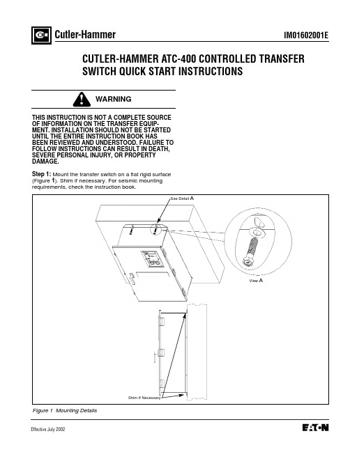
IM01602001EEffective July 2002Cutler-HammerCUTLER-HAMMER ATC-400 CONTROLLED TRANSFER SWITCH QUICK START INSTRUCTIONSTHIS INSTRUCTION IS NOT A COMPLETE SOURCE OF INFORMATION ON THE TRANSFER EQUIP-MENT. INSTALLATION SHOULD NOT BE STARTED UNTIL THE ENTIRE INSTRUCTION BOOK HASBEEN REVIEWED AND UNDERSTOOD. FAILURE TO FOLLOW INSTRUCTIONS CAN RESULT IN DEATH,SEVERE PERSONAL INJURY, OR PROPERTY DAMAGE.Step 1: Mount the transfer switch on a flat rigid surface (Figure 1). Shim if necessary. For seismic mountingrequirements, check the instruction book.Figure 1 Mounting DetailsShim If NecessaryView ASee Detail APage 2Effective 7/02Figure 2 300A, 3 Pole, Automatic Transfer Switch InteriorFuse Disconnect BlockEngine Start ContactsOptional Feature 37Fuse Disconnect BlockSource (S2) Power TerminalsPage 3Effective 7/02Tighten Cables Into TerminalsSee Detail BDetail BTypicalEngine Start Contacts(Red Terminals)Page 4Effective 7/02Figure 6 ATC-400 Logic (Utility Supplying Load)qqThe following lights must be ON:q Source 1 Available q Source 1 ConnectedPerform LED lamp test by depressing and holding. All LED’s should turn on.If not, contact factory for replacement.Page 5Effective 7/02Page 6Figure 7 ATC-400 (Rear View)Effective 7/02Page 7Effective 7/02qqqThe following lights must be ON:q Source 1 Availableq Source 1 Connectedq Source 2 AvailableThe following lights must be ON:q Source 1 Availableq Source 2 Availableq Source 2 ConnectedqqqIM01602001EPage 8Cutler-HammerPittsburgh, Pennsylvania U.S.A.Effective 7/02 (ISI)Style IM01602001E H01Printed in U.S.A.Step 10: ATH4/ATV4 Power Failure Test - Initiate a Load Test by simulating an actual power failure.(1) This should be done by opening the upstream breaker or fused disconnect switch.(2) If the ATS is Service Equipment Rated with no upstream disconnect, use the Normal Control Circuit Disconnect to simulate a power failure (Figure 10).This can be found in one of two places. The first would be located directly beside the normal breaker. The second would be located on the transformer panel/customer connection panel. The normal con- trol circuit disconnect is the disconnect markedNormal.The disconnect switch should be in the ON position for normal operation. Turning the switch to the OFF position will simulate a normal power out- age.Figure 10 Control Disconnect(3) The generator should start and the ATS should transfer to Emergency.(4) After transfer, close the upstream breaker, or close the Normal Control Circuit Disconnect. The TDEN timer should begin counting, and, when com- plete, the ATS should transfer to Normal. The En- gine Cooldown Timer should time out and shut the emergency power unit down.NOTICEWhile performing testing, if an undesired or undoc-umented result occurs, first contact the localGenset dealer. If the result is not corrected, contact the Cutler-Hammer Product Integrity Center at 1-800-210-6208.OFF PositionON Position。
Magnum Energy ME-PT1 插线转换器说明书

Part Number: 64-0025 Rev B1Magnum Energy, Inc.2211 West Casino Rd.Everett, WA, USA 98204IntroductionThe ME-PT1 (pigtail one-wire) adapter connects to Magnum’s Auto Generator Start (ME-AGS) controller to allow the connected generator to start when an external +12-volt DC supply is applied. This is useful for applications in which there is a need to automatically turn the generator on/off externally, either through a manually controlled switch or from an automatically controlled switching device.When +12-volts is supplied to this pigtail wire it causes the AGS controller to start and run the connected generator .Info: The high temperature start feature on the AGS is not available when using the ME-PT1. However , the low battery voltage start feature is still available.Installation/Setup – ME-AGS-N (Network Version)The following pertains to the ME-PT1 when connected to the ME-AGS-N.Info: Refer to the ME-AGS-N Owner’s Manual (64-0039) for installation, setup, and operation of the ME-AGS-N; and to the ME-RC (64-0003) or ME-ARC owner’s manuals (64-0030) for information on selecting/adjusting settings.InstallationTo install the ME-PT1, refer to Figure 1 and the steps below:1. Connect the red wire on the ME-PT1 adapter to a +12-volt DC externalswitching device (i.e., switch).2. Plug the ME-PT1 adapter into the REMOTE (purple) port on the ME-AGS-N.Info: The remote temperature sensor that comes with the ME-AGS-N (normally plugged into the AGS’s REMOTE port) is not used when a ME-PT1 is connected.SetupWhen using the ME-PT1 with the ME-AGS-N, con fi gure the ME-RC (or ME-ARC) to allow the ME-AGS-N to accept the external input from the ME-PT1.• Find the temperature start setting—depending on your remote: ME-RC(under AGS/04 Start Temp F menu), or ME-ARC (under SETUP/04E Gen Run Temp/Start menu). Then, select the Start=Ext Input setting.ME-PT1 to ME-AGS-N OperationThe type of external switch (i.e., “momentary” or “maintain”) connected to the ME-PT1 adapter determines how long the generator can run.ME-RCA. Using a momentary type switch: Pressing the switch causes the generator to run for the duration of a full run time cycle (as set in the AGS/03 Run Time Hour menu), and then stop.B. Using a maintain type switch: If the switch is set to ON, the generator continues to run until the switch is set to OFF . Once the switch is set to OFF , the generator will continue to run for the remaining duration of the current run time cycle (as set in the AGS/03 Run Time Hourmenu), and then stop.2© 2014 Magnum Energy, Inc.Figure 1, ME-PT1 to ME-AGS-N InstallationME-ARCA. Using a momentary type switch: Pressing the switch causes the generator to run for two minutes, and then stop.B. Using a maintain type switch: If the switch is set to ON, the generator continues to run until the switch is set to OFF . Once the switch is set to OFF , the generator will run for two minutes, and then stops.© 2014 Magnum Energy, Inc. 3Installation/Setup – ME-AGS-S (Standalone Version)The following pertains to the ME-PT1 when connected to the ME-AGS-S (Standalone Version) controller .Info: Other than the speci fi c installation and setup instructions listed below, refer to the ME-AGS-S Owner’s Manual (64-0004) for installation, setup, and operation of the ME-AGS-S.InstallationTo prepare the ME-AGS-S remote switch:1. Find the temperature sensor behind the remote switch’s front plate. It is asmall reddish looking device close to the metal front plate (see Figure 2).2. Use a pair of small wire cutters to cut open one side of the temperaturesensor wire (see Figure 3). Ensure the cut ends are not able to touch.To install the ME-PT1 (refer to the steps below and Figure 4):1. Plug a 6-conductor phone splitter into the REMOTE (purple) port on theME-AGS-S controller .2. Plug the ME-PT1 adapter into one of the phone splitter’s ports, andthen plug the remote switch—using its communications cable—into the phone splitter’s other port.3. Connect the red wire on the ME-PT1 adapter to a +12-volt DC externalswitching device (i.e., switch).Figure 2, Locating Sensor Figure 3, Sensor Cut OpenSetup1. On the ME-AGS-S, turn the START TEMP F adjustment clockwise to anytemperature position (DO NOT turn counterclockwise to OFF position).2. Press the remote switch on the ME-AGS-S to the up (ENABLE) position.ME-PT1 to ME-AGS-S OperationThe type of external switch (i.e., “maintain” or “momentary”) connected to the ME-PT1 adapter determines how long the generator can run.A. Using a momentary type switch: Pressing the switch causes the generator to run for the duration of the RUN TIME HOURS period, and then stop.B. Using a maintain type switch: If the switch is set to OFF , the generator stays off. If the switch is set to ON, the generator runs until the switch is set to OFF . Once the switch is set to OFF , the generator will not stop until the current RUN TIME HOURS cycle has been satis fi ed.EN ABLEFigure 4, ME-PT1 to ME-AGS-S Installation4 © 2014 Magnum Energy, Inc.。
电子产品EPM Serie 2-3W宽输入范围DC-DC转换器说明说明书

Selection Guide 2:1 2W OutputMODEL NUMBER INPUTVOLTAGE(VDC)OUTPUTVOLTAGE(VDC)OUTPUTCURRENT(mA)INPUT6CURRENT(mA) EFF(%)7ISOLATION8(VDC)PACKAGEFULLLOADNOLOADPM22-01(-3K) 4.5-9 3.3 500 465 50 71 1500(3000) H PM22-02(-3K) 4.5-9 5 400 555 50 72 1500(3000) H PM22-03(-3K) 4.5-9 9 222 519 50 77 1500(3000) H PM22-04(-3K) 4.5-9 12 150 480 50 75 1500(3000) H PM22-05(-3K) 4.5-9 15 120 456 50 79 1500(3000) H PM22-06(-3K) 9-18 3.3 500 205 30 67 1500(3000) H PM22-07(-3K) 9-18 5 400 219 20 76 1500(3000) H PM22-08(-3K) 9-18 9 222 225 20 74 1500(3000) H PM22-09(-3K) 9-18 12 168 209 20 80 1500(3000) H PM22-10(-3K) 9-18 15 133 209 20 80 1500(3000) H PM22-11(-3K) 9-18 24 83 213 20 78 1500(3000) H PM22-12 9-18 +/-5 +/-200 225 20 74 1500 H PM22-13 9-18 +/-12 +/-83 225 20 74 1500 H PM22-14 9-18 +/-15 +/-67 225 20 74 1500 H PM22-15(-3K) 18-36 3.3 500 93 12 74 1500(3000) H PM22-16(-3K) 18-36 5 400 110 12 76 1500(3000) H PM22-17(-3K) 18-36 9 222 111 13 75 1500(3000) H PM22-18(-3K) 18-36 12 168 104 11 80 1500(3000) H PM22-19(-3K) 18-36 15 133 105 11 79 1500(3000) H PM22-20(-3K) 18-36 24 83 107 11 78 1500(3000) H PM22-21 18-36 +/-5 +/-200 112 12 74 1500 H PM22-22 18-36 +/-12 +/-83 112 12 74 1500 H PM22-23 18-36 +/-15 +/-67 112 12 74 1500 H PM22-24(-3K) 36-75 3.3 500 46 8 75 1500(3000) H PM22-25(-3K) 36-75 5 400 56 8 74 1500(3000) H PM22-26(-3K) 36-75 9 222 55 8 75 1500(3000) H PM22-27(-3K) 36-75 12 168 51 8 82 1500(3000) H PM22-28(-3K) 36-75 15 133 51 8 82 1500(3000) H PM22-29(-3K) 36-75 24 83 54 8 77 1500(3000) H PM22-30 36-75 +/-5 +/-200 56 8 74 1500 H PM22-31 36-75 +/-12 +/-83 54 8 77 1500 H PM22-32 36-75 +/-15 +/-67 54 8 77 1500 H Note: Other input to output voltages may be available. Please contact factory.FOR EXAMPLE: PM22-12(H PACKAGE 2W SINGLE OUTPUT 1500VDC ISOLATION)PM22-11(-3K)(H PACKAGE 2W SINGLE OUTPUT 3000VDC ISOLATION)6NOMINAL INPUT VOLTAGE.7 NOMINAL INPUT VOLTAGE, FULL LOAD.Selection Guide 2:1 2W OutputMODEL NUMBERINPUTVOLTAGE(VDC)OUTPUTVOLTAGE(VDC)OUTPUTCURRENT(mA)INPUT9CURRENT(mA) EFF(%)10ISOLATIO N11(VDC)PACKAGEFULLLOADNOLOADPM22-33 4.5-9 3.3 500 465 50 71 1500 J PM22-34 4.5-9 5 400 555 50 72 1500 J PM22-35 4.5-9 9 222 519 50 77 1500 J PM22-36 4.5-9 12 150 500 50 72 1500 J PM22-37 4.5-9 15 120 500 50 72 1500 J PM22-389-18 3.3 500 205 30 67 1500 J PM22-399-18 5 400 219 20 76 1500 J PM22-409-18 9 222 225 20 74 1500 J PM22-419-18 12 168 213 20 78 1500 J PM22-429-18 15 133 213 20 78 1500 J PM22-439-18 24 83 213 20 78 1500 J PM22-4418-36 3.3 500 93 12 74 1500 J PM22-4518-36 5 400 112 12 74 1500 J PM22-4618-36 9 222 111 13 75 1500 J PM22-4718-36 12 168 107 11 78 1500 J PM22-4818-36 15 133 107 11 78 1500 J PM22-4918-36 24 83 107 11 78 1500 J PM22-5036-75 3.3 500 52 8 67 1500 J PM22-5136-75 5 400 56 8 74 1500 J PM22-5236-75 9 222 55 8 75 1500 J PM22-5336-75 12 168 51 8 82 1500 J PM22-5436-75 15 133 51 8 82 1500 J PM22-5536-75 24 83 54 8 77 1500 J Note: Other input to output voltages may be available. Please contact factory.9NOMINAL INPUT VOLTAGE.10 NOMINAL INPUT VOLTAGE, FULL LOAD.Selection Guide 4:1 2W OutputMODEL NUMBERINPUTVOLTAGE(VDC)OUTPUTVOLTAGE(VDC)OUTPUTCURRENT(mA)INPUT12CURRENT(mA) EFF(%)13ISOLATION14(VDC)PACKAGEFULLLOADNOLOADPM24-01(-3K) 9-36 3.3 500 205 30 70 1500(3000) H PM24-02(-3K) 9-36 5 400 222 20 74 1500(3000) H PM24-03(-3K) 9-36 9 222 225 20 74 1500(3000) H PM24-04(-3K) 9-36 12 165 213 20 78 1500(3000) H PM24-05(-3K) 9-36 15 133 213 20 78 1500(3000) H PM24-06(-3K) 9-36 24 83 213 20 78 1500(3000) H PM24-07 9-36 +/-15 +/-67 220 20 76 1500 H PM24-08(-3K) 18-75 3.3 500 98 12 70 1500(3000) H PM24-09(-3K) 18-75 5 400 112 12 74 1500(3000) H PM24-10(-3K) 18-75 9 222 112 13 74 1500(3000) H PM24-11(-3K) 18-75 12 165 107 11 78 1500(3000) H PM24-12(-3K) 18-75 15 133 107 11 78 1500(3000) H PM24-13(-3K) 18-75 24 83 107 11 78 1500(3000) H Note: Other input to output voltages may be available. Please contact factory.12NOMINAL INPUT VOLTAGE.13 NOMINAL INPUT VOLTAGE, FULL LOAD.Selection Guide (4) 2:1 3W OutputMODEL NUMBERINPUTVOLTAGE(VDC)OUTPUTVOLTAGE(VDC)OUTPUTCURRENT(mA)INPUT15CURRENT(mA) EFF(%)16ISOLATION17(VDC)PACKAGEFULLLOADNOLOADPM32-01(-3K) 4.5-9 3.3 700 641 100 72 1500(3000) H PM32-02(-3K) 4.5-9 5 600 800 100 75 1500(3000) H PM32-03(-3K) 4.5-9 9 333 778 100 77 1500(3000) H PM32-04(-3K) 4.5-9 12 250 779 100 77 1500(3000) H PM32-05(-3K) 4.5-9 15 200 779 100 77 1500(3000) H PM32-06 4.5-9 +/-5 +/-300 789 100 76 1500 H PM32-07 4.5-9 +/-12 +/-125 779 100 77 1500 H PM32-08 4.5-9 +/-15 +/-100 779 100 75 1500 H PM32-09(-3K) 9-18 3.3 700 263 45 73 1500(3000) H PM32-10(-3K) 9-18 5 600 336 45 74 1500(3000) H PM32-11(-3K) 9-18 9 333 320 45 78 1500(3000) H PM32-12(-3K) 9-18 12 250 320 45 78 1500(3000) H PM32-13(-3K) 9-18 15 200 310 45 81 1500(3000) H PM32-14 9-18 +/-5 +/-300 324 45 77 1500 H PM32-15 9-18 +/-12 +/-125 320 45 78 1500 H PM32-16 9-18 +/-15 +/-100 320 45 78 1500 H PM32-17(-3K) 18-36 3.3 700 128 20 75 1500(3000) H PM32-18(-3K) 18-36 5 600 162 20 77 1500(3000) H PM32-19(-3K) 18-36 9 333 152 20 82 1500(3000) H PM32-20(-3K) 18-36 12 250 158 20 79 1500(3000) H PM32-21(-3K) 18-36 15 200 154 20 81 1500(3000) H PM32-22 18-36 +/-5 +/-300 162 20 77 1500 H PM32-23 18-36 +/-12 +/-125 158 20 79 1500 H PM32-24 18-36 +/-15 +/-100 158 20 79 1500 H PM32-25(-3K) 36-75 3.3 700 66 12 73 1500(3000) H PM32-26(-3K) 36-75 5 600 81 12 77 1500(3000) H PM32-27(-3K) 36-75 9 333 80 12 78 1500(3000) H PM32-28(-3K) 36-75 12 250 79 12 79 1500(3000) H PM32-29(-3K) 36-75 15 200 76 12 82 1500(3000) H PM32-30(-3K) 36-75 24 125 79 12 79 1500(3000) H PM32-31 36-75 +/-5 +/-300 81 12 77 1500 H PM32-32 36-75 +/-12 +/-125 79 12 79 1500 H PM32-33 36-75 +/-15 +/-100 79 12 79 1500 H15NOMINAL INPUT VOLTAGE.16 NOMINAL INPUT VOLTAGE, FULL LOAD.Input Fuse Selection Guide4.5-9VINPUT VOLTAGE(VDC) 9-18V(9-36V) INPUT VOLTAGE(VDC) 18-36V(18-75V) INPUT VOLTAGE(VDC)36-75V INPUT VOLTAGE(VDC) 2000mA Slow-Blow Type1000mA Slow-Blow Type500mA Slow-Blow Type 200mA Slow-Blow TypeNote: Certain applications may require the installation of external fuse in front of the input.EPM 2-3 Watt Series Application Notes: EXTERNAL CAPACITANCE REQUIREMENTS:No external capacitance is required for operation of the EP 2-3 Watt series.To meet the reflected ripple requirements of the converter, an input impedance of less than 0.5 ohm from DC to 100KHz is required.External output capacitance is not required for operation, however it is recommended that 10uF tantalum and 0.1uF ceramic DC-DCCONVERTER+Vin-Vin+Vout-VoutOUTPUTINPUT。
Span F450T 立体转移援助器用户手册说明书

1Safety Instructions• FAILURE to use this device according toinstructions may cause serious injury.• NEVER attempt to transfer a patient or residentwhose weight exceeds the indicated maximumcapacity for this device or any accessory.• NEVER leave a patient unattended during transfer• DO NOT use without complete understanding ofsafe and correct operation• DO NOT use for the purpose of transportation overlong distances.• DO NOT use for the purpose of seating over longextended periods of time..3Product Features DESCRIPTION & APPLICATIONSThe Span F450T is a device from Span-America that represents a class of medical devices collectively referred to as standing transfer aids. The Span standing transfer aid is positioned between a traditional walkeror wheelchair and the common electric stand assist patient lift. TheF450T is a transfer assist unit which keeps the user actively engaged in the process. Transfer functions of all types are quick and require minimal caregiver assistance. Each unit is equipped with a crossbar where users can grasp and pull their self up into a standing position using their own strength. The padded split seats swing out allowing the user to stand place to form a secure and comfortable seat for the user to sit on for the remainder of the transfer.A patient or resident who qualifies to use the lift must have enoughleg and lower body strength to stand up and remain in the standing/ sitting position. Adequate arm strength is required if the patient must use present a potential for falling down will find the F450T a useful and safe transfer device. For patients who lack these requirements, a sit-to-stand lift such as the electric powered Span patient lift is preferred and recommended.The Span F450T standing transfer aid is suitable for the following types of transfers:• Bed to Chair/Wheelchair• Bed/Chair/Wheelchair to commode• Room to Room4235SPAN F450TMaximum CapacityMinimum Base Width Closed Base Width Base Height Unit Weight Maximum Base Width Base opens Minimum Seat Height Knee Pads / Shin Guards Optional Seat Locks Open Base Width Overall Height Overall Length Seat Width Optional Support Strap *Measured to the outside of each base leg with the base legs in the widest open position **Measured from the ground to the bottom of the seatUpgrade Base to 450 Lb 450 Lb / 205 Kg 26.826.7”4.5”71 Lb37”*Yes26.7”**YesYes37”*43.3”35.4”20”YesN/ASpecifications & Options4Assembly6Prior to assembly, unpack all parts from the shipping carton and check for any missing parts. Contact your dealer immediately if a part is missing.Factory assembled base with foot plate and castorsParts List1.Cross Bar x 22.Right Side Arm 3.Left Side Arm 4.Side Support Arm x 25.Knee Pad Support Bar 6.Knee Pad x 27.Seat x 2Tools & FastenersA18x Carriage bolt A22x Hex bolt A34x Hex screw A410x Washer A510x Lock washer A68x Lock nut A72x Plastic cap T11x Wrench T21x Allen keyease of assembly.Insert the kneepads into the support bar andsecure them in place with bolts and washers(A2 +A5 +A4) as indicated below.Cover the two bolt heads with black plasticcaps (A7) to complete kneepad assembly. Install the kneepad assembly between the twoside support arms as shown. Fasten in placewith four carriage bolts, nuts and washers.854Use the 4 hex screws (A3)Allen key (T2) to tightenthe completed assemblyInsert the two cross bars into the holes on the seat and handle bar support units.holes in the support units.Insert the kneepad side support assemblyinto the base slots and then insert the seatassembly into the kneepad and sidesupport assembly.Optional Seat Lock8Operating InstructionsMaintenance & Inspection • The Span F450T Standing Transfer Aid is a manual unit and therefore requires minimal maintenance on an ongoing basis. However to insure safety and proper use the following steps should be taken on a monthly basis.• Check all bolt/nut assemblies to make sure they are tight and no wear and tear is evident. Replace and tighten any worn assemblies prior to using the F450T.• Check the two seat assemblies to make sure they are not worn or damaged and that the bolts are tight. Replace any worn or damaged seat components before using the F450T.• Check the casters to make sure they are in working order and are secured firmly to the F450T. Replace any worn or damaged casters prior to using the F450T.1311WARRANTY POLICYSpan-America (“Span”) off ers a limited warranty on all patient lifts, slings and accessories to be free of defects in workmanship and product performance. This warranty extends only to the original purchaser and is non-transferrable. All warranty claims must be submitted by the authorized dealer or distributor who originally sold the product with proper proof of sale and serial number where applicable. Prior Return Authorization (RA) from Span is required for all warranty replacements. Span reserves the right to repair or replace only defective parts or accessories in lieu of a complete new patient lift. The repaired or replacement part shall be warranted for a period equal to the remainder of the warranty period of the defective part.Span does not provide advance replacements for warranty claims. For situations where an end user requires a replacement in advance and before a warranty item can be returned, dealer or distributor must purchase the replacement at full cost. All freight charges for the replacement are the sole responsibility of the dealer or distributor. When end user returns warranty item and item proves to be defective, Span will issue full credit for the replacement less freight charges.Product returned without RA number clearly marked on the package or product returned later than 30 days after authorization will be refused and returned at sender’s expense. Final disposition of warranty claims will be determined at the sole discretion of Span. Warranty claims will be denied for any of the following: product abuse or misuse, accidental or malicious damage, improper installation, product used with parts, components or accessories with quality or specifi cations incompatible with product, adulterated product, user neglect, failure to maintain and service product as specifi ed in the owner’s manual or care tag, serial number removed or defaced, or normal wear and tear.Span warrants the following products and components beginning from the purchase invoice date for the specifi ed time period: WARRANTY PERIOD PRODUCT OR COMPONENTThree (3) Years Patient lift frame or spreader barTwo (2) Years Actuator, control box, pendant, charger, weigh scale, Stand Aids, or casters excluding normal tread wearOne (1) Year Battery or hydraulic pumpSix (6) Months Reusable fabric slingsSingle Patient Specifi c slings are designed for limited use with one patient and may not be laundered. Span will replace any disposable sling found to have a manufacturing defect. Normal wear and tear will not be covered under warranty.This warranty expressly excludes wearable components including but not limited to foam parts and caster tread. Furthermore, this warranty is void and null for product that has not been purchased or paid for in full.RETURN GOODS POLICYPatient lifts may not be returned unless the wrong lift is shipped in error by Span or the lift is heavily damaged or defective out of the box. For all other items, purchaser may request a RA for purchased goods within thirty (30) days of purchase invoice date. All returns must be received by Span no later than thirty (30) days after authorization or the RA will be voided. Return package must be clearly marked with the RA number or the package may be refused and returned at sender’s expense. Patient lifts are subject to a minimum restocking fee of 25% or more. Please note that patient lifts being returned must be in the original carton with all parts, components and packing materials included. Failure to comply with this requirement will incur higher restocking fees or a rejection of the return. Slings, parts and accessories may only be returned if they have not been used. There are no exceptions to this provision.All freight charges are the sole responsibility of purchaser when any of the following occurs: (i) ordering error where an incorrect item is shipped in accordance with purchase order, (ii) an order is cancelled while in transit or (iii) delivery is refused by customer. Span reserves the right to issue credit amounts based on strict adherence to this policy.13。
Century 系列有线头戴器说明书

Today’s contact center and office professionals deserve technology that improves the quality of their everyday work-life. To work effectively, they require outstanding sound performance for natural, conversational communication and music/multimedia use and exceptional comfort for long hours of use with the ability to focus on the job in hand even in noisy environments. Naturally their headset must be extremely durable and able to withstand the toughest business environments. The Century™ Series of wired headsets delivers on all points.The wide range of 18 variant offers connectivity to a variety of devices such as desk phones, telecoil, PC, tablet and smartphone – for both fixed, flexible and mobile solutions. Designed for seamless interaction and full call control with all major Unified Communications platforms and phone solutions.The Century™ Series of wired headsets covers every situation with premium quality and style.BENEFITS & FEATURES–Outstanding sound for clear callsWith Sennheiser Voice Clarity for a naturallistening experience and ultra noise-cancelling microphone for perfect speechoutput–High-quality design crafted for perfectionBrushed aluminum and stainless steelcomponents and unibody headbandconstruction for maximum strength at stresspoints–Convenient and seamless call handling Proximity sensor (ANC variant) and in-line call control for easy call management–Easy to store and bring alongWith fold-flat ear cups and carry pouch –Exceptional wearing comfort Leatherette ear pads for allday comfort and powerful soundSee more at /century With its 18 variants, the Century™ Series offers connectivity to a variety of devices. See all headset variants and connectivity options in the table overview on page 3Quality speakslouder than wordsTELECOILProduct DataGeneral Data Wearing StyleHeadband – single and double sided variants. See table overview ColorBlack with silver Headset weightSingle sided 59 g / 2.1 oz Double-sided 95 g / 3.4 oz Double-sided 110 g / 3.88 oz (SC 660 ANC USB)AudioSennheiser Voice ClarityFor a clear and natural listening experienceMicrophoneUltra noise-cancelling microphone for optimal speech transmission Microphone frequency range 150 – 6,800 Hz (Wideband)Speaker typeHigh-quality neodymium magnet speaker for outstanding audio quality Speaker frequency response – multimedia 50 - 18,000 Hz50 - 12,000 Hz (SC 638 / SC 668)Sound pressureLimited by ActiveGard®: Max. 103 dB via EDMax. 110 dB via ED (SC 638 / SC 668) Max. 118 dB via USB/USB-C Max. 118 dB via 3.5 mm jack Made for communication & multimedia*Sound enhancement profiles adjust automatically for optimalcommunication or multimedia use Enhanced music audio performance**For a richer audio experience when listening to musicActive Noise Cancellation***For enhanced noise reduction in open offices. Can be turned on/offHearing Protection ActiveGard® TechnologyProtects users against acoustic injury caused by sudden sound burst on the lineEU Noise at Work limiter*/****Enhanced audio protectionpreventing listening fatigue, average 85 dB over a work dayEasy Call Management In-line call control (USB/USB-C)Answer/end call, volume up/down and mute In-line mini call control (3.5 mm jack)*****Answer/end callProximity sensor technology***Answer call/call on hold/resume callby simply picking up headset/taking it off/putting it on againLong-Term Reliability Vectran™ reinforced cable For extreme durabilityUnibody headband construction For maximum strength Warranty3 yearsContent of Delivery What's in the boxHeadset, quick guide, safety guide,leatherette ear pad/s, carry pouch, magnetic holder, cable clip mounted on headsetCloud Based Asset Management HeadSetup™ Pro ManagerManage, update and configure your Sennheiser audio devices from one location:/headsetup-pro-manager*Available when the headset is connected via USB**Available on SC 660 ANC USB, SC 635 USB/USB-C & SC 665 USB/USB-C *** Available on SC 660 ANC USB only****In compliance with EU Noise at Work legislation (Directive 2003/10/EC)*****Available on the mobile variants: SC 635 USB/USB-C, SC 665 USB/USB-C, SC 635 & SC 665For information about accessories and spare parts go to: /century1291 11-2018/centuryConnects to Product name /Art.no Description DetailsEAN no. / UPC no.Desk phone via Easy Disconnect (ED)SC 630Art. no 504556Single-sided, ED Optimized for use with desk phones Easy Disconnect plug with quick release mechanismEAN: 40 44155 08347 7UPC: 6 15104 23704 9SC 660Art. no 504557Double-sided, ED EAN: 40 44155 08348 4UPC: 6 15104 23708 7SC 632Art. no 504558Single-sided, ED, low impedance Optimized for low impedance devicesEAN: 40 44155 08349 1UPC: 6 15104 23712 4SC 662Art. no 504559Double-sided, ED, low impedance EAN: 40 44155 08350 7UPC: 6 15104 23714 8SC 638Art. no 506494Single-sided, ED, narrowband Optimized for narrowband desk phonesEAN: 40 44155 20496 4UPC: 6 15104 26739 8SC 668Art. no 506495Double-side, ED, narrowband EAN: 40 44155 20497 1UPC: 6 15104 26744 2TELECOILSC 660 TC Art. no 507099Double-sided, ED, hearing aid Optimized for all standard telecoil hearing aids EAN: 40 44155 21456 7UPC: 6 15104 28066 3PC via USBSC 630 USB CTRL Art. no 504554Single-sided, USB, UC optimized UC optimizedIn-line call control for easy call managementEAN: 40 44155 08345 3UPC: 6 15104 23698 1SC 660 USB CTRL Art. no 504555Double-sided, USB, UC optimized EAN: 40 44155 08346 0UPC: 6 15104 23700 1SC 630 USB ML Art. no 504552Single-sided, USB, Skype for Business CertifiedSkype for Business Certified In-line call control for easy call managementEAN: 40 44155 08343 9UPC: 6 15104 23696 7SC 660 USB ML Art. no 504553Double-sided, USB, Skype for Business CertifiedEAN: 40 44155 08344 6 UPC: 6 15104 23697 4SC 660 ANC USB Art. no 508311Double-sided, ANC, USB, UC optimized & Skype for Business CertifiedActive Noise Cancellation Proximity sensor technology UC optimized & Skype for Business CertifiedEAN: 40 44155 24036 8UPC: 6 15104 31759 8PC via USBSmartphone & tablet via 3.5 mm jackSC 635 USB Art. no 507254Single-sided, USB/ 3.5 mm jackUC optimizedSkype for Business Certified*Added mobility and flexibilityEAN: 40 44155 22408 5UPC: 6 15104 30132 0SC 665 USB Art. no 507257Double-sided, USB/ 3.5 mm jackEAN: 40 44155 22411 5UPC: 6 15104 30135 1PC via USB-CSmartphone & tablet via 3.5 mm jackSC 635 USB-C Art. no. 508367Single-sided, USB-C/ 3.5 mm jackEAN: 40 44155 24673 5UPC: 6 15104 33322 2SC 665 USB-C Art. no. 508368Double-sided, USB-C/ 3.5 mm jack EAN: 40 44155 24674 2UPC: 6 15104 33323 9Smartphone and tablet via 3.5 mm jackSC 635Art. no 507253Single-sided, 3.5 mm jack For phones/tablets with 3.5 mm connector**USB controller cable available as accessoryEAN: 40 44155 22407 8UPC: 6 15104 30131 3SC 665Art. no 507256Double-sided, 3.5 mm jackEAN: 40 44155 22410 8 UPC: 6 15104 30134 4*Skype for Business Certification applies when USB/USB-C is connected to PC or Mac **Compatible with other connection types when adaptor is usedS p e c i a l r e q u i r e m e n t sCentury ™ Series OverviewSC 600 Series。
3 4英寸数字扭力适配器说明书

3/4"Drive Digital TorqueAdapterWhen unpacking your new digital torque adapter and related parts& accessories,please inspect it carefully for any damage that may have occurred during transit.If you have any questions,or require assistance with damaged or missing parts,please contact our factorycustomer service department at:1-800-386-0191Please have the serial number,model number,and date of purchase available for reference when calling.This instruction manual is intended for your benefit.Please read and follow the safety,installation,maintenance and troubleshooting steps described within to ensure your safety and satisfaction.The contents of this instruction manual are based upon the latest product information available at the time of publication.Due to continuing improvements,actual product may differ slightly from the prod-uct described herein.Tools required for assembly and servicing are not included.INTRODUCTIONAfter opening the carton,unpack your new digital torque wrench adapter and related parts &acces-sories.Please inspect it carefully for any damage that may have occurred during transit.Please check it against the photograph on carton.If any parts are missing,please call factory customer ser-vice at 1-800-386-0191.UNPACKING &INSPECTIONDo not operate this tool if damaged during shipment,handling or misuse.Do not operate the tool until the parts have been replaced or the fault rectified.Failure to do so may result in serious per-sonal injury or property damage.All damaged parts must be repaired or replaced asneeded prior to operating this tool.Check to see that all nuts,bolts and fittings are secure before putting this tool into service.If you have any questions,or require assistance with damaged or missing parts,please contact our factory customer service department at:1-800-386-0191Please have the serial number,model number,and date of purchase available for reference whencalling.WARNING -RISK OF FLYING PARTICLESREAD THIS MANUAL COMPLETELY BEFORE USING THE DIGITAL TORQUE ADAPTER•To insure accuracy,work must not move in angle mode.•For personal safety and to avoid adapter damage,follow good professional tool and fas-tener installation practices.•Periodic recalibration is necessary to maintain tool accuracy.USERS AND BYSTANDERS SHOULD ALWAYS WEAREYE PROTECTION•Besure all components,including adapters,extensions,drivers and sockets are rated to match or exceed the torque being applied with tool.•Observe all equipment,system and manufacturer’s warnings,cautions and procedures when using this adapter.•Always use the correct size socket for the fastener being torqued.•Do not use damaged sockets,showing signs of wear or cracks.•Always replace damaged fasteners before applying torque.WARNING -Electrical Shock Hazard•Electrical shock can cause injury.•Plastic handle is not insulated.•Do not use on live electrical circuits.Over-torquing can cause breakage.An out of calibration torque wrench can cause part or tool breakage.Broken hand tools,sockets or accessories can cause injury.Excess force can cause crow foot or flare nut wrench slippage.IMPORTANT SAFEGUARDSIMPORTANT SAFEGUARDSto applying torque.•Never use this digital torque adapter to loosen fasteners as damage may occur.•Do not exceed the rated maximum torque value for the digital torque adapter as break-age and/or a loss of accuracy could occur.•Always verify the calibration of the digital torque adapter if you know or suspect its capac-ity has been exceeded.•Always pull-do not push-on the drive tool(ratchet)handle that is connected to the digi-tal torque adapter.•Adjust your stance to prevent a possible fall while applying torque.•Apply torque slowly and grasp the center of the handle.Do not apply load to the end ofthe handle.•Avoid applying excessive torque,turn the ratchet slowly and steadily as you apply torque.Pay attention to the LED light and sound indicators.•Never submerge the digital torque adapter in water or any other liquid.•If the tool gets wet,immediately wipe it dry with a soft,clean towel.•Do not expose this wrench to dust or sand as this could cause serious damage.•Use the digital torque adapter only for its intended purpose as described in this manual.•Do not use the digital torque adapter if it is not working properly or if it has suffered anydamage.•Do not disassemble the digital torque adapter.•Do not expose the digital torque adapter to extreme temperatures,humidity,direct sun-light.•Do not shake violently or drop digital torque adapter.•Do not use this tool as a hammer.•Position batteries in proper polarity.•Do not mix batteries of different type.•Never clean the digital torque adapter with soap or solvents.•Use a soft,dry,clean cloth to clean the digital torque adapter and LCD panel.•Do not apply excessive force to the LCD display panel.•Store in a clean dry place.•Keep this tool away from magnets.PRODUCT SPECIFICATIONSDrive size:3/4inchAccuracy:CW:±1%CCW:±2%Memory presets:10Display resolution:0.1NmOperation mode:Peak/TraceUnit selection:kg-cm,kg-m,lb-in,lb-ft,N-mBattery:AAA x2pcsAmbient temperature range:Operating:-10°C–60°C(13.9°F–139.9°F)Storage:-20°C-70°C(-4°F–157.9°F)Auto shut-off:80secondsTorque range:50-600Ft-lbs(67.8-813.5N-m)PRODUCT FEATURES•Digital torque readout.•Selectable for five torque units of measure:lb-ft,lb-in,kg-cm,kg-m and N-m.•+/-1%CW and +/-2%accuracy•Clockwise (CC)and counterclockwise (CCW)operation indicated on display.•Peak torque hold mode and Tracking torque mode selectable.•White LED backlight for easy reading.•Reverisble LCD display viewing orientation.•Multiple preset torque value indicators:audible buzzer,vibration alarm,red LED warning light.•Displays percentage of preset torque value attained.•Power saving automatic sleep mode activates after 3minues of inactivity.•Uses two (2)AAA size batteries.•Batteries,storage caseand calibration adapterincluded.LCD displaywithbacklight Extension bar ModeKEYBOARDUnitsPeak hold/TraceDigit shiftAdd valueMode The Titan Digital Torque Adapter displays fastener torque specification settings,torque readings and peak hold measurements.Buzzerpreset torque battery icon value of measure LCD DISPLAY INDICATORSWhen battery voltage drops below 2.6volts,a low battery warning icon willappear on the LCD display.When the battery voltage drops below 2.4volts,the low battery warning icon will begin to flash,indicating that immediate battery replacement isrequired.LOW BATTERY VOLTAGE INDICATIONBattery voltage under 2.4VPOWERING ON DIGITAL TORQUE ADAPTERPress Mode button to turn digital torque adapter on and activate auto-zeroing process.Auto-zeroing processNormal mode(Preset number 0shown)CAUTION:Make sure the displayed applied torque value is zero during the auto-zeroing period.Otherwise a torque offset will be included.Select 1of 10user programable memory presets.SELECTING MEMORY PRESETSSETTING PRESET VALUES4.Five different unit selections are available:kg-cm,k-gm,in-lb,ft-lb,and N-m.SELECTING UNITS OF MEASURENOTE:When you change units,any target torque setting you have already entered will now be displayed in the new unit value.SELECTING PEAK HOLD/TRACKING MODESPressIn Track mode -The display will register “real-time”torque as it is applied.This is useful when you are able to observe the digital display while applying torque to a fastener.Watching the torque value increase can assist you in applying torque evenly and safely,especially as you approach your target torque setting.FullyreleaseDisplay retains peak torque achieved.PEAK HOLD MODE OPERATIONPeak Hold ModePercent of Target torqueApplytorque activatesRelease torque to zero-out torquereading and then apply torque again.Select pre-setting:200kg-cm(in this example)Applytorque and hold2sec.Toggle screen from Auto mode to Manual mode.Continue applying torque until preset torque value In Peak hold mode,the digital display shows the maximum torque applied,which can be helpful for verifying that the correct torque was applied when the digital display is not visible during use.This mode is also handy when using the adapter to calibrate a torque wrench.TRACKING MODE OPERATIONTracking ModeAt50%of Target torque:•Percentage of preset torque value is displayed•Buzzer sounds:Bi---Bi---Bi---•Select pre-setting:200kg-cmApply torque to reach preset torque value(200kg-cm in this example)At70%of target torque:At90%of target torque:At100%of target torque:•Percentage of preset torque value is displayed•Buzzer sounds:Bi-Bi-Bi-Bi•Red LED flashes:alert•Percentage of preset torque value is displayed•Buzzer sounds:BiBiBiBiBiBiBi•Percentage of preset torque value is displayedApplytorqueApplytorqueApplytorqueIn Tracking mode,the display will register torque as it is applied in real-time.This allows you to observe the digital display while applying torque to a fastener.Watching the torque value increase can assist you in applying torque evenly and safely,especially as you approach your target torque setting.1.Requires two (2)alkaline AAA batteries.2.Unscrew battery cover fastener with 2.5mm hex key wrench.3.Remove the battery cover.4.Remove the old batteries.5.Clean battery terminals.6.Install fresh batteries in the digital torque adapter (with the “+”sign ends away from the contact springs).7.Replace the battery cover and screw tight.Note•Remove batteries if stored for a long period of time.•DO NOT mix batteries by type,brand,or condition.•Oil,water,dirt and sweat can prevent a battery’s terminals from making electrical contact.Wipe both terminals before installing batteries.•Typical battery life is 2000uses.Battery disposalOnly dispose of batteries when they are fully discharged.DO NOT dispose of batteries in a fire.Dispose of expended batteries and packaging materials in an environmentally responsible manner.Press and hold Mode button for 2seconds to turn unit off.NOTE:This tool will automatically enter sleep mode after 3minutes of inactivity.BATTERYINSTALLATIONANDREPLACEMENT POWERING OFF DIGITAL TORQUEADAPTORPress and for 2seconds to toggle the orientation of the display readout.CHANGING ORIENTATION OFDISPLAYPressCALIBRATING A TORQUE WRENCH USING DIGITAL ADAPTER 1.Set your torque wrench to a value of approximately25%of its maximum capacity.For example,ifyour torque wrench has a maximum capacity of150lb-ft,set it to40lb-ft.2.Program the digital torque adapter for a torque value that matches the torque wrench setting.Inour example,you would set the adapter for40lb-ft.Ensure the adapter is in the“peak”mode as this will make it easy to reference actual torque versus the torque indicated on the wrench.3.Connect the pre-set torque wrench and the included calibration adapter to the digital torque adapt-er.Secure the calibration adapter in a bench vise.Ensure the calibration adapter is securely tight-ened in the vise.4.Turn the torque wrench smoothly and steadily,applying torque to the calibration adapter until yourtorque wrench reaches the preset value,either by“clicking”(micrometer style torque wrench),or displaying the desired setting(digital or dial torque wrench).5.Read the peak torque value shown on the digital torque adapter.Adjust your torque wrench andrepeat the procedure until the trque wrench and digital torque adapter show identical torque val-ues.PLEASE NOTEDisposalDo not dispose of this device in normal domestic waste.Observe the currently valid regulations.In case of doubt,consult your waste disposal facility.IMPORTANT-Service,repair and calibration are to be performed by Star-Asia USA,LLC only.Cali-bration by the user is recorded in the wrench and voids factory certification.Contact Star-Asia USA, LLC for information on calibration service.USER QUICK REFERENCE GUIDEMeasure Torque Presetting Target Torque90DAY LIMITED WARRANTY-STAR ASIA-USA,LLC POWER TOOLSStar Asia-USA,LLC(hereinafter“seller”)warrants to the original purchaser only,that this product will be free from defects in material or workmanship for a period of one year from date of purchase for home domestic use. Warranty PerformanceWarranty coverage is conditioned upon purchaser furnishing seller or its authorized service center with adequate written proof of the original purchase date.Products returned,freight prepaid and insured,to our factory or to an Authorized Service Center will be inspected and repaired or replaced,at seller‘s option,free of charge if found to be defective and subject to warranty.Defective parts not subject to normal wear and tear will be repaired or replaced,at our option during the above stated warranty periods.In any event,reimbursement is limited to the pur-chase price paid.Other than the postage and insurance requirement,no charge will be made for repairs or replacements covered by this warranty.Under no circumstances shall the manufacturer bear any responsibility for loss of the unit,loss of time or rental,inconvenience,commercial loss or consequential damages.There are no warranties which extend beyond the description of the face hereof.ExclusionsThis warranty does not cover parts damaged due to normal wear,abnormal conditions,misapplication,misuse, abuse,accidents,operation at other than recommended pressures or temperatures,improper storage or freight damage.Parts damaged or worn by operation in dusty environments are not warranted.Failure to follow recom-mended operating and maintenance procedures also voids warranty.Additional items not covered under this warranty:product failure caused by rain,excessive humidity,corrosive environments or other contaminants;cosmetic defects that do not interfere with product‘s functionality.This warranty shall not apply when:the product has been used for commercial or rental purposes;defects in mate-rials or workmanship or damages result from repairs or alterations which have been made or attempted by others or the unauthorized use of nonconforming parts;this damage is due to abuse,improper maintenance,neglect or accident;or the damage is due to use of the product after partial failure or use with improper accessories.Warran-ty does not apply to accessory items such as batteries.Seller will not be liable for:labor charges,loss or damage resulting from improper operation,maintenance or repairs made by persons other than a Star Asia-USA,LLC Authorized Service Center.The use of other than genuine Star Asia-USA,LLC Repair Parts will void warranty.Warranty DisclaimersNO WARRANTY,ORAL OR WRITTEN,OTHER THAN THE ABOVE WARRANTY IS MADE WITH REGARD TO THIS PRODUCT,ANY IMPLIED WARRANTIES OF SELLER REGARDING THIS PRODUCT INCLUDING BUT NOT LIMITED TO,THE IMPLIED WARRANTIES OF MERCHANTABILITY OR FITNESS FOR A PARTICULAR PURPOSE,ARE EXCLUDED.BUYER‘S OR USER‘S REMEDIES ARE SOLELY AND EXCLUSIVELY AS STATED ABOVE.STAR ASIA-USA,LLC SHALL IN NO EVENT BE LIABLE FOR INCIDENTAL,CONSEQUENTIAL,INDI-RECT,OR SPECIAL DAMAGES.IN NO EVENT,WHETHER AS A RESULT OF A BREACH OF CONTRACT, WARRANTY,TORT(INCLUDING NEGLIGENCE)OR OTHERWISE,SHALL SELLER‘S LIABILITY EXCEED THE PRICE OF THE PRODUCT WHICH HAS GIVEN RISE TO THE CLAIM OR LIABILITY.ANY LIABILITY CON-NECTED WITH THE USE OF THIS PRODUCT SHALL TERMINATE UPON THE EXPIRATION OF THE WAR-RANTY PERIODS SPECIFIED ABOVE.Limitations on Warranty DisclaimersAny implied warranties shall be limited in duration to one year from the date of purchase.In some states of the U.S.A.and in some provinces of Canada there is no limitation for how long an implied warranty is valid,so the aforementioned limitation may not apply to you.Star Asia-USA,LLC(hereinafter“seller”)warrants to the original purchaser only,that this product will be free from defects in material or workmanship for a period of one year from date of purchase for home domestic use. Distributed by Star Asia-USA,LLCP.O.Box58399,Renton,WA98058Consumer Service:800-386-0191e-mail:*****************©2013Star Asia-USA,LLC。
Victron Energy VE.Direct到蓝牙智能转接棒说明说明书

Manual - VE.Direct to Bluetooth Smart dongleProduct page on our main website:https:///accessories/ve-direct-bluetooth-smart-dongleWith the VE.Direct to Bluetooth Smart dongle you can get live status info, see historical values as well as configure Victron products.The dongle works together with the VictronConnect App, available for both Android and iOS devices. Note: this product was previously called the VE.Direct to Bluetooth LE dongle. There are nodifferences, only the name has changed from LE to Smart.Compatible Victron productsThe dongle can be connected to almost all Victron products that have a built-in VE.Direct port. For a full list see the Compatible Victron products section of the VictronConnect manualInstallation NotesConnect the dongle directly to these products. The dongle cannot be connected to a ColorControl GX.It is not possible to extend the VE.Direct cable.After connecting the first time, the Blue and Red LED will be blinking fast and alternating. Itneeds to be updated to the latest firmware, which will happen automatically when connecting to it with VictronConnect.See VictronConnect manual for more information.update:2019-01-2210:16ve.direct:ve.direct_to_bluetooth_smart_dongle https:///live/ve.direct:ve.direct_to_bluetooth_smart_dongle Supported phones, tablets and computersSee the VictronConnect manual.VictronConnect AppThe dongle works together with the VictronConnect App. Download links for iPhone, iPad as well as Android devices are available on our software pageLED Status codesThe dongle has two LEDs, a Bluetooth status LED (blue), and an error LED (red).On power-up, both LEDs will be on or alternating quickly (fast blinking).When both LEDs are on, the dongle contains valid firmware and will act as VE.Direct gateway. When both LEDs stay on, something is wrong with the communication on VE.Direct.When the LEDs are alternating quickly, the dongle is in firmware update mode and it will show up as dongle in VictronConnect. After connecting, a firmware update can be performed. When the dongle already contains valid firmware, it will fall back to normal operation after 30 seconds.Blue LED Red LED Dongle state Connection State RemarkOn On VE.Direct gateway Disabled VE.Direct communication problem. The dongle will not advertise itself soit will not be visible in VictronConnect.Slow blinking OffVE.Direct gateway Not connectedOn OffVE.Direct gateway ConnectedDouble flash Double flash VE.Direct gateway Not connected Confirm pin has been clearedFast blinking Fast blinking Firmware update Not connected Red and Blue LED AlternatingOn Slow blinking Firmware update ConnectedOn Fast blinking Firmware update ProgrammingTroubleshootingI don't see my product in the discovery screenOnly one phone or tablet can be connected to a dongle at the same time. Make sure no other devices are connected to the dongle, and try again.The dongle does not support all Victron products. Check if your Victron product is listed in the section above.The dongle is powered via the VE.Direct cable connection. Make sure the dongle is connected toa supported device, check that the devices is powered, and the LEDs blink when connecting thecable or power is turned on.I cannot connect to the dongleMake sure you are close enough to the dongle. In open space, a distance of up to approximately20 meters should work.Connection issues might be caused by an incorrect Bluetooth pairing. Try re-pairing by firstremoving the pairing from the phone: go to your phone's Settings, then click Bluetooth. Click the (i)-icon next to any “VE.Direct LE” device and click “Forget This Device”. Then, open theVictronConnect app again and pull down the Discovery screen to rediscover products. Set the dongle in pairing mode by clicking the button on the dongle, then click the Victron product in the app's Discovery screen. Confirm the pairing and you should now be connected to thedongle.My dongle has a VE.Direct communication problem. What should I do?Assure that the product it is connected to is working properly.Try to disconnect the dongle and reconnect to the same product.Try to connect the dongle to a different product when available.Check if VictronConnect can see the device when using a VE.Direct USB cable connected to a PC or android phoneSee the Trouble shooting section in the VictronConnect manual for more information.I have a Motorola Moto G 2014 (aka Moto G2) and cannot connect to the dongleThat Motorola model has a known issue with VE.Direct Bluetooth Smart dongle, serial number HQ1606 and earlier. If you have such serial number and that phone, contact Victron Repairs for a replacement. All other Android phones, tables and other products which we have tested do not have problem with that dongle.Update dongle firmwareAfter connecting with a new VictronConnect version for the first time, it might be that the firmware of the dongle needs to be updated, follow the instructions displayed on VictronConnect to complete the process.Current drawWhen not connected via Bluetooth with a phone/tablet/laptop: < 1mAWhen connected by a phone: < 2.5mAProduct dimensionsThe housing used for this product is the Hammond Manufacturing 1551GFL. Exact dimensions can be found hereupdate:ve.direct:ve.direct_to_bluetooth_smart_dongle https:///live/ve.direct:ve.direct_to_bluetooth_smart_dongle 2019-01-2210:16The length of the VE.Direct cable is 1.5mDISQUSView the discussion thread.。
Century 世特力 CRIB535EU3 使用说明书

的RAID资料清除。
注意! 设定Clear RAID会清除硬盘内的RAID设定及数据,请事先备份。
将本品背面的RAID设定开关调整成clear RAID模式,长按RAID SET钮同时再开启电源。
設定為Clear RAID,HDD讀寫時 設定為RAID0,1,3,5,10,HDD讀寫時 設定為Combine ,HDD 讀寫時 HDD故障 RAID重建時
休眠模式時
LED燈顯示状態 LED熄滅。 LED藍色亮灯。 本產品未連接PC時,只有最上層的LED藍色亮灯。 (HDD挿入的狀態)。
讀寫的硬盤槽位LED燈紅色閃爍。 所有硬盤槽位的LED燈紅色閃爍。 讀寫的硬盤槽位LED燈紅色閃爍。 發生故障的硬盤槽位,LED灯熄滅。 更換硬盤的槽位LED燈呈現藍色⇔紅色閃爍、 其他硬盤槽位LED燈紅色閃爍。
解锁
上锁
● 取出硬盘时 和插入时相同的方式拉开门把,内面的硬盘会自行弹出一部份,再用手取出。
・请小心本品的门把挟手及门把边缘、硬盘板端、插口等割手。 7
■ 连接PC的方法 〈主体背面〉
〈PC〉
支援Port Multiplier PC的 eSATA接口
USB3.0 接口
専用eSATA连接线 (配件)
専用AC连接线 (配件)
插座
不能同时使用。
専用USB3.0连接线 (配件)
连接各线材之后,再接上电源
※上图仅供参考。另、eSATA连接线请不要在扭曲状态下使用。
USB3.0或USB2.0/1.1的接 口
※PC端的插口为USB3.0/2.0/1.1共享 亦可连接其他的USB Host
- 1、下载文档前请自行甄别文档内容的完整性,平台不提供额外的编辑、内容补充、找答案等附加服务。
- 2、"仅部分预览"的文档,不可在线预览部分如存在完整性等问题,可反馈申请退款(可完整预览的文档不适用该条件!)。
- 3、如文档侵犯您的权益,请联系客服反馈,我们会尽快为您处理(人工客服工作时间:9:00-18:30)。
【前言】由衷的感谢您购买世特力裸族硬盘座 USB3.0 SATA6G。
在使用本产品前,请仔细阅读本产品的使用说明书。
【安全注意事项】<请务必遵守>・请在使用前详细阅读安全注意事项并正确使用。
・ 请遵守安全注意事项与警告标识,以避免伤害自己或他人的生命财产安全。
■以上依危害程度将错误操作的状况区分为如下几类■ 冒烟,焦臭,异常噪音发生冒烟,焦臭或异常噪音时,请将电源关闭,电源插头分离,至购买商店检查或咨询本公司客户支持中心。
■ 请勿自行拆解或改造本产品自行拆解或改造本产品都有可能引起硬件损坏的危险。
产品的检查或修理请咨询购买商店或本公司客户支持中心。
■ 机器内部进水或掉入异物产品进水或掉入异物时,请速将电源关闭并分离电源插头,送至购买商店检查或联系本公司售后支持中心。
■ 请勿在高温度或有水气的场所使用本产品请勿在洗手间或浴室等温度高,有水气的地方使用本产品,有触电或机器故障,火灾的危险。
■ 请勿将本产品放在容易晃动的场所请勿将本产品放在倾斜,不平稳或易晃动的地方,若产品掉落或倾倒可能会造成设备损坏。
■ 请遵守电压规定请遵守本产品的电压容许规定交流100~240V,超过指定电压负荷会有火灾,触电或故障的危险。
■ 关于电源线,连接线的使用说明请避免在电源线,连接线上放置本产品主机或其他重物,或用钉子固定,否则可能破坏电线内芯,造成内芯露出或断线等引起的设备故障等危险.另外,请勿将设备放置在可能会绊倒人的地方。
■ 打雷时请勿触碰电源插头可能会造成触电或火灾等危险。
■ 手湿的时候请勿触碰本设备请避免在手湿的时候触碰本设备,否则可能造成设备故障。
■ 关于摆放场所的注意事项请勿将本产品摆放在以下场所,否则可能会造成火灾,触电等危险,或造成产品故障。
・请勿将本产品放在靠近厨房,瓦斯炉,火炉等有油烟的地方。
・请勿将本产品放置在浴室,温室,厨房等湿度极高的地方,或是可能淋到雨水的地方。
・请勿将本产品摆放在室温低于5℃,高于40℃的场所。
・请勿将本产品靠近烟火,高温热源或火源。
・请勿放置在使用有机溶剂,腐蚀性气体的场所,或暴露在海风下。
・请勿暴露在金属粉,研磨材料,小麦粉,化学调味料,纸屑木屑等粉尘灰尘多的地方。
・请勿放置在机械加工厂等切割油,研磨油等弥漫的场所。
・请勿放置在食品工厂,调理场等油,醋等挥发性油类弥漫的场所。
・请勿放置在受日光直射的地方。
■ 长时间不使用本产品时请拔除连接线长时间不使用本产品时请拔除连接线并妥善保存。
■ 移动本产品时请将连接线等全部拔除■ 请勿放置于幼童伸手可及之处请勿让幼童爬上机器上否则可能会造成受伤。
■ 请做好静电防护本产品为精密电子机器,静电可能会造成故障。
■前言 (ⅰ)■安全注意事项 (ⅰ)■限制事项 (1)■使用前注意事项 (1)■产品规格 (2)■产品内容 (2)■各部位的名称 (3)■对应HDD(硬盘)/SSD(电子固态硬盘) (5)■对应计算机 (5)■对应OS(操作系统) (6)■HDD(硬盘)/SDD(电子固态硬盘)的安装方法 (7)■HDD(硬盘)/SDD(电子固态硬盘)的取出方法 (9)■与PC的连接方法 (11)■开启电源的方法 (12)■关于电源连动功能 (13)■关于休眠功能 (14)■ 硬盘格式化 (15)・操作系统 Windows 8/Windows 7/Windows Vista (15)・操作系统 Windows XP (21)■关于移除硬件的方法 (26)■在Mac(苹果系统)的使用方法 (27)■疑难解答 (29)■FAQ(常见问题解答) (31)【限制事项】・ 通常情况下,本产品并不能直接用来安装操作系统(支持USB3.0/2.0系统启动的主板除外)。
・ 因误操作本产品而直接或间接造成档案的消失或损害等恕不负责。
・ 本产品不能完全满足医疗机器,核能机械,航空太空机械等有关人命的设备或机器具有符合以上高度信赖的机械设备请与我们联系并单独定制。
・ 本产品(包括软件)以在日本国内正常测试,使用,在国外使用时请特别关注他国法律。
・ 本产品专门设计为2.5寸,3.5寸IDE(并口),SATA HDD(串口硬盘)/SSD(电子固态硬盘)连接 使用,针对不同品牌的DVD/光驱等装置,请用户自行测试。
【使用前注意事项】・ 关于本说明书之内容未来若有变更,恕不另行通知。
・ 但若发现有不实的地方还请与本公司的客户支持中心联络。
・Windows 是 Microsoft corporation 的注册商标。
・Mac 是 Apple Inc.的注册商标。
・内容记载的各商品及各产品,公司名皆为各公司的注册商标。
・产品以实物为准。
・可能会有设备功能改良而变更规格的情况,不再另行通知。
本产品是为HDD(硬盘)/SSD(固态硬盘)裸机直接连接PC而设计的产品。
原本是放在机壳里面来使用的HDD/SSD。
请注意可能会有沾到灰尘或水分附着的情况。
另外,静电也是损坏机器的原因之一,连接HDD/SSD时请防止故障的发生。
工业测试的用户,请单独与本公司定制特别型号。
【产品规格】【产品内容】□CROSU3S6G 主体□AC电源□AC电源线□USB3.0连接线□使用说明手册■ 型号■ 商品名称■ 界面・D e v i c e(装置端)・H o s t 侧(连接端)■ U S B 接口形状■ 重量■ 尺寸 ■ 温度・湿度■ A C 电源规格:CROSU3S6G :裸族硬盘座 USB3.0 SATA6G :SATA Ⅰ/Ⅱ/3.0/1.5Gbps/3.0Gbps/6Gbps :USB3.0:标准B型:约540(不包含硬盘):长135mm × 高68mm × 宽94mm(不包含突出部分):温度5 〜 35℃・湿度20 〜 80%(在没有水气凝结,且PC在正常的运作情形下):[输入]100V 〜 240V 0.8A [输出]12V 2.5ACROSU3S6G 主体AC电源AC电源线USB3.0连接线使用说明手册【各部位的名称】〈前面・上面〉① H DD取出辅助按钮② 2.5" HDD插槽③ H DD插槽④ 电源/硬盘状态指示灯・电源指示灯:亮蓝灯・硬盘状态指示灯:硬盘读写时红灯闪烁〈背面〉① 开关(ON/OFF)按键② 电源接口③ USB3.0接口【对应HDD(硬盘)/SDD(电子固态硬盘)】<HDD(硬盘)>■ 适用2.5英寸/3.5英寸SATA HDD(SATAⅠ/Ⅱ/3.0/1.5Gbps/3.0Gbps/6Gbps)※本产品为SATA HDD专用。
PATA(IDE)HDD不适用。
※ 经本公司测试,可支持4TB硬盘(2014年2月)最新的支持情况请咨询客户服务中心。
※ W indows XP的操作系统限制硬盘容量不超过2TB(2TB以上的硬盘在Windows Vista/7/8, 苹果操作系统可以正常使用,非本产品限制)※不适用SAS(Serial Atached SCSI)HDD。
※不适用3.3V驱动的HDD。
<SSD(电子固态硬盘)>■ 适用MLC型式 5V 驱动 2.5英寸 SATA SSD(SATAⅠ/Ⅱ/3.0/1.5Gbps/3.0Gbps/6Gbps)※ 不适用于3.3V驱动的1.8英寸硬盘、ZIF接口、Micro SATA接口、与特殊形状(ASUS EeePC内建SSD等)的SSD。
另、不建议使用SLC型式的SSD。
※只适用5V驱动的SSD。
【对应计算机】<Windows>■具有USB3.0 Host 界面的PC/AT计算机(使用USB3.0时)■具有USB2.0 Host 界面的PC/AT计算机(使用USB2.0时)■CPU运算速度1GHz/存储器容量512MB以上※推荐使用搭载intel处理器的平台※ 使用SIS7000/7001/7002.PCI to USB Host Controller的计算机、因USB Host Controller的问题,本产品有可能无法正常运作。
<Mac>■具有USB2.0 Host 界面的Mac计算机※使用PowerPC Macintosh的Mac有可能无法正常运作。
※不支持没有USB2.0 POST标准界面的机型※使用MAC时用USB2.0(480Mbps)连接。
【对应OS(操作系统)】<Windows>■ W indows 8(32/64bit)/Windows 7(32/64bit)/Windows Vista(32/64bit)/Windows XP(32bit SP3)※ 无法使用Windows 95/Windows 98/Windows 98SE/Windows 3.x/Windows NT/Windows Me/Windows 2000。
※请更新到最新操作系统版本<Mac>■Mac OS 10.9.1/10.8.5/10.7.5/10.6.8 (2014年2月)裸族系列是把内置用的HDD/SSD以裸机简单的操作为构想而设计的。
但是,原本是用来内置用的HDD/SSD是很脆弱的精密机器,特别是怕震动、静电,所以收藏时请务必做好防护措施。
不用时请避免放置于高温高湿度的环境。
裸族的设计理念关于由本产品启动OS本产品无法启动OSSATA HDD/SSD使用说明在未使用时本产品时,请将硬盘取下另外保管。
SATA HDD/SSD制造商对于硬盘连接口(connector)的有一定次数的保证,为避免硬盘的损坏请在制造商保证范围次数内使用。
【HDD(硬盘)/SDD(电子固态硬盘)的安装方法】■HDD/SSD安装前・HDD/SSD与本产品的电路板都是非常精密的设备,请谨慎使用避免冲撞。
・ 连接HDD/SSD时请作好静电防护。
人体身上的静电可能会造成产品故障。
操作产品前可以先触摸金属制品放电、或是使用静电环防护。
■请注意连接硬盘与电源开启的步骤!!・使用本产品时,请先将硬盘插上硬盘座后,再开启电源。
・本产品在连接上电源之后,不支持硬盘热插拔。
※违反上述操作步骤会造成硬盘与本产品故障。
※ 注意已存有资料的硬盘,为避免发生意外状况,请务必先做好备份。
电源开启状态下绝对不可以!·HDD/SDD的 插入与取出■3.5" 硬盘的插入方法依下图所示,HDD/SSD连接器部分朝下,垂直状态下谨慎的插入本产品。
※本产品只适用Serial ATA(SATA)硬盘。
不适用Parallel ATA(PATA)硬盘。
■2.5" HDD/SSD插入方法依下图所示,HDD/SSD连接器部分朝下,垂直状态下谨慎的插入本产品。
(完成图)(完成图)※ 注意硬盘插入本产品时,SATA连接器的方向务必确认正确,缓慢小心的插入本产品。
用力不当会造成产品损坏和故障。
【HDD(硬盘)/SDD(电子固态硬盘)的取出方法】※ 本产品不支持 SATA HDD/SSD热插拔(Hot swapping)。