伊特T6EDC-042-028-003-1R00-C1叶片泵
伊特T6ED-072-028-1R00-C1叶片泵型号解读
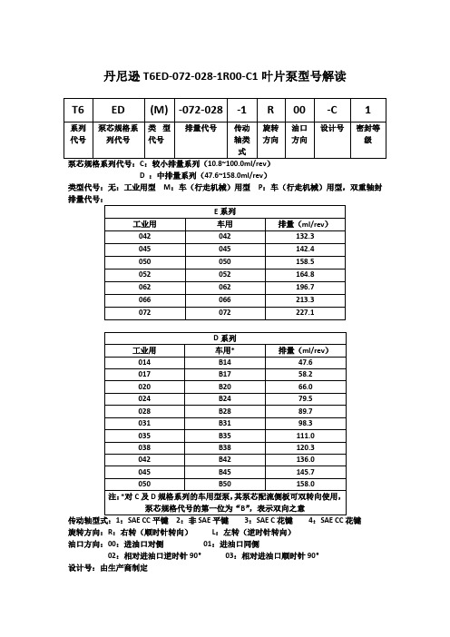
丹尼逊T6ED-072-028-1R00-C1叶片泵型号解读
泵芯规格系列代号:C:较小排量系列(10.8~100.0ml/rev)
D :中排量系列(47.6~158.0ml/rev)
类型代号:无:工业用型M:车(行走机械)用型P:车(行走机械)用型,双重轴封排量代号:
传动轴型式:1:SAE CC平键2:非SAE平键3:SAE C花键4:SAE CC花键
旋转方向:R:右转(顺时针转向)L:左转(逆时针转向)
油口方向:00:进油口对侧01:进油口同侧
02:相对进油口逆时针90°03:相对进油口顺时针90°
设计号:由生产商制定
密封等级:1=S1(适用于矿物油基液压油)常用的
4=S4(适用于抗燃液压液)
5=S5(矿物油基液压油及抗燃液压液,吸油口最高压力可达7bar)
以上是丹尼逊T6ED叶片泵的完整型号,再购买中能方便随时找到相应的型号,更多型号伊特液压随时欢迎咨询。
EATON 旋钮式手动控制阀门 E-VLSC-MC001-E 2009 12 版本说明书

EATON Screw-In Cartridge Valves E-VLSC-MC001-E December 2009 D-1.AAn Eaton BrandWhere measurements are critical request certified drawings. We reserve the right to change specifications without notice.Directional ControlsManual a nd p ilot o perated d irectional c ontrol v alves f or a pplicationsup to 350 bar (5000 psi) and 265 L/min (70 USgpm)EATON Screw-In Cartridge Valves E-VLSC-MC001-E December 2009D-2.A An Eaton BrandWhere measurements are critical request certified drawings. We reserve the right to change specifications without notice.Functional SymbolFlow Typical Model Cavity Rating PressurePageManual rotary valveL/min (USgpm) bar (psi)MRV3-10 C-10-3 23 (6) 210 (3000) D-100MRV13-10 C-10-3 23 (6) 350 (5000) D-110MRV13-12 C-12-3 46 (12) 350 (5000) D-120MRV3-16 C-16-3 64 (17) 210 (3000) D-130MRV13-16C-16-364 (17)350 (5000)D-140Flow Typical ModelCavityRatingPressurePageManual rotary valveL/min (USgpm) bar (psi)MRV4-10 C-10-4 11 (3) 210 (3000) D-150MRV14-10 C-10-4 11 (3) 350 (5000) D-160MRV14-12 C-12-4 23 (6) 350 (5000) D-170MRV4-16 C-16-4 45 (12) 210 (3000) D-180MRV14-16C-16-445 (12)350 (5000)D-190Flow Typical ModelCavityRatingPressurePageManual rotary valveL/min (USgpm) bar (psi)MRV5-10 C-10-4 11 (3) 210 (3000) D-200MRV15-10 C-10-4 11 (3) 350 (5000) D-210MRV15-12 C-12-4 23 (6) 350 (5000) D-220MRV5-16 C-16-4 45 (12) 210 (3000) D-230MRV15-16C-16-445 (12)350 (5000)D-240Flow Typical ModelCavityRatingPressurePageManual rotary valveL/min (USgpm) bar (psi)MRV6-10 C-10-4 11 (3) 210 (3000) D-250MRV6-16 C-16-4 11 (3) 300 (5000) D-256Flow Typical Model Cavity Rating PressurePageManual lever valve, spoolL/min (USgpm) bar (psi)MLV9-12-A C-12-460 (13.9)210 (3000)D-292Flow Typical ModelCavityRatingPressurePageManual lever valve, spoolL/min (USgpm) bar (psi)MLV9-12-BC-12-460 (15.9)210 (3000)D-293Flow Typical ModelCavityRatingPressurePageManual lever valve, spoolL/min (USgpm) bar (psi)MLV9-12-EC-12-460 (15.9)210 (3000)D-294Flow Typical ModelCavityRatingPressurePageManual lever valve, spoolL/min (USgpm) bar (psi)MLV9-12-F C-12-4 60 (15.9) 210 (3000) D-295EATON Screw-In Cartridge Valves E-VLSC-MC001-E December 2009 D-3.AAn Eaton BrandDWhere measurements are critical request certified drawings. We reserve the right to change specifications without notice.Functional SymbolFlow Typical Model Cavity Rating PressurePageCheck MO L/min (USgpm) bar (psi)3CP2A8795.5-15 (1.4-4)210 (3000)D-320Flow Typical ModelCavityRatingPressurePageManual pull valve, NC L/min (USgpm) bar (psi)MPV1-10 C-10-2 45 (12) 210 (3000) D-330MPV3-10C-10-245 (12)210 (3000)D-340Flow Typical ModelCavityRatingPressurePageManual push valve L/min (USgpm) bar (psi)MSV1-12 C-12-3 41.8 (11) 210 (3000) D-350MSV11-10 C-10-3 23 (6) 350 (5000) D-360MSV11-12 C-12-3 30 (8) 350 (5000) D-370MSV12-12C-12-338 (10)350 (5000)D-390Flow Typical ModelCavityRatingPressurePageManual push valve L/min (USgpm) bar (psi)MSV2-12C-12-338 (10)210 (3000)D-380Flow Typical ModelCavityRatingPressurePageManual push valve L/min (USgpm) bar (psi)MSV5-12 C-12-3 41.8 (11) 210 (3000) D-400MSV15-12C-12-341.8 (11)350 (5000)D-410Flow Typical ModelCavityRatingPressurePageManual push valve L/min (USgpm) bar (psi)MSV3-12 C-12-4 53.2 (14) 210 (3000) D-420MSV13-12C-12-4 53.2 (14) 350 (5000) D-430Flow Typical ModelCavity Rating PressurePageManual push valve L/min (USgpm) bar (psi)MSV4-12 C-12-4 53.2 (14) 210 (3000) D-440MSV14-12C-12-453.2 (14)350 (5000)D-450Flow Typical ModelCavityRatingPressurePageManual push valve L/min (USgpm) bar (psi)MSV6-12 C-12-4 53.2 (14) 210 (3000) D-460MSV16-12C-12-453.2 (14)350 (5000)D-470Flow Typical ModelCavityRatingPressurePageManual push valve L/min (USgpm) bar (psi)MSV17-10 C-12-4 20 (5.3) 350 (5000) D-480MSV7-12 C-12-4 45 (11.9) 210 (3000) D-490MSV17-12 C-12-4 20 (5) 350 (5000) D-5002EATON Screw-In Cartridge Valves E-VLSC-MC001-E December 2009D-4.A An Eaton BrandWhere measurements are critical request certified drawings. We reserve the right to change specifications without notice.Functional SymbolFlow Typical Model Cavity Rating PressurePagePilot to shift 2/2 valve L/min (USgpm) bar (psi)PTS7-10 C-10-3 30 (8) 210 (3000) D-510PTS17-10 C-10-3 30 (8) 350 (5000) D-520PTS17-12C-12-3114 (30)350 (5000)D-530Flow Typical ModelCavityRatingPressurePagePilot to shift 2/2 valve L/min (USgpm) bar (psi)1RDS702 A21145 80 (20) 420 (6090) D-560Flow Typical ModelCavityRatingPressurePageBrake sequence L/min (USgpm) bar (psi)1SB10 A893 10 (2.5) 350 (5000) D-540Flow Typical Model Cavity Rating PressurePageBrake release shuttle L/min (USgpm) bar (psi)1SB304 A5302 30 (8) 350 (5000) D-550Flow Typical Model Cavity Rating PressurePagePilot to shift valve L/min (USgpm) bar (psi)PTS1-10 C-10-4 30 (8) 210 (3000) D-570PTS11-12 C-12-4 76 (20) 350 (5000) D-580PTS11-10 C-10-4 30 (8) 350 (5000) D-590PTS1-16 C-16-4 132 (35) 210 (3000) D-600PTS11-16 C-16-4 132 (35) 350 (5000) D-610PTS1-20 C-20-4265 (70)210 (3000)D-620Flow Typical ModelCavityRatingPressurePagePilot to shift valve L/min (USgpm) bar (psi)PTS12-10 C-10-4 30 (8) 350 (5000) D-630PTS12-12 C-12-4 114 (30) 350 (5000) D-640PTS2-16 C-16-4 132 (35) 210 (3000) D-650PTS12-16 C-16-4 132 (35) 350 (5000) D-660PTS2-20 C-20-4 265 (70) 210 (3000) D-670EATON Screw-In Cartridge Valves E-VLSC-MC001-E December 2009 D-5.AAn Eaton BrandDWhere measurements are critical request certified drawings. We reserve the right to change specifications without notice.Functional SymbolFlow Typical Model Cavity Rating PressurePagePilot to shift valve L/min (USgpm) bar (psi)PTS13-10 C-10-4 30 (8) 350 (5000) D-680PTS13-12 C-12-4 113 (30) 350 (5000) D-690PTS3-16 C-16-4 132 (35) 210 (3000) D-700PTS13-16 C-16-4 132 (35) 350 (5000) D-710PTS3-20 C-20-4 265 (70) 210 (3000) D-720PTS6-16 C-16-4 132 (35) 210 (3000) D-790PTS16-16C-16-4132 (35)350 (5000)D-800Flow Typical ModelCavityRatingPressurePagePilot to shift valve L/min (USgpm) bar (psi)PTS14-12 C-12-4 114 (30) 350 (5000) D-730PTS14-16 C-16-4 132 (35) 350 (5000) D-740PTS5-16 C-16-4 132 (35) 210 (3000) D-770PTS15-16 C-16-4 132 (35) 350 (5000) D-780Flow Typical ModelCavity Rating PressurePagePilot to shift valve L/min (USgpm) bar (psi)PTS5-10 C-10-3 11 (3) 210 (3000) D-750PTS5-12C-12-3 105 (28) 350 (5000) D-760Flow Typical ModelCavity Rating PressurePagePilot to shift valve L/min (USgpm) bar (psi)PTS9-8 C-8-5S 19 (5) 280 (4000) D-810PTS9-10 C-10-5S 38 (10) 280 (4000) D-820PTS9-12 C-12-5S 76 (20) 280 (4000) D-830PTS9-16 C-16-5S 151 (40) 280 (4000) D-840PTS9-20C-20-5S 230 (60) 280 (4000) D-850Flow Typical Model Cavity Rating PressurePageHot oil shuttle L/min (USgpm) bar (psi)1HSH20 CVB-22-06-0 20 (5) 350 (5000) D-856EATON Screw-In Cartridge Valves E-VLSC-MC001-E December 2009D-6.A An Eaton BrandWhere measurements are critical request certified drawings. We reserve the right to change specifications without notice.This section gives the basic specifications for the complete line of Eaton's Integrated Hydraulics threaded cartridge non-solenoid directional control valves. Its purpose is to provide a quick, convenient reference tool when choosing Vickers cartridge valves or designing a system using these components.Two pressure ratings areshown for all products featured in this catalog – typical application pressure and fatigue pressure. The typical application pressure rating is the maximum recommended operating pressure for the valve in a given system. The fatigue pressure rating is the pressure for the valve to be free for infinite life from metal fatigue.Features and Benefits • P roducts in this catalog have been fatigue tested for one million cycles at 132% or 10 million cycles at 115% of rated pressure.• A ll operating parts arehardened steel, ground and honed for long life and low leakage.• D esigned for maximumflexibility and minimal space requirements.• A ll exposed cartridgesurfaces are zinc dichromate plated to resist corrosion.• A ll aluminum manifolds are gold anodized to resist corrosion.• D esired settings may be locked down.• A luminum knob and cap options are available on some models.• R eliable, economicaland compact.WARNINGFor pressure over 210 bar (3000 psi)use steel housing.Directional ControlsIntroductionFunctional SymbolFlow Typical Model Cavity Rating PressurePageSequence L/min (USgpm) bar (psi)DSV4-10 C-10-4 26 (6.9) 350 (5000) D-860DSV4-12C-12-4 113 (29.9) 350 (5000) D -866Flow Typical ModelCavityRatingPressurePageHot oil shuttle L/min (USgpm) bar (psi)1HSH701 A21145 80 (21) 420 (6000) D-870Flow Typical ModelCavity Rating PressurePagePilot to shift valve L/min (USgpm) bar (psi)PTS6-10 C-10-4 23 (6) 210 (3000) D-880PTS16-10 C-10-4 23 (6) 350 (5000) D-890PTS16-12C-12-4 76 (20) 350 (5000) D-900EATON Screw-In Cartridge Valves E-VLSC-MC001-E December 2009 D-7.AAn Eaton BrandDWhere measurements are critical request certified drawings. We reserve the right to change specifications without notice.90º90º50.8(2.00)50.8(2.00)88.95(3.502)65.9(2.595)50.69(1.996)67.82(2.670)22.23(0.875)Dowel Pin D2 and E2 Adjustment.20 in Mating Housing#29 (0.136 + 0.002) - 0.00045º90º321“D” Style367.82(2.670)50.64(1.994)46.21(1.819)90º50.8(2.00)(288.95(3.502)65.9(2.595)50.69(1.996)22.23(0.875)Dowel PinD2 and E2 Adjustment.20 in Mating Housing#29 (0.136+ 0.002) - 0.00045º90º321“D” Style 367.82(2.670)50.64(1.994)46.21(1.819)21“E2” StyleAlternative Adjusters For Light Duty Aluminum Housings Only 9,41,0(1.61)PortPort 1 to 258,0(2.28)Locating41,0(1.61)17,1 ±? 0.05(0.672 ± 0.002)Ø 3,45/3,50(#29 or 0.136)drill x 4,8(0.187) deepin mating housingThis hole omitted from detent plate of MRV3-10(V)-D2/E2Locating pin hole,four optional slots in detent plate RV3-*MRV3-*Locating Pin InstallationMRV3-**(V)-D(2)26,95 (1.061)(1.0.50) h ex25" -12 Th d.(0.43)11,0 (0.438)58,0(2.28)Port 3 to 1Port 1 to 2105 (4.13)Locating pin76,0(3.0)45°45°Mid position (not for 2-position models)7(25(224,9 ± 0.05(0.98 ± 0.002)Locating pin hole,four optional slots in detent plateØ 3,45 3,50(#29 or 0.136)drill x 4,8(0.187) deepin mating housingInstallation9,5 (0.37)41,0(1.61)Port 3 to 1Port 1 to 283,0(3.27)58,0(2.28)Locating pin45°45°M p (n 2m41,0(1.61)38,1(1.50)Ø 25,4 (1.0)42,0(1.65)50136)eephousingng pin hole,ptional slots ent plateMRV3-**(V)-D(2)MRV3-**(V)-E(2)ng Pin ation9,5 (0.37)(1.61)Port 1 to 283,0(3.27)58,0(2.28)Locating pin 45°Mid position (not for 2-position models)41,0(1.61)38,1(1.50)Ø 25,4 (1.0)42,0(1.65)17,1 ±? 0.05(0.672 ± 0.002)Ø 3,45/3,50(#29 or 0.136)drill x 4,8(0.187) deepin mating housingThis hole omitted from detent plate of MRV3-10(V)-D2/E2Locating pin hole,four optional slots in detent plateMRV3-**(V)-E(2)Locating PinInstallation D(2)Size 10Size 10E(2)Size 10Locating PIN Installation D(2)Size 12Size 12E(2)Size 12Locating PIN InstallationD(2)Size 16Size 16Locating PIN Installation 90º90º50.8(2.00)50.8(2.00)88.95(3.502)65.9(2.595)50.69(1.996)67.82(2.670)22.23(0.875)Dowel PinD2 and E2 Adjustment.20 in Mating Housing #29 (0.136 + 0.002) -0.00045º90º。
ATEX认证的低功耗小型液压阀门说明书

power ratings
hot/cold =
(W) 1/1,2
max. ambient temperature °C(2)
surface temperature
T6 85°C
T5 100°C
T4 135°C
40
55
60
ForversionswithLEDindicatorandelectricalprotection:
3xØ2 2 x Ø 3,5
9,7 == 15 ==
weight (1) 0,14
(1)withconnector.
Single subbase
Aluminiumorbrass
Adapter CNOMO size 30
(only for NC version) Aluminium
60 48
180°
function 2/2 way
NC 3/2 way
NC NO
MIX
connection
1
2
3
P
U
-
P
U
E
E
U
P
P2
U
P1
SEL
P:Pressure E:Exhaust
U2 P U1 U:Outlet
Subbasemountingsurface:ISO15218 (CNOMOE06.36.120N,size15)
ATEXU
31
2
(CFSCZN
prefix)
31
FEATURES • M ini-low consumption valves for use in potentially explosive atmospheres according to ATEX-Directive 2014/34/EU • EC type examination certificate (INERIS 10 ATEX 3016X) is in compliance with the European Standards EN 60079-0. EN 60079-15 and EN 60079-31 • Compact, monobloc solenoid pilot valve with spade-plug connector type DIN 43650, form C with 9,4 mm spacing • Version without integrated LED and electrical protection • Universal version for vacuum operation (3/2 way)
EX260-PEC1 产品名 一体化泵系统集成阀门 manifold 型号 EX260-PEC1说明

Doc. No.EX##-OMA1006SI Unit for ejector system integrated valve manifoldEX260-PEC1Safety InstructionsThese safety instructions are intended to prevent hazardous situations and/or equipment damage. These instructions indicate the level of potential hazard with the labels of "Caution", "Warning" or "Danger". They are all important notes for safety and must be followed in addition to International Standards (ISO/IEC)*1), and other safety regulations.*1) ISO 4414: Pneumatic fluid power -- General rules relating to systems.ISO 4413: Hydraulic fluid power -- General rules relating to systems.IEC 60204-1: Safety of machinery -- Electrical equipment of machines .(Part 1: General requirements)ISO 10218: Manipulating industrial robots -Safety.etc.Safety InstructionsRead and accept them before using the product.NOTE○Follow the instructions given below when designing, selecting and overseeing the product.•The instructions on design and selection (installation, wiring, environment, adjustment, operation,maintenance, etc.) described below must also be followed.*Product specifications•Use the specified voltage.Otherwise, failure or malfunction can result.•Reserve a space for maintenance.Allow sufficient space for maintenance when designing the system.•Do not remove any nameplates or labels.This can lead to incorrect maintenance, or misreading of the operation manual, which could cause damage or malfunction to the product.It may also result in non-conformity to safety standards.•Pay attention to the inrush current at power-up.Depending on the connected load, the initial charge current may cause the overcurrent protection and malfunction can result.•Product handling*Installation•Do not drop, hit or apply excessive shock to the fieldbus system.Otherwise, damage to the product can result, causing malfunction.•Tighten to the specified tightening torque.If the tightening torque is exceeded the mounting screws may be broken.IP67 protection cannot be guaranteed if the screws are not tightened to the specified torque.• When carrying the manifold, make sure that the connections are not stressed.Otherwise, the damage to connections can result. In addition, some combinations of the manifold may be very heavy, so use more than one person to carry or install the manifold.•Never mount a product in a location that will be used as a foothold.The product may be damaged if excessive force is applied by stepping or climbing onto it.*Wiring•Avoid repeatedly bending or stretching the cables or placing heavy load on them.Repetitive bending stress or tensile stress can cause breakage of the cable.•Wire correctly.Incorrect wiring can break the product.•Do not perform wiring while the power is on.Otherwise, damage to the fieldbus system and/or I/O device can result, causing malfunction.•Do not route wires and cables together with power or high voltage cables.Otherwise, the fieldbus system and/or I/O device can malfunction due to interference of noise and surge voltage from power and high voltage cables to the signal line.Route the wires (piping) of the fieldbus system and/or I/O device separately from power or high voltage cables.•Confirm proper insulation of wiring.Poor insulation (interference from another circuit, poor insulation between terminals, etc.) can lead to excess voltage or current being applied to the product, causing damage.•Take appropriate measures against noise, such as using a noise filter, when the fieldbus system is incorporated into equipment.Otherwise, noise can cause malfunction.*Environment•Select the proper type of protection according to the environment of operation.IP67 protection is achieved when the following conditions are met.However, when connected with JSY1000 manifolds, it is IP40.(1) The SI Unit is connected properly with fieldbus cable with M8 connector and power cable with M8 connector.(2) Suitable mounting of the SI Unit and manifold.(3) Be sure to fit a seal cap on any unused connectors.If using in an environment that is exposed to water splashes, please take measures such as using a cover.•Do not use in a place where the product could be splashed by oil or chemicals.If the product is to be used in an environment containing oils or chemicals such as coolant or cleaning solvent, even for a short time, it may be adversely affected (damage, malfunction etc.).•Do not use the product in an environment where corrosive gases or fluids could be splashed.Otherwise, damage to the product and malfunction can result.•Do not use in an area where surges are generated.If there is equipment that generates a large amount of surge (solenoid type lifter, high frequency induction furnace, motor, etc.) close to the fieldbus system, this may cause deterioration or breakage of the internal circuit of the fieldbus system. Avoid sources of surge generation and crossed lines.•When a surge-generating load such as a relay or solenoid is driven directly, use a fieldbus system with a built-in surge-absorbing element.Direct drive of a load generating surge voltage can damage the fieldbus system.•The product is CE marked, but not immune to lightning strikes. Take measures against lightning strikes in the system.•Prevent foreign matter such as remnant of wires from entering the fieldbus system to avoid failure and malfunction.•Mount the product in a place that is not exposed to vibration or impact.Otherwise, failure or malfunction can result.•Do not use the product in an environment that is exposed to temperature cycle.Heat cycles other than ordinary changes in temperature can adversely affect the inside of the product.•Do not expose the product to direct sunlight.If using in a location directly exposed to sunlight, shade the product from the sunlight.Otherwise, failure or malfunction can result.•Keep within the specified ambient temperature range.Otherwise, malfunction can result.•Do not operate close to a heat source, or in a location exposed to radiant heat.Otherwise, malfunction can result.*Adjustment and Operation•Perform settings suitable for the operating conditions.Incorrect setting can cause operation failure.•Please refer to the PLC manufacturer's manual etc. for details of programming and addresses. For the PLC protocol and programming refer to the relevant manufacturer's documentation.*Maintenance•Turn off the power supply, stop the supplied air, exhaust the residual pressure and verify the release of air before performing maintenance.There is a risk of unexpected malfunction.•Perform regular maintenance and inspections.There is a risk of unexpected malfunction.•After maintenance is complete, perform appropriate functional inspections.Stop operation if the equipment does not function properly.Otherwise, safety is not assured due to an unexpected malfunction or incorrect operation.•Do not use solvents such as benzene, thinner etc. to clean each unit.They could damage the surface of the body and erase the markings on the body.Use a soft cloth to remove stains.For heavy stains, use a cloth soaked with diluted neutral detergent and fully squeezed, then wipe up the stains again with a dry cloth.Fieldbus System/Industrial IoT Cybersecurity In recent years, factories have introduced industrial IoT, building up complex networks of production machines. These systems maybe subject to a new threat, cyberattack. To protect the industrial IoT from cyberattacks, it is important to take multiple measures (multi-layer protection) for IoT devices, networks and clouds.For this purpose, SMC recommends that the following measures are always taken into consideration. For further details of the following measures, please see security information published by your local country security agencies.1. Do not connect the devices via a public network.• If you unavoidably need to access the device orcloud via a public network, ensure to use a secure,private network such as VPN.• Do not connect an office IT network and factory IoT network.2. Build a firewall to prevent a threat from entering the device and system.• Set up a ro uter or firewall at network boundaries toallow minimum required communications.• Disconnect from the network or turn off the device if no continuous connection is required.3. Physically block an access to unused communication ports or disable them.• I nspect regularly each port if any unnecessarydevice is connected to the network system.• Operate necessary services (SSH, FTP, SFTP, etc.) only.• Set a transmission range of the device using awireless LAN or other radio system to the minimumrequired and use only devices approved according to the radio act in the country concerned.• Install a device generating radio waves in such place as there is no interference from indoor or outdoor. 4. Set up a secure communication method such as data encryption.• Encrypt data in every environment, including IoTnetworks, secure gate-way connections, for securecommunications.5. Grant access permissions by user accounts and limit the number of users.• Regularly review accounts and delete all unusedaccounts or permissions.• Establish an account lockout system to block anaccess to the account for a certain period if log-infails more than the given threshold.6. Protect passwords.• Change the default password when you firstuse the device or system.• Choose a long password (minimum 8characters) using a mix of different letters and characters to make the password more secure and harder to hack.7. Use the latest security software.• Install antivirus software on all computers todetect and remove viruses.• Keep the antivirus software up to date.8. Use the latest version of the device and system software.• Apply patches to keep the OS and applications up to date.9. Monitor and detect abnormalities in the network.• Keep monitoring t he network for anyabnormalities to take a prompt measure andissue an alert if any abnormality is detected.Install an intrusion detection system (IDS) and intrusion prevention system (IPS).10. Delete data from devices when disposed of. • Before disposi ng of any IoT devices, deletestored data or physically destruct media toprevent any misuse of the data.1.This document is an operation manual for a SI (Serial Interface) Unit which controls ejector system integrated valve manifold (JSY series). The SI Unit is a EtherCAT®-compatible device. EtherCAT® is registered trademark and patented technology, licensed by Beckhoff Automation GmbH, Germany. The SI Unit controls the manifold which has 5 pressure sensors max., and 24 valves output max.. For valve manifold, refer to the instruction manual for ejector system integrated valve manifold.Fig 1-1. The SI Unit structure2.Select the appropriate cables to mate with the connectors mounted on the SI Unit.2.1. Communication connectorECAT IN/OUT: M8 4 pin socket A-codedFig 2-1. Pin allocation of communication connectorWarningPay attention not to confuse the communication connector with the power connector. Incorrect connection may result in SI Unit failure. Check the printed character.2.2. Power connectorPWR IN: M8 4 pin plug A-codedPWR OUT: M8 4 pin socket A-codedFig 2-2. Pin allocation of power connectorPower-supply line for logic/sensors and power-supply line for valves are isolated. Be sure to supply power respectively.It can be used either with two different power supply or single-source power supply.NOTEThe recommended tightening torque is 0.2 Nm for both communication connectors and powerconnectors.2.3. FE terminalThe SI Unit must be connected to FE (Functional Earth) to divert electromagnetic interference. Connect a grounding cable from the FE terminal screw on the SI Unit to the nearest functional earth point. The grounding cable should be as thick and short as reasonably possible.The FE terminal and the metal parts of the communication/power connector are internally connected. The recommended tightening torque for FE terminal is 0.3 Nm.Fig 2-3. FE terminal3.1. ESI fileTo configure the SI Unit with your EtherCAT® master's software, the dedicated ESI (EtherCAT Slave Information) file is required. The ESI file contains all necessary information to configure the SI Unit on your master's software.The ESI file name is as follows. The ESI file can be downloaded from the SMC website.•ESI file: SMC_EX260-PECx_V10.xml3.2. Energy saving parameterNOTE•For energy saving function of ejector, see e.g. the catalogue for ejector system integrated valve manifold.The energy saving function is supported by ejector that can hold vacuum pressure.Check in advance whether your ejector is compatible with the energy saving function.•If there is an overlap OUT No. or order error in the set values, the Diagnosis history "Warning"occurs and SF LED flashes green and stops energy saving operation for sensor No. with error.•Incorrect OUT No. setting may result in unintended valve output.4.1. Input process data4.1.1. Pressure value of sensor No.x (of each 5 sensors)NOTE•Fixed at 0 for unconnected sensor.•Hold last data during happened sensor wire break and error etc..4.1.2. Valve-coil(s) short circuit diagnosis4.1.3. Unit diagnosis4.1.4. Sensor state of sensor No.x (of each 5 sensors)NOTEFor judgement of vacuum/pressure generation, refer to Section 5.1.1 and Section 6.4.2. Output process data4.2.1. Output5.NOTE*1) RO means Read only, WO means Write only, and RW means both Read and Write are allowed. Those with a trailing P are the Index assigned to the process data, and the format is the same.5.1. Sensor parameters(Index 0x8009/8019/8029/8039/8049)5.1.1. Pressure parameter (Subindex 0x01...0x08)NOTE•If the pressure parameter set values do not fulfil the conditions in (1)...(4) above, the Diagnosis history "Warning" occurs and SF LED flashes green and applicablevacuum/pressure state bit (Offset 0.0...0.3 in Section 4.1.4) is fixed at 0 for the applicable sensor.•If the pressure parameter set values do not fulfil the conditions in (2) above and the energy saving parameter is set to other than Disable, stop energy saving operation for the applicable sensor.5.1.2. Supply valve type (Subindex 0x09)NOTE•The setting must match supply valve type of actual ejector. If the settings are different from the actual specifications, energy saving operation is not possible.5.1.3. Valve protection (Subindex 0x0A)5.2. Output parameters5.2.1. Output counter (Index 0xF120)5.2.2. Output operation at network fault (Index 0xF800)5.2.3. Output counter limit monitoring(Index 0xF801)5.2.4. Output counter limit value (Index 0xF802)5.3. General parameters5.3.1. Number of sensors (Index 0xF803)NOTE•If the number of sensors detected by the SI Unit is greater than the set number, the unit will operate normally without occurring an error.5.4. Command parameters5.4.1. Zero offset (Index 0xB008/B018/B028/B038/B048/FB00)NOTE•Zero offset should be performed with sensor open to the atmosphere.Zero offset is performed only when the pressure value is within ±2 % F.S. of atmospheric pressure.•"Zero offset reset request" clears the zero offset correction.•"Zero offset of all sensors" is used to zero offset all sensors at once.5.4.2. Valve protection release (Index 0xFB01)NOTE•Valve protection release is performed for all ejectors at once.•If the valve protection occurs, the diagnostic bit will be deleted, and the SF LED will be turned off by the above requests.5.4.3. Output count reset (Index 0xFB02)NOTE•The Output count reset can be reset for each output individually and is entered according toa 4 byte (32 bit) number.Example: Set 0x00001234 -> Output count reset request of OUT2,4,5,9,12Example: Set 0x1234ABCD -> Output count reset request of OUT0,2,3,6,7,8,9,11,13,15,18,21•If output count over occurs, the diagnostic bit will be deleted, and the SF LED will be turned off by the above requests.6.Fig 6-1. Example of energy saving operation (Conditions under which release pressure is generated) • (1)When the vacuum instruction is ON, the supply valve is automatically closed when the vacuum pressure reaches P2.• (2)When the vacuum pressure drops by P2-H2, the supply valve is automatically opened again. • (3)Repeat steps (1) and (2) unless the valve protection is activated.• (4)The vacuum P1 state bit is set to 1 until the vacuum pressure reaches P1 and then drops to P1-H1. • (5)The vacuum P2 state bit is set to 1 until the release pressure reaches P2 and then drops to P2-H2. • (6)The pressure P3 state bit is set to 1 until the vacuum pressure reaches P3 and then drops to P3-H3. • (7)The pressure P4 state bit is set to 1 until the vacuum pressure reaches P4 and then drops to P4-H4. • The above pressure threshold/hysteresis combinations are set by CoE services, Refer to Section 5.1.1.Vacuum instruction (OUTx ON/OFF)Supply valve Release instruction (OUTy ON/OFF)Vacuum P2state bit Release Valve Vacuum P1state bit Pressure P3state bit Pressure P4state bitEnergy saving parameter set to OUTx-y, Supply valve type : N.C.Threshold of Vacuum P1Energy savingoperationThreshold of Pressure P3Threshold of Pressure P47.7.1. LED IndicationFig 7-1. LED Indicators of the SI UnitRUN ERR SF L/A1L/A2PWR PWR(V)Fig 7-2. LED lighting patterns 7.2. Diagnosis history8.8.1. DimensionsFig 8-1. Dimensions of the SI Unit8.2. SpecificationsNOTE*1: SI Unit power supply voltage specification. Supply power according to the solenoid valve used.9.(1) Seal capPart number: EX9-AWESThis cap is used to protect the M8 socket connector opening when the connector is not used.When a connector is not used, the seal cap can keep the SI Unit under IP67 rated protection.(2 pcs. are included with the SI Unit as an accessory.)Fig 9-1. EX9-AWES10.The state of the SI Unit is indicated by the LED indication.If a problem occurs on the SI Unit, you can use the following chart to troubleshoot.Also refer to the online diagnostics via the EtherCAT® master software to help identify the problem.10.1. Troubleshooting chartFig 10-1. Troubleshooting chart10.2. Troubleshooting tablesNOTE•The Diagnosis history (Section 7.2) allows identification of the OUT No. or sensor No. that is causing the problem.4-14-1, Sotokanda, Chiyoda-ku, Tokyo 101-0021 JAPANTel: + 81 3 5207 8249 Fax: +81 3 5298 5362URL https://Note: Specifications are subject to change without prior notice and any obligation on the part of the manufacturer.© 2022 SMC Corporation All Rights ReservedNo.EX##-OMA1006。
叶片式液压泵 T7CS 系列产品介绍说明书

T7CS, Denison 叶片泵主要技术信息泵理论排量Vi最高转速最高压力HF-0, HF-1HF-2HF-4, HF-5HF-0, HF-2HF-1, HF-4, HF-5系列规格间歇连续间歇连续cm 3/rev.rpmrpmbarbarbarbarT7C SE1758,325001800260230210175E2063,8E2270,3E2579,31500HF-0, HF-2 = 石油基抗磨液压油 HF-1 = 石油基液压油(非抗磨)HF-4 = 水乙二醇液HF-5 = 合成液压油(磷酸脂液等)注:更多的详细资料,或若上列性能参数不能满足您的特殊工况要求,请与当地的派克办事处联系。
主要特征性能稳定T7CS 系列叶片泵是为变速驱动而设计的,并且转速范围很宽。
和我们其他的T7系列叶片泵一样,随着时间的推移,性能仍然很稳定,使得该类叶片泵成为现代电液操作机器的理想解决方案。
寿命长压力平衡概念增加了泵的寿命。
而双唇口叶片增加了抗固体颗粒污染能力。
噪音低Denison 叶片泵技术在泵的整个工作范围和整个生命周期中允许低的噪音水平。
通用性和紧凑性T7CS 系列叶片泵提供了几种排量规格,最大达80 cc/rev,在不改变泵与电机连接的前提下,很好地扩展了T7BS 系列叶片泵的排量规格。
T7CS 系列叶片泵也可以选用SAE 花键轴,允许泵轴直接与电机轴相连接。
T7CS, Denison 叶片泵订货代号及安装尺寸型号T7CS - E25 - 4 R 00 - A 1 MW - MØ48SUCTION Ø25,4PRESSURE PST7CS 系列 - SAE J744SAE B 2孔安装法兰排量容积排量(cm3/rev.)E17 = 58,3E20 = 63,8E22 = 70,3E25 = 79,3传动轴类型1 = 平键轴(SAE B)3 = 花键轴(SAE B) 13齿4 = 花键轴(SAE BB) 15齿转向(从轴端方向看)R = 右转(顺时针)L = 左转(逆时针)修改代码Ex : NOP = 不喷漆油口形式MW = S = 特殊的法兰P = 1" - SAE J518 4螺栓法兰 公制螺纹密封等级1 = S1 BUNA N 5 = S5 VITON®设计序列号油口方向配置00 = 标准配置输入扭矩极限:轴Vi [cm 3/rev] x p max. [bar]Nm 116500262320600327420600327重量:23,0 kg转动惯量:7,5 Kgm 2 x 10⁻⁴P = 压油口S = 吸油口派克汉尼汾在中国的联系方式派克汉尼汾中国总部上海市金桥出口加工区云桥路280号邮编:201206电话:+86 - 21 - 2899 5000北京分公司北京经济技术开发区荣华南路2号院2号楼2201室邮编:100004电话:+86 - 10 - 8527 7300广州分公司广州市萝岗区科学城彩频路11号广东软件科学园F栋202室邮编:510663电话:+86 - 20 - 3212 1688大连办事处大连市高新园区火炬路3号纳米大厦11层1101室邮编:116023电话:+86 - 411 - 3964 6767西安办事处西安市高新区定昆池三路777号邮编:710065电话:+86 - 29 - 8111 8062成都办事处成都市锦江区锦东路568号摩根中心2栋10楼7号邮编:610066电话:+86 - 28 - 6180 6800长沙服务中心长沙市经济技术开发区板仓南路26号新长海数码中心2楼V24-V25室邮编:410005电话:+86 - 731 - 8985 1529派克汉尼汾香港有限公司香港九龙尖沙咀海港城港威大厦2座20楼01 - 04室电话:+86 - 852 - 2428 800819-06-B HYD-CH-4P-T7CSVSD。
Eaton Moeller 系列 Rapid Link 速控器 198868 说明书
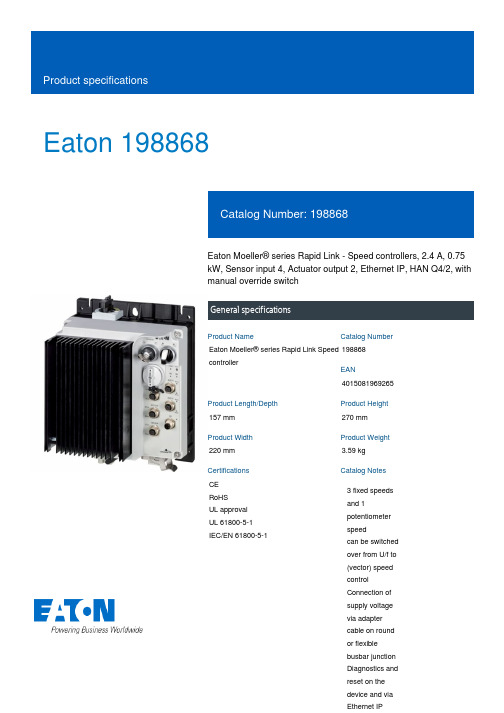
Eaton 198868Eaton Moeller® series Rapid Link - Speed controllers, 2.4 A, 0.75 kW, Sensor input 4, Actuator output 2, Ethernet IP, HAN Q4/2, with manual override switchGeneral specificationsEaton Moeller® series Rapid Link Speed controller1988684015081969265157 mm 270 mm 220 mm 3.59 kg CE RoHS UL approval UL 61800-5-1 IEC/EN 61800-5-1Product NameCatalog NumberEANProduct Length/Depth Product Height Product Width Product Weight Certifications Catalog Notes 3 fixed speeds and 1 potentiometer speedcan be switched over from U/f to (vector) speed control Connection of supply voltage via adapter cable on round or flexible busbar junction Diagnostics and reset on the device and via Ethernet IPParameterization: drivesConnect mobile (App) Parameterization: drivesConnectParameterization: FieldbusParameterization: KeypadIGBT inverterPTC thermistor monitoringSelector switch (Positions: REV - OFF - FWD)Key switch position OFF/RESETKey switch position HANDTwo sensor inputs through M12 sockets (max. 150 mA) for quick stop and interlocked manual operationThermo-click with safe isolationKey switch position AUTO2 Actuator outputsControl unitInternal DC linkPC connectionManual override switch3 fixed speeds1 potentiometer speed IP65NEMA 121st and 2nd environments (according to EN 61800-3)IIISpeed controllerEtherNet/IPC2, C3: depending on the motor cable length, the connected load, and ambient conditions. External radio interference suppression filters (optional) may be necessary.C1: for conducted emissions only2000 VAC voltagePhase-earthed AC supply systems are not permitted. Center-point earthed star network (TN-S network)Vertical15 g, Mechanical, According to IEC/EN 60068-2-27, 11 ms, Half-sinusoidal shock 11 ms, 1000 shocks per shaftResistance: 57 Hz, Amplitude transition frequency on accelerationResistance: According to IEC/EN 60068-2-6Resistance: 10 - 150 Hz, Oscillation frequencyResistance: 6 Hz, Amplitude 0.15 mm Above 1000 m with 1 % performance reduction per 100 m Max. 2000 m-10 °C40 °C-40 °C70 °CFeatures Fitted with:Functions Degree of protectionElectromagnetic compatibility Overvoltage categoryProduct categoryProtocolRadio interference classRated impulse withstand voltage (Uimp) System configuration typeMounting position Shock resistance Vibration AltitudeAmbient operating temperature - min Ambient operating temperature - max Ambient storage temperature - min Ambient storage temperature - max Climatic proofingIn accordance with IEC/EN 50178< 95 %, no condensationCurrent limitationAdjustable, motor, main circuit0.2 - 2.4 A, motor, main circuitDelay time< 10 ms, Off-delay< 10 ms, On-delayEfficiency97 % (η)Input current ILN at 150% overload2.5 ALeakage current at ground IPE - max3.5 mAMains current distortion120 %Mains switch-on frequencyMaximum of one time every 60 secondsMains voltage - min380 VMains voltage - max480 VMains voltage tolerance380 - 480 V (-10 %/+10 %, at 50/60 Hz)Operating modePM and LSPM motorsBLDC motorsSynchronous reluctance motorsU/f controlSensorless vector control (SLV)Output frequency - min0 HzOutput frequency - max500 HzOverload currentAt 40 °CFor 60 s every 600 sOverload current IL at 150% overload3.6 A45 Hz66 Hz0.75 kW400 V AC, 3-phase480 V AC, 3-phase0.1 Hz (Frequency resolution, setpoint value)200 %, IH, max. starting current (High Overload), For 2 seconds every 20 seconds, Power section50/60 Hz8 kHz, 4 - 32 kHz adjustable, fPWM, Power section, Main circuitAC voltagePhase-earthed AC supply systems are not permitted.Center-point earthed star network (TN-S network)1 HP≤ 0.6 A (max. 6 A for 120 ms), Actuator for external motor brakeAdjustable to 100 % (I/Ie), DC - Main circuit10 kAType 1 coordination via the power bus' feeder unit, Main circuit 24 V DC (-15 %/+20 %, external via AS-Interface® plug)Ethernet IP, built inPlug type: HAN Q4/2Specification: S-7.4 (AS-Interface®)Max. total power consumption from AS-Interface® power supply unit (30 V): 250 mANumber of slave addresses: 31 (AS-Interface®)C2 ≤ 5 m, maximum motor cable length C3 ≤ 25 m, maximum motor cable length C1 ≤ 1 m, maximum motor cable lengthMeets the product standard's requirements.Meets the product standard's requirements.Rated frequency - minRated frequency - maxRated operational power at 380/400 V, 50 Hz, 3-phase Rated operational voltageResolutionStarting current - maxSupply frequencySwitching frequencySystem configuration type Assigned motor power at 460/480 V, 60 Hz, 3-phase Braking currentBraking torqueRated conditional short-circuit current (Iq)Short-circuit protection (external output circuits) Rated control voltage (Uc)Communication interfaceConnectionInterfacesCable length10.2.2 Corrosion resistance10.2.3.1 Verification of thermal stability of enclosures10.2.3.2 Verification of resistance of insulating materials tonormal heatMeets the product standard's requirements.Meets the product standard's requirements.Meets the product standard's requirements.Does not apply, since the entire switchgear needs to be evaluated.Does not apply, since the entire switchgear needs to be evaluated.Meets the product standard's requirements.Does not apply, since the entire switchgear needs to be evaluated.Meets the product standard's requirements.Does not apply, since the entire switchgear needs to be evaluated.Does not apply, since the entire switchgear needs to be evaluated.Is the panel builder's responsibility.Is the panel builder's responsibility.Is the panel builder's responsibility.Is the panel builder's responsibility.Is the panel builder's responsibility.The panel builder is responsible for the temperature rise calculation. Eaton will provide heat dissipation data for the devices.Generation change from RA-SP to RASP 4.0Connecting drives to generator suppliesGeneration change RAMO4 to RAMO5Generation change from RA-MO to RAMO 4.0Generation Change RASP4 to RASP5Electromagnetic compatibility (EMC)Configuration to Rockwell PLC for Rapid LinkGeneration Change RA-SP to RASP5Rapid Link 5 - brochureDA-SW-drivesConnect - InstallationshilfeDA-SW-Driver DX-CBL-PC-3M0DA-SW-USB Driver PC Cable DX-CBL-PC-1M5DA-SW-drivesConnect - installation helpDA-SW-drivesConnect USB Driver DX-COM-PCKITDA-SW-USB Driver DX-COM-STICK3-KITDA-SW-drivesConnectMaterial handling applications - airports, warehouses and intra-logisticsProduct Range Catalog Drives EngineeringProduct Range Catalog Drives Engineering-ENDA-DC-00004184.pdfDA-DC-00004514.pdfDA-DC-00003964.pdfDA-DC-00004508.pdfeaton-bus-adapter-rapidlink-speed-controller-dimensions-005.eps eaton-bus-adapter-rapidlink-speed-controller-dimensions-004.eps eaton-bus-adapter-rapidlink-speed-controller-dimensions-003.eps eaton-bus-adapter-rapidlink-speed-controller-dimensions-002.epsETN.RASP5-2420EIP-412R000S1.edzIL034093ZU10.2.3.3 Resist. of insul. mat. to abnormal heat/fire by internalelect. effects10.2.4 Resistance to ultra-violet (UV) radiation10.2.5 Lifting10.2.6 Mechanical impact10.2.7 Inscriptions10.3 Degree of protection of assemblies10.4 Clearances and creepage distances10.5 Protection against electric shock10.6 Incorporation of switching devices and components 10.7 Internal electrical circuits and connections10.8 Connections for external conductors10.9.2 Power-frequency electric strength10.9.3 Impulse withstand voltage10.9.4 Testing of enclosures made of insulating material 10.10 Temperature rise Application notes BrochuresCatalogues Certification reports DrawingseCAD model Installation instructionsEaton Corporation plc Eaton House30 Pembroke Road Dublin 4, Ireland © 2023 Eaton. All rights reserved. Eaton is a registered trademark.All other trademarks areproperty of their respectiveowners./socialmediaIs the panel builder's responsibility. The specifications for the switchgear must be observed.Is the panel builder's responsibility. The specifications for the switchgear must be observed.The device meets the requirements, provided the information in the instruction leaflet (IL) is observed.Rapid Link 5MN034004ENMZ040046_ENMN040003_ENDA-MN-MZ040044ENrasp5_v31.stpramo5_v31.dwg10.11 Short-circuit rating10.12 Electromagnetic compatibility 10.13 Mechanical function Installation videos Manuals and user guidesmCAD model。
T6 叶片泵进出油口连接螺纹系列号说明
T6 单泵型号 T6C — 010 — 1 R 00 — B 1 M0
油口连接螺纹
油 口 法 兰 规 格 S T6C T6D T6E 1 1/2″ 2″ 3″ P 1″ 1 1/4″ 1 1/2″
油口螺纹 公制螺纹 M0 M0 M0 UNC螺纹 00 00 00
可省略 可省略 可省略
T6双联泵型号 双联泵型号
T6CC — 025 — 020 — 1 R 00 — C 1 M0
油口连接螺纹
油 口 法 兰 规 格 S 3″ T6CC 2 1/2″ 3″ 2 1/2″ T6DC T6EC T6ED 3″ 3 1/2″ 4″ 11/4″ 1 1/2″ 1 1/2″ 1″
3/4″
油口螺纹 P2 1″ 1″
3/4″
P1 1″
公制螺纹 M00 M10 M01 M11 M0 M0 M0UNC螺纹 0ຫໍສະໝຸດ 10 01 11 00 00 00
可省略 可省略 可省略
1″ 1″ 11/4″
注:1)油口连接螺纹系列号编制参照T7泵。
2)油口公制连接螺纹的尺寸: T6C 同 T7B; T6D 同 T7D; T6E 同 T7E; T6DC 同 T67DC; T6EC 同 T67EC; T6ED 同 T7ED。 3)T6CC 油口公制连接螺纹的间距尺寸同 UNC 油口。 公制螺纹的直径为: 3/4″——M10×19; 1″——M10×19; 2 1/2″——M12×22; 3″——M16×28。 4)T6泵进出油口公制连接螺纹的尺寸可详见附表。
T6CC-031-010-1R00-C1叶片泵型号解读
丹尼逊T6CC-031-010-1R00-C1叶片泵型号解读
泵芯规格系列代号:C:较小排量系列(10.8~100.0ml/rev)
类型代号:无:工业用型M:车(行走机械)用型P:车(行走机械)用型,双重轴封辅助类型代号:采用重载传动轴,仅适用于T6CC,T6CC*,T6DC及T6DC*
传动轴型式:1:非SAE平键3:SAE BB花键5:SAE B平键
旋转方向:R:右转(顺时针转向)L:左转(逆时针转向)
油口方向:00:进油口对侧01:进油口同侧
02:相对进油口逆时针90°03:相对进油口顺时针90°
设计号:由生产商制定
密封等级:1=S1(适用于矿物油基液压油)常用的
4=S4(适用于抗燃液压液)
5=S5(矿物油基液压油及抗燃液压液,吸油口最高压力可达7bar)
以上是丹尼逊T6CC叶片泵的完整型号,再购买中能方便随时找到相应的型号,如遇到特殊型号的,伊特液压随时欢迎咨询。
丹尼逊T6C-031-1R00-B1叶片泵型号解读
丹尼逊T6C-031-1R00-B1叶片泵型号解读
泵芯配流侧板类型:-0:单转向型-B:双转向型(仅使用于C/D系列车用性泵)
排量代号:
传动轴型式:1:SAE B平键2:非SAE B平键3:SAE B花键4:SAE BB花键
旋转方向:R:右转(顺时针转向)L:左转(逆时针转向)
油口方向:00:进油口对侧01:进油口同侧
02:相对进油口逆时针90°03:相对进油口顺时针90°
设计号:由生产商制定
密封等级:1=S1(适用于矿物油基液压油)常用的
4=S4(适用于抗燃液压液)
5=S5(矿物油基液压油及抗燃液压液,吸油口最高压力可达7bar)
以上是丹尼逊T6C叶片泵的完整型号,再购买中能方便随时找到相应的型号,如遇到特殊型号的,伊特液压随时欢迎咨询(微信:itty6868)。
丹尼逊液压泵叶片泵Denison vane pumps
T6E – 流量 42 to 85 GPM;(132.3 — 269ml/rev)
042 045 050 052 062 066 072 085
新 T7B – 流量 2 to 15 GPM。(5.8 — 50ml/rev)
002 003 004 006 008 011 012 013 015
额定流量按 1200 RPM 可有行走机械(车用)标准产品
7
叶片泵产品
不同的定子尺寸
定子圈外径
T6C-010 内部尺寸
T6C-028 内部尺寸
16
叶片泵产品
T6 叶片泵工作原理示图
17
叶片泵产品
T6 叶片泵工作原理剖视图
18
叶片泵产品
Denison 叶片泵特征
液压平衡转子 吸口
无侧向液压负载
IN
OUT
出口 齿轮泵: 无平衡功能,出口高 压力会造成较大的侧向负载力
19
叶片泵产品
Denison 叶片泵特征
整体式泵芯概念
所有泵唧零件均组合在一个泵芯组件内
20Biblioteka 叶片泵产品柱销式叶片顶销
较小的叶片撞击
高压油
21
叶片泵产品
柱销叶片设计优点
2002/6/30
叶片泵产品
传动轴扭矩限制
举例:对T6DC-050-014 泵,如何确定其在最高 间断压力下传动轴所需的扭矩?
泵排量: 050 = 9.64 in3/rev. : 014 = 2.81 in3/rev.
最高间断压力:3000 psi :
4000 psi
050所需扭矩:9.64 x 3000 = 28920
- 1、下载文档前请自行甄别文档内容的完整性,平台不提供额外的编辑、内容补充、找答案等附加服务。
- 2、"仅部分预览"的文档,不可在线预览部分如存在完整性等问题,可反馈申请退款(可完整预览的文档不适用该条件!)。
- 3、如文档侵犯您的权益,请联系客服反馈,我们会尽快为您处理(人工客服工作时间:9:00-18:30)。
丹尼逊T6EDC-042-028-003-1R00-C1叶片泵型号解读
规格系列代号:C:较小排量系列(10.8~100.0ml/rev)
D:中排量系列(47.6~158.0ml/rev)
E:大排量系列(132.3~227.1ml/rev)
可提供三联规格组合有:DCC,DDCS和EDC
类型代号:无:工业用型
M:车(行走机械)用型
S:车(行走机械)用型,采用SAE J744C安装法兰,仅用于T6DDS及T6EDCS
传动轴形式:
T6EDCM:-1:ISO G45N平键-3:SAE D/E花键
T6EDCS:-2:SAE D/E平键-3:SAE D/E花键
旋转方向:R:右转(顺时针转向)L:左转(逆时针方向)
油口方向:00为标准的油口方向配置
密封等级:1:S1(使用与矿物油基液压油)
4:S4(使用于抗燃液压液)
5:S5(矿物油基液压油及抗燃液压液,吸口最高压力可达7bar)
以上是丹尼逊T6EDC三联叶片泵的完整型号,购买时能方便随时找到相应的型号,更多型号伊特液压随时欢迎咨询。