楚鹰科技张力控制器ST6400说明书
张力控制器说明书TC-608P

迴授式張力控制器盤面型TC-608P(內建LOAD CELL 放大檢出)(具通訊功能)使用操作說明書1.前言非常感謝您採用本公司開發TC-608P迴授式張力控制器(以下簡稱608P)。
在使用608P之前,為了充分地發揮608P的功能,以及確保使用者的安全,請先閱讀本說明書,以利方便日後的配線設計,參數設定及了解異常現象發生的原因與處理方法,請妥善保管本說明書。
當您使用中出現任何疑點本手冊無法提供您解決方案時,請您與本公司連絡,我們將竭誠為您服務,並請您繼續採用本公司的產品以及批評指教。
2.注意事項:.不可在送電中實施配線、或拆裝608P控制器的連接器。
.608P控制器的端子均為控制器的迴授信號與輸出信號接點,請勿作為他用。
.608P控制器的輸出端絕對不可連接至AC電源,及異電壓進入。
.請勿拆卸控制器外殼及做控制器零件的耐壓測試。
.電源是否為AC 220V ±10%輸入608P端子1,2接點。
3.TC-608P原理介紹本控制器是依據生產線上使用條件之設定捲取或放料以及物料生產所需的張力值,TC-608P會依設定以及LOAD CELL所傳回的感測值作比較計算後,修正輸出指令,以改變剎車力或捲取扭力的大小,自動達成實際張力和設定需求張力相同的高精度張力控制系統。
4.特點介紹:.高精度,高可靠性。
.張力值可以自行定義為:kg / N / LB。
.可直接接LOAD CELL輸入,數位化歸零與倍率調整功能設計,方便操作。
.數位化設計,特性不變。
.具人性化設計,易操作。
.具張力設定值、張力實際值輸出指令多功能顯示。
.具有主速加、減速增益延遲時間輸出功能。
.具參數停電記憶功能。
.具啟動增益功能,可補償啟動機械靜摩擦力。
.具停機張力打折功能,可克服停機張力過大問題。
.具RS-485通訊介面,可與PLC以及PC通訊。
.■ 標準規格外殼尺寸 : 96mm X 96 mm 開孔尺寸 : 92 mm X 92 mm電 源 電 壓AC 220 V + 10%硬 體 規 格1 組 LOAD CELL 輸入 0 ~ 4 mV 輸入, 浮動式歸零與放大2組AI (選配) DC 0~10V 輸入,12 bit 解析度,輸入阻抗200K 1組AO (1組選配) DC 0~10V 輸出,最大10mA ,12 bit 解析度 4組DI 乾接點或晶體方式(Low Active) 2組RELAY DO Relay A 接點 5A 250VAC/30VDCRS-485 MODBUS 通訊 (選配) 通訊採用RS-485介面 MODBUS RTU 協定,可由通訊啟動、修正、指定輸出、讀取等操作。
6400基本使用方法

(3)操作面板
操作面板总共有 64 键,中间是显示屏,显示屏左右两侧对称有分别有 4 个方向键、Pgdw、 Pgup、Home、End 等键,主要是用来移动光标。左右对称的还有 2 个 enter 键。左右键的功 能都是一样的,为了方便做实验时左右手的操作进行的设计。
显示屏下面有 5 个红色 f1、f2、f3、f4、f5 键,我们称之为功能键(function)。功能键在 不同的界面,对应显示屏上相应的菜单,功能键在以后的操作中将发挥重要的作用。
2、菜单介绍
欢 Welcome 迎 Menu 菜
单 Config 配 Menu 置
菜 单
Calib
调
Menu 零
菜
单
New
测
Msmnts 量 菜
单
Utility 应 Menu 用
菜
单
About this unit 系统信息,如版本、编号等;
Diagnostics & test 测试和机器诊断
Quit open –IRGA on 退出 open 操作系统,让 IRGA 开 Quit open- IRGA off 退出 open 操作系统,让 IRGA 关,关机的意思
A:净光合速率,assimilation rate 与 Pn一样,单位是μmol CO2 m-2s-1。 Cr:参比室(reference)CO2浓度,单位是μmol CO2 mol-1 air。 Cs:样品室(sample)CO2浓度,单位是μmol CO2 mol-1 air。 F: 流速,(flow rate),单位是μmols-1。 S: 叶片面积,单位是cm2。 Wr:参比室(reference)H2O浓度,单位是mmol H2O mol-1 air。 Ws:样品室(sample)H2O浓度,单位是mmol H2O mol-1 air。
智能控制器使用手册
一概述智能控制器是框架式空气断路器的核心部件,适用于50~60Hz电网,主要用作配电、馈电或发电保护,使线路和电源设备免受过载、短路、接地/漏电、电流不平衡、过压、欠压、电压不平衡、过频、欠频、逆功率等故障的危害;通过负载监控,需量保护,区域连锁等功能实现电网的合理运行.同时也用作电网节点的电流、电压、功率、频率、电能、需量、谐波等电网参量的测量;故障、报警、操作、电流历史最大值、开关触头磨损情况等运行维护参数的记录;当电力网络进行通讯组网时,智能控制器可用为电力自动化网络的远程终端实现遥测,遥信,遥控,遥调等,智能控制器支持多种协议以适用不同的组网要求。
二基本功能对于M型无任何可选功能(加*的项目)时其功能配置为基本功能,如表1所示:表1 基本功能配置2。
1.3 通讯功能通讯功能为可选项,对于M型没有通讯功能,对于H型通讯协议可根据需要选择为Modbus,Profibus-DP,Device net。
2。
1.4增选功能选择增选功能为可选项,M型,H型都可以选择增选功能配置,不同增选功能代号与增选功能内容如表2所示.表2 增选功能配置表2。
1。
5 区域连锁及信号单元的选择“区域连锁及信号单元”为可选项,M型、H型都可以选择信号单元的功能配置,当信号单元选择为S2,S3时,控制器具备区域连锁功能.2.2 技术性能2。
2.1 适用环境工作温度:-10℃~+70℃(24h•内平均值不超过+35℃)储存温度:-25℃~+85℃安装地点最湿月的月平均最大相对湿度不超过90%,同时该月的月平均最低温度不超过+25℃,允许由于温度变化产生在产品表面的凝露.污染等级:3级。
(在和断路器装配在一起的情况下)安装类别:Ⅲ。
(在和断路器装配在一起的情况下)2.2.2工作电源由辅助电源和电源互感器同时供电,保证负载很小和短路情况下控制都可以可靠工作。
控制器的供电方式有下面3种方式:a。
电源CT供电额定电流大于等于400A时,一次电流单相不低于0.4In,三相不低于0。
楚鹰ST全自动张力控制器
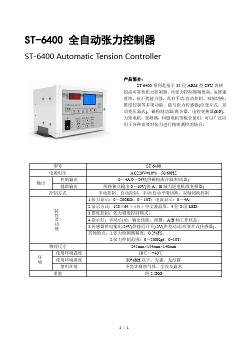
ST-6400 全自动张力控制器
ST-6400 Automatic Tension Controller
产品简介:
ST-6400系列是基于32位ARM型CPU内核
的高可靠性张力控制器。
该张力控制器精度高,运算速
度快,抗干扰能力强,具有手动/自动控制、双轴切换、
锥度控制等多项功能,能与张力传感器(应变片式、差
动变压器式),磁粉制动器/离合器,电控变换器(E/P),
力矩电机,变频器,伺服电机等配合使用,可以广泛应
用于各种需要对张力进行精密测控的场合。
型号ST-6400
电源电压AC220V±10% 50/60HZ
输出
控制输出0~4A/0~24V(供磁粉离合器/制动器)
辅助输出两路独立输出0~10V(供A、B轴力矩电机或变频器)
控制方式手动控制、自动控制,手动/自动平滑切换,双轴切换控制特
性
及
功
能
1.张力显示:0~200KG、0~10T;电流显示:0~4A;
2.显示方式:128×64(点阵)中文液晶屏、4位8段LED;
3.锥度控制:张力锥度控制模式;
4.指示灯:手动/自动,输出使能,报警,A/B轴工作状态;
5.传感器供电输出:24V(供接近开关),5V(供差动式/应变片式传感器)。
其他特点:1.张力检测器精度:0.2%FS;
2.张力控制范围:0~200Kgf、0~10T;
物理尺寸245mm×154mm×140mm
环境
使用环境温度-10℃~+40℃
使用环境湿度80%RH以下、无霜、无结露使用环境不允许腐蚀气体、尘埃及露水重量约2.2KG
1 / 1。
穿轴式STSZ传感器

自动张力控制器
精密豪华双工位
精密实用双工位 实用双工位
经济实用单工位 中间轴同步张力控制
反馈式 解算式 反馈式 解算式 反馈式 反馈式 解算式 单回路
STM-10PD 小巧精致型
STM-050
P SN2 2 0 V-24 V / 3A、4 A
PSN220V-36V/3A
PSN24V-24V/ 2A、3 A、4A PSM24V-24V/ 2 A、3 A、4A
STSZ系列穿轴式张力传感器使用说明
一、产品简介
武 汉 楚 鹰 科 技 生 产 的S T S Z系 列 穿 轴 式 张 力 传 感 器,目前已被多种需要张力的机械所采用,其检测 精度高、稳定、可靠,特别适合于伸出轴式安装。
二、外形:
尺寸表 五、传感器的受力方向
三、型号规格:
额定载荷: ( k g ) 1 0 , 2 0 , 5 0 , 1 0 0 过载系数: 5 0 0 % 过载保护: 1 2 0 % 输入电压: 5 V D C 输出电压: 0~1 0 m V 电桥阻值: 3 5 0Ω 温度范围: -3 0 C~5 5 C (特 殊1 5 0 C ) 温 度 系 数: 0. 02%/10C
综合误差: +-0.05%
插头型号: WS20 两只传感器需与STA - 05B变送 器配 套使用。 四、传感器的安装及外形尺寸:
G
Ft 上述安装中单个传感器的受力计算分下 列三种情况:
Ft
F/2
F/2 α
W/2
F/2
F/2 W/2
Ft F/2
F/2
F/2辊 自 重 β:卷 材的 夹 角 α: 重 力 方 向与单 个 传感器 受 力方向 的 夹角 Ft: 单个传感器受力方向上的载荷
雷泰 SMC6400四轴运动控制器产品简介

Y轴编码器接口 X轴编码器接口
X7 U轴控制信号插座
X6 Z轴控制信号插座
X9 ZU轴通用输入/输出信号插座
X8 XY轴通用输入/输出信号插座
X4 X轴控制信号插座
X5 Y轴控制信号插座
X3紧急停止插座
H1 5V指示灯 X1 24V插座 X2 36V插座 X10 OUT[24:17]插座
110 mm
RS232接口
手轮接口 EL模式开关
JP1/JP2保 留系统用
JP3:OUT[24:17]上电初 始电平选择跳线座 短路:输出低电平 开路:输出高电平
U轴编码器接口 Z轴编码器接口
USB接口
U盘接口
USB灯 U盘灯
3.3
灯
1.8 灯
5V电源接口
180 mm
图 6 SMC6400 控制板插座分布图
图 3 G 代码编辑、轨迹模拟界面
5
SMC6400 简明手册 2.3 控制器的参数设置
SMC6400 控制器参数须在 Motion6000 管理软件上设置,如:控制电机的脉冲形式、手动 操作时各电机的速度和加速度、回原点的速度和回原点方式、限位开关参数设置、伺服电机 控制信号的设置、手轮参数的设置,等等;参见图 4。配置或修改好参数后,通过 USB 通讯 线或 U 盘下载至控制器;关电重启控制器后即可使用新的参数。
在 SMC6400 控制器的文本显示器上也可以设置、修改部分参数。
图 4 控制器参数设置主要界面
6
SMC6400 简明手册 2.4 文本显示器的功能
作为独立运行的SMC6400控制器,其人机界面主要是文本显示器,其显示屏可显示4行字 符,每行可显示24个英文字符或12个汉字;其面板上还有22个按键。
Belimo NVK24A-SZ-TPC 模块化旋转阀控制器说明书
Modulating globe valve actuator for 2-way and3-way globe valves• Actuating force 1000 N• Nominal voltage AC/DC 24 V• Control modulating 0.5...10 V• Stroke 20 mmTechnical dataElectrical data Nominal voltage AC/DC 24 VNominal voltage frequency50/60 HzNominal voltage range AC 19.2...28.8 V / DC 21.6...28.8 VPower consumption in operation 2.5 WPower consumption in rest position 1.5 WPower consumption for wire sizing 6 VAConnection supply / control Terminals with cable 1 m, 4x 0.75 mm²(Terminal 4 mm²)Parallel operation Yes (note the performance data)Functional data Actuating force motor1000 NOperating range Y0.5...10 VInput impedance100 kΩPosition feedback U0.5...10 VPosition feedback U note Max. 0.5 mASetting fail-safe position Stem 0...100%, adjustable (POP rotary knob)Bridging time (PF)2 sPosition accuracy±5%Manual override with push-buttonStroke20 mmRunning time motor150 s / 20 mmRunning time fail-safe35 s / 20 mmAdaptation setting range manual (automatic on first power-up)Sound power level, motor45 dB(A)Sound power level, fail-safe60 dB(A)Position indication Mechanical, 5...20 mm strokeSafety data Protection class IEC/EN III, Safety Extra-Low Voltage (SELV)Power source UL Class 2 SupplyDegree of protection IEC/EN IP54Degree of protection NEMA/UL NEMA 2Enclosure UL Enclosure Type 2EMC CE according to 2014/30/EUCertification IEC/EN IEC/EN 60730-1 and IEC/EN 60730-2-14Safety dataUL ApprovalcULus according to UL60730-1A, UL60730-2-14 and CAN/CSA E60730-1The UL marking on the actuator depends on the production site, the device is UL-compliant in any case Type of actionType 1.AA Rated impulse voltage supply / control 0.8 kV Pollution degree 3Ambient humidity Max. 95% RH, non-condensing Ambient temperature 0...50°C [32...122°F]Storage temperature -40...80°C [-40...176°F]Servicingmaintenance-free Weight Weight 1.4 kgTermsAbbreviationsPOP = Power off position / fail-safe position CPO = Controlled power off / controlled fail-safePF = Power fail delay time / bridging timeTechnical data••••••Safety notesThis device has been designed for use in stationary heating, ventilation and air-conditioning systems and must not be used outside the specified field of application, especially in aircraft or in any other airborne means of transport.Outdoor application: only possible in case that no (sea) water, snow, ice, insolation or aggressive gases interfere directly with the device and that it is ensured that the ambient conditions remain within the thresholds according to the data sheet at any time.Only authorised specialists may carry out installation. All applicable legal or institutional installation regulations must be complied with during installation.The switch for changing the direction of motion and so the closing point may be adjusted only by authorised specialists. The direction of motion is critical, particularly in connection with frost protection circuits.The device may only be opened at the manufacturer's site. It does not contain any parts that can be replaced or repaired by the user.The device contains electrical and electronic components and must not be disposed of as household refuse. All locally valid regulations and requirements must be observed.Product featuresOperating modeThe actuator is connected with a standard control signal of 0...10 V and moves to the position defined by the control signal at the same time as the integrated capacitors are loaded.Interrupting the supply voltage causes the valve to be moved to the selected fail-safe position by means of stored electrical energy.Pre-charging time (start up)The capacitor actuators require a pre-charging time. This time is used for charging thecapacitors up to a usable voltage level. This ensures that, in the event of a power failure, theactuator can move at any time from its current position into the preset fail-safe position. Theduration of the pre-charging time depends mainly on how long the power was interrupted.Typical pre-charging time[d] = Power failure in days[s] = Pre-charging time in secondsDelivery condition (capacitors)The actuator is completely discharged after delivery from the factory, which is why theactuator requires approximately 20 s pre-charging time before initial commissioning in orderto bring the capacitors up to the required voltage level.Setting fail-safe position (POP)The rotary knob fail-safe position can be used to adjust the desired fail-safe position from0...100% in 10% increments. The rotary knob refers to the adapted or programmed height ofstroke. In the event of a power failure, the actuator will move to the selected fail-safe position,taking into account the bridging time (PF) of 2 s set at the factory.Simple direct mounting Simple direct mounting on the globe valve by means of form-fit hollow clamping jaws. Theactuator can be rotated by 360° on the valve neck.Manual override Manual control with push-button possible - temporary. The gear train is disengaged and theactuator decoupled for as long as the button is pressed.The stroke can be adjusted by using a hexagon socket screw key (4 mm), which is insertedinto the top of the actuator. The stroke shaft extends when the key is rotated clockwise.High functional reliability The actuator is overload protected, requires no limit switches and automatically stops whenthe end stop is reached.Home position Factory setting: Actuator stem is retracted.When valve-actuator combinations are shipped, the direction of motion is set in accordancewith the closing point of the valve.The first time the supply voltage is switched on, i.e. at the time of commissioning, the actuatorcarries out an adaptation, which is when the operating range and position feedback adjustthemselves to the mechanical setting range.The actuator then moves into the position defined by the control signal.Adaptation and synchronisation An adaptation can be triggered manually by pressing the "Adaptation" button. Bothmechanical end stops are detected during the adaptation (entire setting range).The actuator then moves into the position defined by the control signal.Setting direction of motion When actuated, the stroke direction switch changes the running direction in normaloperation. The stroke direction switch has no influence on the fail-safe position which hasbeen set.Product featuresAccessoriesElectrical accessories Description TypeAuxiliary switch 2x SPDT add-on S2A-HWire colours:1 = black2 = red3 = white5 = orangeElectrical installationSupply from isolating transformer.Parallel connection of other actuators possible. Observe the performance data.Direction of stroke switch factory setting: Actuator stem retracted (▲). Wiring diagramsAC/DC 24 V, modulating Override control (frost protectioncircuit)Operating controls and indicators1Direction of stroke switchSwitch over:Direction of stroke changes2Cover, POP button3POP button4Scale for manual adjustment6(No function)7Manual override buttonPress button:Gear train disengages, motor stops, manual override possibleRelease button:Gear train engages, standard modeLED displaysyellow 8green 9Meaning / functionOff On Operation OKOff Flashing POP function activeOn Off- Pre-charging time SuperCap- Fault SuperCap- Wiring error in supplyOff Off Not in operationOn On Adaptation process active9Push-button (LED green)Press button:Triggers stroke adaptation, followed by standard mode10Manual overrideClockwise:Actuator stem extendsCounterclockwise:Actuator stem retractsOperating controls and indicatorsSetting fail-safe position (POP)DimensionsFurther documentation• The complete product range for water applications• Data sheets for globe valves• Installation instructions for actuators and/or globe valves• Notes for project planning 2-way and 3-way globe valves• General notes for project planning。
EAZY-IV-U3 控制器用户手册说明书
EAZY-IV-U3 Controller User ManualThank you for using this product of our company, the “EAZY-IV-U3” controller is compatible with a variety of operating modes, LED digital displays, procedures for intelligent control, has a voltage detection channel, a set of relay switch output (normally open and normally closed), the time relay can be controlled by voltage detection to achieve a variety of functions.In case of any printing or translation error, we apologize for the inconvenience.Product Features:Operating modes:P-1: Relay close delay time and display off settingP-2: V oltage Control Timer- A (release first)P-3: V oltage Control Timer- B (c lose first)P-4: V oltage range controlTiming range: 0-999 secondsV oltage display range: DC 0-99.9 VV oltage detection error: ± 0.1VOperating Power: DC 8~35VRelay parameters:A set of conversion (normally open and normally closed)Contact load: 10A/277V AC or 10A/30V DCContact resistance: ≤ 100mΩ (1A 6VDC)Mechanical durability: 10 millionsElectricity durability: > 100,000 (10A-250V AC)Operating Temperature: -40 ~ 85℃Set display shut, the minimum current values are 7mA/12V (delay released)The pre-set parameters can be saved after power off.Attention:Do not reverse input voltage polarity!Use this product to control the high-voltage electrical equipmentmust electrical professionals to operate,high voltage danger!Figure 1Relay close: NO connect to COM2 operating modes:Connect to power, LED digital displays words "U-3”, then enter the selection state, press the “SET” key to select "P-1~P-4" mode, press “ENTER” to enter into the corresponding mode. While any mode running, press the “ENTER” key for 3 seconds , system will return to the mode selection state.Press the “SET” key to connect the power, the controller will be restored to factory settings.2.1 Relay close delay time and display off setting (P-1)Press the “SET “key to set the three bit values, first to be set is T1 values, press the “ENTER” button to increase value number “0-9”, T1 is relay’s release time, T2 is relay’s close time, for example: T1 005, T2 000, the relay will close after delay 5 seconds, set to T1 000 T2 006, the relay will close immediately then release after 6 seconds, set to T1 005 T2 006, the relay will close after delay 5 seconds, then release after 6 seconds, cyclic run. Delay time: 999 seconds adjustable.The display shows “d-0” means keep bright, “d-9” means display off after 9 min.2.2 Voltage Control Timer- A (release first P-2)Enter into P-2 mode, the controller detects voltage from “voltage+ GND” Interface (Figure1) and display values (DC 0-99.9V). The relay will close or release by detect voltageexceed the upper limit or below the lower limit.Press the “SET “button to set the three bit values, LED displays flashing, first to be set is T1(release time) T2(close time) LED off delay timeupper limit values , press the “SET” key three times, lower limit values to be set, press the “ENTER” key to increase value, the lower limit values can not exceed the upper limit, press the “SET” to next group values is voltage correction (±0.5V), next group values is detection sensitivity, “dL1” means detect delay 0.1s, “dL9” means detect delay 0.9s, next group values is “ON H/ON L”, set to “ON H” means the relay will close(or time relay run) when detect values exceed the upper limit until below the lower limit , set to “ON L” means the relay will close(or time relay run) when detect values below the lower limit until exceed the upper.If the delay time in P-1 mode has been set, the time relay will act according to setting of P-1 (reference to the P-1 mode).Short press “ENTER” button, LED displays show countdown of timer (P-1 setting).If the pre-set upper and lower limits values set to the same, such as 13.0V, when controller detected ampere at 13.0V fluctuations may cause the relay contact frequent action, we recommend to set the values to maintain the difference between the upper and lower limits.Note: Make sure the detection voltage interface connected reliable, loosely connect or PCB has not insulation, may lead to the induced current or voltage detection values is not accurate.2.3 Voltage Control Timer- B (close first P-3)The difference between “P-2” and “P-3” is the relay’s Initial state, “P-2” mode relay release first, but “P-3” mode relay close first. Setting method is the same as section 2.2. For example:(1) In P-1 mode , set T1 005, T2 000, then enter P-2 mode , voltage detection exceed theupper limit of the pre-set the relay will close after 5 seconds, voltage drops below the lower pre-set limit the relay release Immediately. Voltage control logic can be reversed by setting “0N H/L”. (close/release)(2) In P-1 mode , set T1 000, T2 006, then enter P-3 mode, voltage detection below thelower pre-set limit the relay close immediately, voltage detection exceed the upper limit of the pre-set the relay will release after delay 6 seconds. Voltage control logic can be reversed by setting “0N H/L”.2.4 Voltage range control ((P-4)P-4 mode, the controller detects voltage and display values. Set “0N H” ,the relay will close when voltage detection exceed the upper limit and lower limit range, relay will release when voltage detection between the upper limit and lower limit range.Set “0N L”, the relay’s control logic (close/release) can be reversed.Setting method is the same as section 2.2.If the delay time in P-1 mode has been set, in P-4,the relay will act according to setting of P-1 when voltage detection exceed the upper limit and lower limit range (reference to the P-1 mode),when voltage detection between the upper limit and lower limit range ,set “0N H” relay released, set “0N L” relay closed).Example:1. P-1 mode setting “T1 000,T2 000 ”, P-4 mode setting ON L ” ,voltage values betweenthe upper limit and lower limit range the relay close ,relay will release when voltage detection exceed the upper limit and lower limit range.2. P-1 mode setting “T1 005,T2 000 ”, P-4 mode setting ON H ” , relay will close after 5swhen voltage detection exceed the upper limit and lower limit range, voltage values between the upper limit and lower limit range the relay release.3. P-1 mode setting “T1 000,T2 005 ”, P-4 mode setting ON L ” , relay will release after5s when voltage detection exceed the upper limit and lower limit range, voltage values between the upper limit and lower limit range the relay close.Short press “ENTER” button, LED displays show countdown of timer (P-1 setting).-END-。
SMC6400B使用手册200942710010534[1]
本手册版权归深圳市雷泰控制技术有限公司所有,未经雷泰 公司书面许可,任何人不得翻印、翻译和抄袭本手册中的任何内 容。 本手册中的信息资料仅供参考。 由于改进设计和功能等原因, 雷泰公司保留对本资料的最终解释权。内容如有更改,恕不另行 通知。
调试机器要注意安全!用户必须在机器中设计有效的安全保护装置,在 软件中加入出错处理程序。否则所造成的损失,雷泰公司没有义务或责任对 此负责。
SC400控制系统用户说明书
Version 1.4
深圳 市雷泰 控制技 术有 限公司
S HE NZ HE N LE AD TE CH C ON TR OL T EC HN OL OG Y CO ., L TD
-1-
©Copyright 2007 Leadtech Control Technology Co.,Ltd. All Rig h ts Re se r ve d . 版 权 说 明2 1.3 1.4 第二章 2.1
录
概述................................................................................................................................ - 1 产品概述......................................................................................................................... - 1 技术特性..................................................................................................
张力控制器操作说明
第一章 MC系列张力控制器介绍1.1、MC系列张力控制器特点◆ 张力控制器控制普通三相异步电机能输出各类所需机械特性。
可输出理想的卷绕特性。
◆ 张力控制精度高,调节简单。
◆ 高效节能,静止保持力矩输出时电机不发热,能耗较力矩电机节省50%以上,投资回收周期大约3-4个月。
◆ 结构简单可靠,只有电机、控制器两个部件,长寿命,免维护。
◆ 批量使用可降低环境温度4~8℃,提高电网功率因数,减少变压器增容投资。
◆ 用于拉拔钢丝行业,可有效减少钢丝在放丝时的夹丝现象,减少淬火时产生的废丝1.2、控制器的型号说明图1-1 控制器铭牌说明1.3、控制器的系列机型表1-1 控制器系列机型说明第二章控制器的安装及端子配线2.1、控制器的外形尺寸图2-1 控制器外形图表2-1 控制器外形尺寸2.2、控制器的端子功能及配线2.2.1 产品端子配置图2-2 MC-4T7R5及以下功率等级图2-3 MC-4T11K及以上功率等级2.2.2主回路端子功能MC-4T1R5~MC-4T15KR/L1 S/L2 T/L3 ⊕1⊕2/B1B2 ? U/T1 V/T2 W/T3端子符号端子名称及功能说明R/L1、S/L2、T/L3 三相交流输入端子⊕1、⊕2/B1直流电抗器连接端子,出厂时用铜排短接⊕2/B1、B2 制动电阻连接端子⊕1、 ? 直流电源输入端子;外置制动单元的直流输入端子U/T1 、V/T2、 W/T3 三相交流输出端子2.2.3 端子配线图2-4 端子配线图(以MC-4T7R5为例)A、控制回路端子功能分类端子符号功能说明数字输入+24V +24VPLCX1 启动信号输入端子COM +24V地,X1的公共端模拟输入+10V 模拟输入参考电压(上表和配线图中未涉及的端子为厂家预留的端子,请勿接线,否则可能会发生误动作,危害人生及设备生产安全!)第三章操作面板使用说明3.1操作面板按键说明3.2操作实例下例为将设定电机极数为6级电机的实际操作步骤。
- 1、下载文档前请自行甄别文档内容的完整性,平台不提供额外的编辑、内容补充、找答案等附加服务。
- 2、"仅部分预览"的文档,不可在线预览部分如存在完整性等问题,可反馈申请退款(可完整预览的文档不适用该条件!)。
- 3、如文档侵犯您的权益,请联系客服反馈,我们会尽快为您处理(人工客服工作时间:9:00-18:30)。
1第一章 产品概述……………………………………………………1.1 概述…………………………………………………………1.2 功能特点…………………………………………………… 1.3 面板图及按键操作说明……………………………………第二章 控制器的安装与端子排的连线……………………………2.1 控制器的外形尺寸…………………………………………2.2 控制器的安装………………………………………………2.3 端子排的电气连接………………………………………………2.3.1 连接注意事项………………………………………2.3.2 端子排电气连接图………………………………………2.3.3 连接端子说明………………………………………第三章 菜单操作……………………………………………………3.1 画面与菜单结构……………………………………………3.2 主要画面介绍………………………………………3.3 参数画面………………………………………3.4 参数说明……………………………………………………第四章 传感器的安装与注意事项…………………………………4.1 张力传感器的作用…………………………………………4.2 张力传感器的安装…………………………………………4.3 张力传感器安装、使用的注意事项………………………4.4 接近开关的作用……………………………………………4.5 接近开关的选择……………………………………………4.6 接近开关的安装……………………………………………4.7 接近开关安装、使用的注意事项…………………………第五章 张力控制器的操作使用……………………………………5.1 控制器使用及调机的原则与步骤…………………5.2 信号量程范围的选择……………………………………5.3 初始类参数的设置………………………………5.4 去皮调零与定标……………………………………………5.4.1 去皮调零………………………………………………5.4.2 张力定标……………………………………………5.5 调试运行…………………………………………5.5.1 手动控制张力………………………………………5.5.2 自动控制张力………………………………………5.5.3 控制器的启动与停机………………………………………5.5.4 PID调节参数的设置………………………………………5.5.6 双轴切换及预加速………………………………………5.5.7 加速/减速控制………………………………………第六章 其它功能…………………………………………6.1 语言选择…………………………………………6.2 零张力报警…………………………………6.3 键锁功能………………………………………6.4 参数备份………………………………………6.5 恢复出厂值………………………………………6.6 错误提示………………………………………5.6.3 双轴切换及切换前的预加速………………………5.6.4 锥度张力控制………………………………………第七章 故障排除及维护……………………………………………目 录3第一章产品概述1.1 概述ST-6400型张力控制器是一种全数字式、自动控制卷材张力的高精度仪器,它采用图形液晶显示器及LED双重显示,界面友好,式样新颖。
0-24V输出直接驱动磁粉控制器/离合器,0-10V输出信号可控制变频器,力矩电机驱动器、伺服电机驱动器或其它执行机构。
可广泛用于印刷、包装、造纸、纺织印染行业中的张力控制。
1.2 功能特点●人机界面优越,简体、繁体、英文显示选择,工作状态实时显示。
●采用32位CPU,高速、高精度、抗干扰能力强,可靠性高。
●差动、应变张力传感器可以任意选择,方便用户使用。
●独有的“演算锥度”功能,用以实现锥度张力控制。
●具有双轴切换、预加速控制功能。
●具有自动/手动控制方式无扰动切换功能。
●具有参数密码保护,键锁功能,防止误修改。
●军品级的过热、过流保护的开关电源,长期可靠运行。
●独有的加速、减速自动检测,实现加速、减速状态下的张力自动调节。
●具有“电平”、“速度”两种启动模式功能。
●具有在LED、LCD上同时显示多种参数,工作状态的功能。
●具有控制张力自动保存,前后两次开机张力一致功能。
15.LED显示器16.单位指示灯17.单位选择键18.电源开关3.输出A:4.5.手 动: 手动模式指示灯6.自7.键 锁: 键锁指示灯8.报 警: 报警指示灯A轴输出指示灯输出B:B轴输出指示灯 动: 自动模式指示灯9. 输出允许/禁止键10. 手动/自动切换键11.+/- 数字增大/减小键12.▲/▼ 参数前/后页键13.SET 确认(保存)键序 号 名 称 说 明1 LCD显示屏 显示设定值、输出值、工作状态,参数项目及修改值等。
2 状态翻页键 主页中的翻页按键,兼顾“键锁”取消键。
3 输出A 指示灯 A 轴的输出指示灯,灯亮A 轴允许输出,灯灭禁止输出,禁止时候LED 灯显OFF。
4 输出A 指示灯 B 轴的输出指示灯,灯亮B 轴允许输出,灯灭禁止输出,禁止时候LED 灯显OFF。
5 “手动”指示灯 灯亮表示工作于手动工作模式,此时自动灯灭。
6 “自动”指示灯 灯亮表示工作于自动工作模式,此时手动灯灭。
7 锁键指示灯 灯亮表示键锁定,灯灭表示键解锁。
8 报警指示灯 灯亮表示零张力报警,同时蜂鸣器响,灯灭停止报警。
9 输出允许/禁止 输出允许或禁止的切换按键。
10 手动/自动切换键 手动模式或自动模式的切换按键。
11 +、-键 数值的递增、递减按键,兼顾参数项页面中的选择键。
12 ▲/▼键 参数项的前/后翻页按键。
13 SET 键 进入参数,设定确认保存,并返回初始画面。
14 ESC 键 设定取消,不保存返回初始画面,兼顾报警取消键。
15 LED 显示器 数码管显示输出值、测量值及工作状态。
16 单位指示灯 卷径、线速度、牛顿、公斤张力、输出电流的显示指示灯。
17 单位选择键 mm 卷进、M /min 线速度、N 牛顿、Kg 公斤张力、A 输出电流的选择按键。
18 电源开关 220V 电源开关,开启电源灯亮,屏幕显示,关闭则灭。
第二章 控制器的安装与端子排的接线2.1 控制器的外形尺寸手动控制测量值:24.9Kg设定值:25.0Kg 输出值:39.5%ST-6400Tension Controller2.2 控制器的安装ST-6400控制器可采用面板镶嵌式安装,水平式安装,壁挂式安装。
水平安装 镶嵌式安装水平安装定位孔 镶嵌式安装开孔尺寸手动控制测量值:24.9Kg设定值:25.0Kg输出值:39.5%2.3 端子排的接线2.3.1 连接注意事项1、为了防止强电对弱电信号线的干扰,张力传感器和接近开关的信号线应远离仪器电源线和机器动力电源线,绝对不能将他们捆扎在一起,或平行铺设在同一管道中。
2、为了防止电磁干扰,请务必将张力传感器的屏蔽线与控制器的“PE”端相连。
控制器交流220V的供电插头的“E”端电源导线应接控制器的“PE”端,而电源插座“E”插孔应与大地相连。
3、控制器的安装、接线必须在无电状态下进行。
当AC220V电源线连接好以后,手及任何金属物绝不能再触碰PSL、PSN端,且PSL、PSN端的电源线连接必须紧固,绝不能脱落。
72.3.2 端子排电气连接图PBNPBPANPAPER+R-5V-5V+L+L-PESBAGNDSAM 624V+24V-PE力矩电机驱动器或或力矩模式变频器力矩电机驱动器或或力矩模式变频器M 可选 STS- 050 或 -050可选 STS- 050 或 -050V 50HZ M CM 5CM 0CM 1CB 轴)PSLPSN8PSN PSL PE 24V- MC0 MC1 MC5 MC6 24V+ SA AGND SB P E L - L + 5V + 5V - R - R + PE PA PAN PB PBN2.3.3 连线端子说明1.左连线端序号 名 称类型 技术参数 说 明1 P S L P S N 输入 220V±10%50H Z 控制器交流供电电源2 PE 输入 安全地接入端4 输入 主轴脉冲信号输入端MC05 输入 "启动/停止"控制信号输入端 MC16 输入 "双轴切换"控制信号输入端 MC57 输入 "预加速"控制信号输入端 MC63 24V+ 24V- 输出 DC 24V 控制信号及接近开关供电8 SA AGND 输出 DC 0-10V 跟随PA变化的辅助输出电压9 SB AGND 输出 DC 0-10V 跟随PB变化的辅助输出电压2.右连线端序号 名 称类型 技术参数 说 明1 P E 输入 屏蔽线接入端2 L+ 输入 左张力传感器输入信号正端4 5V+ 输出 左、右张力传感器供电正端 输5 5V- 出 左、右张力传感器供电负端 6 R+ 输入 左张力传感器输入信号正端 7 R- 入 右输张力传感器输入信号正端3 L- 输入 左张力传感器输入信号负端8 PA PAN 输出 DC 0-24V/4A 接A轴磁粉制动器/离合器9 PB PBN 输出 DC 0-24V/4A 接B轴磁粉制动器/离合器输入信号范围0-180mv 或0-10mv DC 5V输入信号范围0-180mv 或0-10mv第三章 菜单操作3.1 画面与菜单结构9103.2 主要画面介绍(1)自动控制运行画面(a) 恒张力模式运行画面控制器工作状态的实时显示。
张力的实测值。
用+、-键直接改变张力的设定值。
实际输出值,0-100%分别对应0-4A或0-10V输出。
张力的实测值:根据设定值、卷径,锥度系数计算结果而实时变化膜运行的线速度实时显示。
张力的实测值。
用+、-键直接改变张力的设定值,0-100%分别对应0-4A 或0-10V 输出。
左张力传感器实测值。
右张力传感器实测值。
总实测值=左张力实测值+右张力实测值。
(b) 锥度张力模式运行画面(2) 手动控制模式(3) 张力检测值监视(4) 工作状态监视(5)密码界面请输入密码密码:510Set确认 Esc退出SET键确认进入参数菜单。
用+、-键输入密码518。
ESC键退出。
C01 显示滤波C02 预备张力◀C03 启动张力C04 启动时间按▼或键可出现4个参数的参数菜单▲按SET键进入指向的参数画面◀按ESC键退回参数菜单(6)菜单选择画面3.3 参数画面C01 显示滤波 N=100次Set确认 Esc退出 C02 预备输出F=5.0%Set确认 Esc退出C03 启动输出F=7.0%Set确认 Esc退出C04 启动时间T=4.0SSet确认 Esc退出C05 停机增益G1=100.0%Set确认 Esc退出C06 停机时间 T=6.0SSet确认 Esc退出 C07 轴切输出F=25.0%Set确认 Esc退出C08 轴切时间T=2.0SSet确认 Esc退出C09 切料增益G2=100.0%SET确认 Esc退出C10 预加速输出A=50.0%Set确认 Esc退出C11 比例系数 K p=80Set确认 Esc退出 C12 积分时间K i=1800Set确认 Esc退出C13 PID周期T=20.0msSet确认 Esc退出C14 锥度系数T i=0.0%Set确认 Esc退出C15 张力报警值F=0.0KgSet确认 Esc退出C16 张力量程 F max=30.0Kg Set确认 Esc退出 C17 最大电流A max=4.0ASet确认 Esc退出C18 额定扭矩M tens=100NMSet确认 Esc退出C19 额定电流I tens=2.0ASet确认 Esc退出C20 最小卷径D min=95mmSet确认 Esc退出C21 最大卷径 D max=1000mm Set确认 Esc退出 C22 膜厚度T hick=20umSet确认 Esc退出C23 主轴直径D0=60.0mmSet确认 Esc退出C24 主轴齿数Num=1.0Set确认 Esc退出C25 反馈方式▶正常模式主动放卷Set确认 Esc退出C26 参数备份▶恢复?备份?Set确认 Esc退出 C28 出皮调零F=0.0KgSet确认 Esc退出C29 张力定标F=20.0KgSet确认 Esc退出C30 语言选择简体繁体English▶C31 锁定延迟 T=60.0SSet确认 Esc退出 C32 卷取方式收卷放卷Set确认 Esc退出▶C33 加速系数K1=1.00Set确认 Esc退出C34 减速系数K2=1.00Set确认 Esc退出C27 恢复出厂值▶恢复?不恢复?Set确认 Esc退出参数项名称。