aruba配置手册(参考模板)
ARUBA无线控制器基本配置文档

ARUBA无线控制器基本配置手册一、连接ARUBA无线控制器1、使用CONSOLE线连接到核心交换机CONSOLE口。
2、开启SecureCRT软件,登录ARUBA无线控制器二、基本参数配置1、初始化配置-设置无线控制器基本参数及访问密码2、初始化配置-保存初始化配置并重启AC3、常用基本配置-恢复出厂配置4、常用基本配置-image升级5、常用基本配置-开启TELNET连接三、AC控制器基本配置1、在浏览器输入初始化配置的IP地址,登录ARUBA无线控制器2、点击Configuration Controller键进入控制器基本配置引导3、设置无线控制器名,管理员密码和时区后,点击Next下一步4、输入ARUBA防火墙及AP接入等LICENSES后点击ADD,添加LICENSES,添加完后点击Next进入下一步5、根据客户需求,设置VLAN及IP地址,并绑定端口6、配置ARUBA无线控制器管理VLAN及默认网关7、确认上连核心交换机的物理接口,并勾选TRUNK MODE8、确认以上配置,点击Finish &Reboot Now应用并重启AC控制器四、配置普通密码认证1、点击Configuration Campus WLAN进入WLAN配置引导界面2、新建AP组及SSID名称,并点击Next下一步3、选择AP转发模式,默认选择TUNNEL模式4、设置射频卡及SSID广播方式,设定对应VLAN5、设置WLAN初始化角色,如需设为密码认证,请选择Internet6、选择shared-key模式,aes加密方式,并设置无线密码7、去除Enable Captive Portal勾选项,关闭PORTAL认证8、设置无线认证用户角色,见意使用默认设置9、完成以上所有配置,并应用所有配置五、配置外部PORTAL认证1、配置白名单netdestination hoko-white-listhost 172.16.20.5exit2、配置认证服务器及密钥aaa authentication-server radius hoko-radiushost 172.16.20.5key ipva07exit3、配置认证服务器组aaa server-group hoko-radius-servergroupauth-server hoko-radiusexit4、配置访问控制根限组ip access-list session open-httpsuser alias hoko-white-list svc-https permituser alias hoko-white-list svc-http permitexitip access-list session hoko-captive-white-listuser alias hoko-white-list any permitexitip access-list session captiveportaluser any svc-http dst-nat 8080user any svc-https dst-nat 8081user any svc-http-proxy1 dst-nat 8088user any svc-http-proxy2 dst-nat 8088user any svc-http-proxy3 dst-nat 8088exitip access-list session v6-allowallipv6 any any any permitexit5、配置PORTAL认证aaa authentication captive-portal hoko-cp-profiledefault-role guestserver-group hoko-radius-servergroupredirect-pause 1no logout-popup-windowslogin-page http://172.16.20.5/portal.do?wlanacname=portalwhite-list hoko-white-listexit6、配置PORTAL认证用户角色权限user-role hoko-guest-logoncaptive-portal hoko-cp-profileaccess-list session global-saclaccess-list session open-httpsaccess-list session hoko-captive-white-listaccess-list ssession logon-controlaccess-list session captiveportalaccess-list session v6-allowallexit7、配置AAA认证角色aaa profile hoko-cap-aaainitial-role hoko-guest-logonexit8、配置用户访问SSIDwlan ssid-profile hoko-cap-ssidessid CTFHOKOexit9、绑定该SSID对应配置文件及工作VLANwlan virtual-ap hoko-cap-vapaaa-profile hoko-cap-aaassid-profile hoko-cap-ssidvlan 64exit10、配置AP对应工作组ap-group hoko-capvirtual-ap hoko-cap vapexit六、添加AP到对应的工作组1、勾选所有要添加到对应工作组的AP2、点击PROVISION键进入AP组设定界面3、在AP GROUP中选择对应添加的AP组4、点击右下角Apply and Reboot,加入AP组并重启AP七、常见问题1、AP无法注册成功,DHCP等配置无任何问题,关闭控制器CPS功能。
Aruba3400无线控制器配置手册
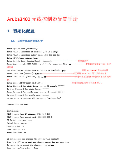
Aruba3400无线控制器配置手册1.初始化配置1.1.无线控制器初始化配置Enter System name [Aruba3400]:Enter VLAN 1 interface IP address [172.16.0.254]:Enter VLAN 1 interface subnet mask [255.255.255.0]:Enter IP Default gateway [none]:Enter Switch Role, (master|local) [master]: ————————————控制器角色Enter Country code (ISO-3166), <ctrl-I> for supported list: cn———————控制器所在国家代码,此选项影响You have chosen Country code CN for China (yes|no)?: yes可用RF channel及功率参数Enter Time Zone [PST-8:0]: UTC8:0——————————————-时区系统(UTC、PST等)及所在时区Enter Time in UTC [06:07:59]: 6:11:30——————————————所选时区系统的标准时间而不是本地时间,Enter Date (MM/DD/YYYY) [8/14/2011]: 否则控制器的时钟可能就不对了。
Enter Password for admin login (up to 32 chars): ******Re-type Password for admin login: ******Enter Password for enable mode (up to 15 chars): ******Re-type Password for enable mode: ******Do you wish to shutdown all the ports (yes|no)? [no]:Current choices are:System name:VLAN 1 interface IP address: 172.16.0.254VLAN 1 interface subnet mask: 255.255.255.0IP Default gateway: noneSwitch Role: masterCountry code: cnTime Zone: UTC8:0Ports shutdown: noIf you accept the changes the switch will restart!Type <ctrl-P> to go back and change answer for any questionDo you wish to accept the changes (yes|no)yesCreating configuration... Done.System will now restart!Shutdown processing started1.2.恢复出厂设置-无线控制器注意以下两条command的区别:(Aruba3400) #write eraseAll the configuration will be deleted. Press 'y' to proceed :Write Erase successful(Aruba3400) #(Aruba3400) #write erase allSwitch will be factory defaulted. All the configuration and databases will be deleted. Press 'y' to proceed :(Aruba3400) #(Aruba3400) #(Aruba3400) #reloadDo you really want to reset the system(y/n): ySystem will now restart!write erase只删除配置文件。
Aruba配置手册大全

第二卷安装Aruba移动边缘系统第2章部署基本移动边缘系统这章主要介绍如何将Aruba移动控制器和Aruba AP接入你的有线网络。
看完这章的介绍以后,你就可以配置AP,同样的介绍在第3卷里。
这章主要介绍了以下几部分:⏹“配置的介绍” 第48页⏹“配置Aruba移动控制器” 第52页⏹“部署APs” 第57页⏹“附加的配置” 第61页配置的介绍这个部分介绍了典型的部署情况和任务,你必须把Aruba移动控制器和Aruba AP接入到你的有线网络。
部署环境一:路由器是控制器和客户端的默认网关在这个部署环境中,Aruba AP和移动控制器连接在相同的子网上,并且使用被指定的子网IP地址。
在AP与控制器中间没有路由器。
AP能够被物理的连接到控制器上。
控制器上的上行端口被连接到2层交换机或者路由器上。
你必须完成下列任务:1. 进行初始化设置●设置VLAN 1的IP地址●设置默认网关的IP地址,将控制器连接到上行的路由器2. 把移动控制器上的上行端口连接到交换机或者路由器的端口上,默认的,控制器上的所有端口都是Access端口并且所有端口都属于同一个VLAN3. 部署AP。
所有的AP会使用Aruba Discovery Protocol(ADP)协议来发现移动控制器。
为所有用户指定VLAN并且配置VLAN 1的SSID。
部署环境二:对于所有客户端来说移动控制器是默认网关在这个部署环境中,Aruba移动控制器和AP在不同的子网中,而且AP在多个子网中。
移动控制器将作为无线网络的一个路由器(移动控制器作为无线客户端的默认网关)。
控制器上的上行端口被连接到2层交换机或路由器上;这是一个属于VLAN 1的Access 端口。
你必须完成下列任务:1. 进行初始化设置●设置VLAN 1的IP地址●设置默认网关的IP地址,将控制器连接到上行的路由器2. 把移动控制器上的接口连接到交换机或者路由器的接口上3. 部署AP。
所有的AP会使用DNS或DHCP来发现移动控制器。
(完整)aruba配置手册

拓扑图如下:客户的要求如下:ap地址通过核心交换机分配,全部在一个vlan中无线用户地址通过核心交换机分配,按照楼层不同,对应不同的vlan,分配不同的地址用户采用web或802.1x认证方式,与内部radius认证服务器联动所有ap均向外公布同一个ssid设备初始化设置拿到设备后,先进行初始化配置,恢复设备到出厂设置状态,在恢复出厂设置后,通过console连接到设备上,按照下面的提示进行初始信息的输入:Enter System name [Aruba5000]: Aruba—masterEnter VLAN 1 interface IP address [172。
16。
0。
254]:Enter VLAN 1 interface subnet mask [255。
255。
255。
0]:Enter IP Default gateway [none]:Enter Switch Role, (master|local) [master]:Enter Country code (ISO-3166), <ctrl—I> for supported list: cnYou have chosen Country code CN for China (yes|no)?: yEnter Time Zone [PST—8:0]:Enter Time in GMT [09:44:27]:Enter Date (MM/DD/YYYY) [3/6/2007]:Enter Password for admin login (up to 32 chars): *****Re—type Password for admin login: *****Enter Password for enable mode (up to 15 chars): ******Re-type Password for enable mode: ******Do you wish to shutdown all the ports (yes|no)?[no]: nCurrent choices are:System name: Aruba800—4VLAN 1 interface IP address: 172。
Aruba无线控制器用户初始配置手册(suning)
苏宁电器Aruba无线控制器用户配置手册Version 1.3苏宁电器Aruba无线控制器用户配置手册一、连接Aruba无线控制器1.将console线RJ45一端连接至无线控制器的SERIAL端口,另一端连接至电脑COM 口(笔记本没有COM口的可以使用USB—COM线).2.打开相应的配置终端软件(可以使用Secure—CRT或者使用系统自带的超级终端软件,建议使用Secure-CRT这款第三方终端软件)3.配置终端软件的参数Secure—CRT配置步骤:协议选择Serial,点击“下一步”端口选择好本电脑上使用的COM接口,波特率选择“9600”,数据流控制选型将前面的勾全部去掉,其它选项保持不变,点击“下一步”点击“完成”即可登录到配置界面。
超级终端配置步骤:点击“开始”〉“所有程序"〉“附件”>“通讯”>“超级终端”在名称一栏自定义输入一个名称,例如:“suning”,点击“确定”在连接时使用选择好相应的COM接口,点击“确定”点击“还原为默认值”,再点击“确定”即可登录到配置界面。
二、配置向导第一次登录控制器会出现配置向导进行简单的配置开机运行到如下图所示,即到了配置向导界面配置如下:Enter System name [Aruba200]:此处直接回车即选择[]内的内容,例如此处回车即选择设备名称为:Aruba200,也可自己自定义系统名称Enter VLAN 1 interface IP address [172。
16。
0.254]:此处直接回车即选择VLAN 1的IP 地址为:172。
16.0。
254,一般此处直接回车,后面可以另行更改Enter VLAN 1 interface subnet mask [255。
255.255.0]:此处直接回车即选择VLAN 1的IP 地址的子网掩码为:255.255.255。
0Enter IP Default gateway [none]:此处为指定控制器的网关地址,即路由地址,一般这边不指定,等进入系统后重新配置指定Enter Switch Role,(master|local) [master]:此处为指定控制器角色,一般默认为master,可直接回车到下一步Enter Country code (ISO—3166),〈ctrl—I> for supported list:此处为指定国家代码,中国即输入“CN"You have chosen Country code CN for China (yes|no)?:此处为让您确认是否为中国,可直接“yes”到下一步Enter Time Zone [PST-8:0]:此处为指定时区,一般我们指定为“GMT+8:0”Enter Time in UTC [11:44:55]:此处为指定时间,我们可根据当时北京时间进行配置Enter Date (MM/DD/YYYY)[11/22/2010]:此处为配置日期,月/日/年份Enter Password for admin login (up to 32 chars):此处为配置admin登录密码,自定义Re—type Password for admin login:重新确认admin登录密码Enter Password for enable mode (up to 15 chars):指定enable密码Re-type Password for enable mode:重新确认enable密码Do you wish to shutdown all the ports (yes|no)?[no]:此处为询问您是否想shutdown所有端口,默认配置为“no”,一般选择默认配置直接回车Do you wish to accept the changes (yes|no)此处询问你是否接受刚才的配置,直接“yes”此时控制器会重新启动,启动完之后便可进入系统。
ARUBA交换机配置模板

ARUBA交换机配置模板初始账号admin12口交换机admin初始密码admin123admin123初始账号enable enable初始密码enable enabley yyes yes管理vlan158812创建默认trunk0/0/23,0/0/22,0/1/0,0/1/10/0/11,0/1/0,0/1/1 管理IP172.31.99.19910.20.12.34子网掩码255.255.255.0255.255.252.0网关172.31.99.110.20.12.1DNS8.8.8.8nocnyes210.34.213.3时区UTC+8:0cst+8:0修改密码admin123!admin123!再次输入admin123!admin123!enable enableenable enableyes yes进入全局模式configure t configure t修改交换机命名hostname Xxx-HKXY-4F-dongqiu-A1500POE hostname JXL3#-WIFI-JKC-03-12P 开启Telnet功能telnet cli telnet cli创建新用户mgmt-user cacti rootcactiadmin123cactiadmin123!打开SNMP协议snmp-server snmp-serversnmp-server enable trap snmp-server enable trapsnmp-server community public snmp-server community public 创建级联口模板interface-profile switching-profile trunk interface-profile switching-pr switchport-mode trunk switchport-mode trunktrunk allowed vlan all trunk allowed vlan all!!VLAN 156VLAN 812!!创建vlan模板interface-profile switching-profile vlan156interface-profile switching-pr 关联VLAN ACcess-vlan 156ACcess-vlan 812!!创建POE 模板interface-profile poe-profile ap interface-profile poe-profile 启用POE功能enable enable!!进入接口模式interface gigabitethernet 0/0/0interface gigabitethernet 0/0/应用VLAN switching-profile vlan156switching-profile vlan812启用接口POE功能poe-profile ap poe-profile apinterface gigabitethernet 0/0/1interface gigabitethernet 0/0/ switching-profile vlan156switching-profile vlan812poe-profile ap poe-profile apinterface gigabitethernet 0/0/2interface gigabitethernet 0/0/ switching-profile vlan156switching-profile vlan812poe-profile ap poe-profile apinterface gigabitethernet 0/0/3interface gigabitethernet 0/0/ switching-profile vlan156switching-profile vlan812poe-profile ap poe-profile apinterface gigabitethernet 0/0/4interface gigabitethernet 0/0/ switching-profile vlan156switching-profile vlan812poe-profile ap poe-profile apinterface gigabitethernet 0/0/5interface gigabitethernet 0/0/ switching-profile vlan156switching-profile vlan812poe-profile ap poe-profile apinterface gigabitethernet 0/0/6interface gigabitethernet 0/0/ switching-profile vlan156switching-profile vlan812poe-profile ap poe-profile apinterface gigabitethernet 0/0/7interface gigabitethernet 0/0/ switching-profile vlan156switching-profile vlan812poe-profile ap poe-profile apinterface gigabitethernet 0/0/8interface gigabitethernet 0/0/ switching-profile vlan156switching-profile vlan812poe-profile ap poe-profile apinterface gigabitethernet 0/0/9interface gigabitethernet 0/0/ switching-profile vlan156switching-profile vlan812poe-profile ap poe-profile apinterface gigabitethernet 0/0/10interface gigabitethernet 0/0/ switching-profile vlan156switching-profile vlan812 poe-profile ap poe-profile apinterface gigabitethernet 0/0/11interface gigabitethernet 0/0/ switching-profile vlan156switching-profile trunk poe-profile ap!interface gigabitethernet 0/0/12delete stacking interface stac switching-profile vlan156delete stacking interface stac poe-profile ap interface gigabitethernet 0/1/ interface gigabitethernet 0/0/13switching-profile trunk switching-profile vlan156interface gigabitethernet 0/1/ poe-profile ap switching-profile trunk interface gigabitethernet 0/0/14write m switching-profile vlan156SHOW IP INterface Brief poe-profile ap SHOW IP-Profileinterface gigabitethernet 0/0/15SHOW VLANswitching-profile vlan156show lldp neipoe-profile ap SHOW TRUNKinterface gigabitethernet 0/0/16!switching-profile vlan156poe-profile apinterface gigabitethernet 0/0/17switching-profile vlan156poe-profile apinterface gigabitethernet 0/0/18switching-profile vlan156poe-profile apinterface gigabitethernet 0/0/19switching-profile vlan156poe-profile apinterface gigabitethernet 0/0/20switching-profile vlan156poe-profile apinterface gigabitethernet 0/0/21switching-profile vlan156poe-profile apinterface gigabitethernet 0/0/22switching-profile trunk!interface gigabitethernet 0/0/23switching-profile trunk!删除堆叠口delete stacking interface stack 1/2删除堆叠口delete stacking interface stack 1/3interface gigabitethernet 0/1/2设置trunk switching-profile trunkinterface gigabitethernet 0/1/3switching-profile trunk!snmp-server community xxxpublic view ALLsnmp-server group xxxpublic v1 read ALLsnmp-server group xxxpublic v2c read ALL 保存write m 查看交换机IP地址SHOW IP INterface Brief查看网关IP地址SHOW IP-Profile查看VLAN SHOW VLAN发现邻居设备show lldp neishow trunkping 172.31.99.11/1JXL3#-WIFI-JKC-03-12Pver enable trapver community publice-profile switching-profile trunk rt-mode trunklowed vlan alle-profile switching-profile vlan812 e-profile poe-profile ap e gigabitethernet 0/0/0g-profile vlan812e gigabitethernet 0/0/1g-profile vlan812e gigabitethernet 0/0/2g-profile vlan812e gigabitethernet 0/0/3g-profile vlan812e gigabitethernet 0/0/4g-profile vlan812e gigabitethernet 0/0/5g-profile vlan812e gigabitethernet 0/0/6g-profile vlan812e gigabitethernet 0/0/7g-profile vlan812e gigabitethernet 0/0/8g-profile vlan812e gigabitethernet 0/0/9g-profile vlan812e gigabitethernet 0/0/10g-profile vlan812e gigabitethernet 0/0/11g-profile trunktacking interface stack 1/1 tacking interface stack 1/3 e gigabitethernet 0/1/1g-profile trunke gigabitethernet 0/1/3g-profile trunkINterface Brief。
Aruba控制器操作配置模版中文
1.Mgmt用户设置设置mgmt用户ssh登录的方式:是证书还是用户名与密码ssh mgmt-auth [public-key |username/password]mgmt-user ssh-pubkey client-cert <certificate> <username> <role>mgmt用户验证使用外部认证服务器:aaa authentication-server radius rad1host <ipaddr>key――――aaa server-group corp_radauth-server rad1-------------------------aaa authentication mgmtdefault-role rootenableserver-group corp_rad禁用本地认证数据库mgmt-user localauth-disable设置用户超时退出loginsession timeout <value> //CLI下web-server sessiontimeout <session-timeout> //webUI下1.1配置mgmt的tacacs认证The pre-defined roles for the controllers are:1.root - super user role2.guest-provisioning - guest provisioning rolework-operations - Network operator role4.read-only - Read only role5.location-api-mgmt - Location API Management Roleaaa authentication-server tacacs TACACS-SERVERhost TACACS_SERVER_IPkey PRESHARE_KEYsession-authorization!aaa server-group TACACS-SERVER-GRPauth-server TACACS-SERVER!aaa tacacs-accounting server-group TACACS-SERVER-GRP mode enable command[all|action|configuration|show]aaa authentication mgmtserver-group TACACS-SERVER-GRPenable!2.系统默认的角色与策略:默认的策略:ip access-list session control,validuser,allowall,icmp-acl, logon-control, captiveportal,tftp-acl, https-acl, http-acl, dhcp-acl, ap-acl,默认的角色:user-role ap-role, voice, guest-logon(portal认证), guest, authenticated,logon――――――――――――――――――――――――――――――――――――3.本地数据库操作local-userdb export <filename>local-userdb import <filename>local-userdb add {generate-username|username <name>} {generate-password|password <password>}――――――――――――――――――――――――――――――――――――――――4.配置DHCP服务:ip dhcp pool user-pooldefault-router 192.168.100.1dns-server 192.168.100.1network 192.168.100.0 255.255.255.0!service dhcpip dhcp excluded-address 192.168.100.1 192.168.100.10 ――――――――――――――――――――――――――――――――――――5.配置带宽:aaa bandwidth-contract BC512_up kbps 512user-role web-guestbw-contract BC512_up per-user upstream ―――――――――――――――――――――――――――――――――――――6.策略:限制访问内网netdestination “Internal Network”network 10.0.0.0 255.0.0.0network 172.16.0.0 255.255.0.0network 192.168.0.0 255.255.0.0ip access-list session block-internal-accessuser alias “Internal Network” any deny ―――――――――――――――――――――――――――――――――――――7.配置portal认证:外置portal时:netdestination portal-serverhost 10.50.22.221ip access-list session abc-portal-acluser alias portral-server svc-http permitaaa authentication captive-portal c-portaldefault-role employeeserver-group cp-srvlogin-page http://192.168.100.10/test.phpuser-role logoncaptive-portal c-portalsession-acl abc-portal-aclaaa profile aaa_c-portalinitial-role logonwlan ssid-profile ssid_c-portalessid c-portal-apwlan virtual-ap vp_c-portalaaa-profile aaa_c-portalssid-profile ssid_c-portalvlan 20portal下增加白名单:(host)(config)# netdestination "Mywhite-list"(host)(config)#name (host)(config)#name (host) (config) #aaa authentication captive-portal default(host)(Captive Portal Authentication Profile "default")#white-list Mywhite-list注意:如果在一台控制器配置多个captiveportal的Virtaul AP时,每个captiveportal必须分别配置不同的initial role和user role、cp profile、AAA profile与ssid profile;8.配置Air time fair(Aruba651) (Traffic management profile "test") #shaping-policy fair-access (Aruba651) (Traffic management profile "test") #exit(Aruba651) (config)ap-group demo-group(Aruba651) (AP group " demo-group") #dot11g-traffic-mgmt-profile test(Aruba651) (AP group "demo-group") #9.配置LACP:LACP默认不生效每台设备最多创建8个组(0-7),每个组最多允许8个端口加入,所有端口的属性要相同;1、Enable LACP and configure the per-port specific LACP. The group number range is 0 to 7.lacp group <group_number> mode {active | passive}? Active mode—the interface is in active negotiating state. LACP runs on any link that is configured to be in the active state. The port in an active mode also automatically initiates negotiations with otherports by initiating LACP packets.? Passive mode—the interface is not in an active negotiating state. LACP runs onany link that is configured in a passive state. The port in a passive mode responds to negotiations requests from other ports that are in an active state. Ports in passive state respond to LACP packets.注意:passive模式的端口不能与另一个passive 模式的端口建立起来;2. Set the timeout for the LACP session. The timeout value is the amount of time thata port-channelinterface waits for a LACPDU from the remote system before terminating the LACP session. The defaulttime out value is long (90 seconds); short is 3 seconds,默认为longlacp timeout {long | short}3. Set the port priority.lacp port-priority <priority_value>The higher the priority value the lower the priority. Range is 1 to 65535 and default is 255.4.加入端口中interface fastethernet 1/1lacp timeout shortlacp group 0 mode active―――――――――――――――――――――――――――――――――――――――――10.配置RAP(remote ap)在控制器上配置VPN、AP通过认证后的地址池,及isakmp的共享密码;注意地址池为RAP的管理地址,如其他网管要直接ping通RAP,需要将此地址段配置静态路由;vpdn group l2tpppp authentication PAPip local pool <pool> <start-ipaddr> <end-ipaddr>crypto isakmp key <key> address 0.0.0.0 netmask 0.0.0.0在控制器上配置服务器组,RAP通过username/password方式接入,并在服务器上增加用户名与密码,此用户名/密码用于L2TP/PAP认证 (如果采用证书方式,此步可以省略)aaa server-group <group>auth-server <server>aaa authentication vpn default-rapdefault-role <role>server-group <group>local-userdb add username rapuser1 password <password>配置remote ap的VAP:wlan ssid-profile <profile>essid <name>opmode <method>wpa-passphrase <string> (if necessary)配置用户角色,用于dot1x-default-role(cli) #netdestination corp(cli) (config-dest) # network 10.3.10.0 255.255.255.0(cli) (config-dest) # !ip access-list session Remote_Enterprise_aclany any svc-dhcp permituser alias corp any permitalias corp user any permituser network 224.0.0.0 255.0.0.0 any permitalias coopr alias corp any permituser any any route src-nat(cli) # user-role corpsplit(cli) (config-role) # session-acl Remote_Enterprise_acl(cli) (config-role) # !配置aaa profile可用于split-tunnel时用户角色策略指定aaa profile <profile>authentication-dot1x <profile>dot1x-default-role <role>dot1x-server-group <group>(cli) # wlan virtual-ap split(cli) # vlan X <-- Clients get IP addr. from VLAN X(cli) # forward-mode split-tunnelaaa-profile <profile>rap-operation {always|backup|persistent}配置RAP的有线端口:ap wired-ap-profile Wired_Branch_ap_profilewired-ap-enableforward-mode split-tunnelswitchport access vlan 128!ap wired-port-profile Wired_Branch_port_profileaaa-profile Remote_Ent_aaa_profilewired-ap-profile Wired_Branch_ap_profile配置RAP做DHCP serverap system-profile APGroup1_sys_profilelms-ip 63.82.214.194rap-dhcp-server-vlan 177rap-dhcp-server-id 192.168.177.1rap-dhcp-default-router 192.168.177.1rap-dhcp-pool-start 192.168.177.100rap-dhcp-pool-end 192.168.177.254!ap-group <name>virtual-ap <name>在webUI界面对AP进行provision,从AC上获取IP,修改为remote模式,AP会重启11.配置MAC认证完整例子RADIUS Server Definition:服务器认证aaa authentication-server radius "amigopod"host "172.16.0.20"key f0e40f33109cd5f863a77327072720aaa4785eff2ca57800nas-identifier "Aruba651"nas-ip 172.16.0.254!aaa server-group "amigopod-srv"auth-server amigopod!aaa rfc-3576-server "172.16.0.20"key 10795ff19c00465dd0b0824e562103bee537be631e5bc876MAC Authentication Profile:MAC认证aaa authentication mac "amigopod-mac"case upperdelimiter dashAAA Profile:aaa profile "amigopod-aaa"authentication-mac "amigopod-mac"mac-default-role "authenticated"mac-server-group "amigopod-srv"radius-accounting "amigopod-srv"rfc-3576-server "172.16.0.20"Captive Portal Profile:aaa authentication captive-portal "amigopod-cp"server-group "amigopod-srv"redirect-pause 3no logout-popup-windowprotocol-httplogin-page "http://172.16.0.20/aruba_login.php"Netdestination Alias for Amigopod:netdestination amigopodhost 172.16.0.20Access Policy to allow redirect to Amigopod:允许的aclip access-list session allow-amigopoduser alias amigopod svc-http permituser alias amigopod svc-https permitInitial Role with Captive Portal enabled:配置initial角色user-role logoncaptive-portal "amigopod-cp"access-list session logon-controlaccess-list session allow-amigopodaccess-list session captiveportalPost Authentication Role for MAC Authentication:配置MAC认证角色user-role MAC-Guestaccess-list session allowallSSID Profile:wlan ssid-profile "MAC-Auth-CP"essid "amigo-MAC-CP"Virtual AP:wlan virtual-ap "MAC-Auth-CP"aaa-profile "amigopod-aaa"ssid-profile "MAC-Auth-CP"12.配置LDAP认证服务器Portal认证aaa authentication-server ldap "aruba-ldap"host 10.1.1.50admin-dn "cn=ldapquery2, cn=Users, dc=arubanetworks, dc=com" admin-passwd "Zaq1xsw2"base-dn "ou=Corp, dc=arubanetworks, dc=com"!aaa server-group "aruba-ldap"auth-server aruba-ldapset role condition memberOf contains "dl-seonly" set-value root !如果将ldap认证应用于无线用户802.1x,必须使用eap-gtc方式aaa authentication dot1x "dot1x_prof-yxy03"termination enabletermination eap-type eap-peaptermination inner-eap-type eap-gtc!aaa authentication mgmt //应用在管理用户default-role "no-access"server-group "aruba-ldap"enable!注意:使用802.1x认证时不能用LDAP认证服务器;但portal认证时可以;13.有线端口NAT!ip NAT pool Dell-AirWave 63.80.98.56 63.80.98.56 172.16.0.246ip NAT pool SE-WebServer 63.80.98.59 63.80.98.59 172.16.0.16ip NAT pool PDL-eTips 63.80.98.61 63.80.98.61 172.16.0.15ip NAT pool PDL-Clearpass 63.80.98.60 63.80.98.60 172.16.0.13ip NAT pool PDL-AirWave 63.80.98.49 63.80.98.49 172.16.0.252!netdestination PDL-Airwave-Livehost 63.80.98.49!netdestination IPCommshost 64.154.41.150!netdestination SE-WebServerhost 63.80.98.59!netdestination Live-IPhost 63.80.98.41!netdestination PDL-eTipshost 63.80.98.61!netdestination Dell-Airwave-Livehost 63.80.98.56!netdestination PDL-ClearPasshost 63.80.98.60!ip access-list session OUTSIDE-POLICYalias IPComms alias Live-IP udp 4569 dst-nat ip 172.16.0.11 4569 classify-media queue highalias IPComms alias Live-IP udp 5060 dst-nat ip 172.16.0.11 5060 classify-media queue highalias IPComms alias Live-IP udp 5061 dst-nat ip 172.16.0.11 5061 classify-media queue highalias IPComms alias Live-IP udp 5062 dst-nat ip 172.16.0.11 5062 classify-media queue highany alias Live-IP tcp 4343 permitany alias Live-IP udp 4500 permitany alias Live-IP svc-ssh permitany alias Live-IP svc-http permitany alias Live-IP svc-https permitany alias Live-IP udp 500 permitany alias Live-IP svc-icmp permitany alias Live-IP tcp 4345 dst-nat ip 172.16.0.242 443any alias Live-IP tcp 4346 dst-nat ip 172.16.0.242 22any alias Dell-Airwave-Live svc-https dst-nat ip 172.16.0.246 443any alias Dell-Airwave-Live svc-http dst-nat ip 172.16.0.246 80any alias PDL-Airwave-Live svc-https dst-nat ip 172.16.0.252 443any alias PDL-Airwave-Live svc-http dst-nat ip 172.16.0.252 80any alias SE-WebServer svc-http dst-nat ip 172.16.0.16 80any alias SE-WebServer svc-https dst-nat ip 172.16.0.16 443any alias SE-WebServer svc-ssh dst-nat ip 172.16.0.16 22any alias SE-WebServer udp 5900 dst-nat ip 172.16.0.16 5900any alias PDL-eTips svc-http dst-nat ip 172.16.0.15 80any alias PDL-eTips svc-https dst-nat ip 172.16.0.15 443any alias PDL-ClearPass svc-https dst-nat ip 172.16.0.13 443any alias PDL-ClearPass svc-http dst-nat ip 172.16.0.13 80!interface fastethernet 2/0description "OUTSIDE-INTERNET"trustedip access-group OUTSIDE-POLICY sessionswitchport access vlan 10!14.用户通过有线端口portal认证,不同的IP用户可以分别认证,所有有线口共用一个认证方式aaa profile "cppm"initial-role "cp-guest"radius-accounting "amigopod-sg"radius-interim-accountingrfc-3576-server "222.190.16.186" //amigopod地址aaa authentication wired //有线端口启用认证profile "cppm"interface gigabitethernet 1/6 //有张端口untrusted vlan 1000description "connect_to_H3C"trusted vlan 1-999,1001-4094switchport access vlan 1000针对某一vlan启用portal认证vlan 20 wired aaa-profile cppm15.配置AP以太口对于有两个以太口的AP,如125与135系列,除了一个以太口用于AC互连外,另外一个以太口可以连接终端或串联AP;(1)连接终端时:创建wired-ap profileap wired-ap-profile "cppm"wired-ap-enableswitchport access vlan 11trusted创建wired-port profileap wired-port-profile "cppm"wired-ap-profile "cppm"将profile加入到group中ap-group "test"enet1-port-profile "cppm"注意:如果端口为untrusted,需要在wired-port profile中加入aaa profile16.配置VIA(host) (config)# license add <key>(1)Create VIA roles(host) (config) #user-role example-via-role(host) (config-role) #access-list session "allowall" position 1(host) (config-role) #ipv6 session-acl "v6-allowall" position 2(2)Create VIA authentication profiles(host) (config) #aaa server-group "via-server-group"(host) (Server Group "via-server-group") #auth-server "Internal" position 1 (host) (config) #aaa authentication via auth-profile default(host) (VIA Authentication Profile "default") #default-role example-via-role(host) (VIA Authentication Profile "default") #desc "Default VIAAuthenticationProfile"(host) (VIA Authentication Profile "default") #server-group "via-server-group"(3)Create VIA connection profiles(host) (config) #aaa authentication via connection-profile "via"(host) (VIA Connection Profile "via") #server addr 202.100.10.100 internal-ip10.11.12.13 desc "VIA Primary Controller" position 0(host) (VIA Connection Profile "via") #auth-profile "default" position 0(host) (VIA Connection Profile "via") #tunnel address 10.0.0.0 netmask255.255.255.0(host) (VIA Connection Profile "via") #split-tunneling(host) (VIA Connection Profile "via") #windows-credentials //使用windows 的帐号登录(host) (VIA Connection Profile "via") #client-netmask 255.255.255.255 (host) (VIA Connection Profile "via") #no ikev2-proto //local数据库不支持ikeV2(host) (VIA Connection Profile "via") #dns-suffix-list (host) (VIA Connection Profile "via") #support-email via-support@(host) (VIA Connection Profile "via") #client-wlan-profile"via_corporate_wpa2"position 0(4)Configure VIA web authentication(host) (config) #aaa authentication via web-auth default(host) (VIA Web Authentication "default") #auth-profile default position 0(5)Associate VIA connection profile to user role(host) (config) #user-role "example-via-role"(host) (config-role) #via "via"You can have only one profile (default) for VIA web authentication.(6)Configure VIA client WLAN profiles(host) (config) #wlan ssid-profile "via_corporate_wpa2"(host) (SSID Profile "via_corporate_wpa2") #essid corporate_wpa2(host) (SSID Profile "via_corporate_wpa2") #opmode wpa2-aes(host) (SSID Profile "via_corporate_wpa2") #wlan client-wlan-profile"via_corporate_wpa2"(host) (VIA Client WLAN Profile "via_corporate_wpa2") #ssid-profile"via_corporate_ssid"(7)crypto isakmp key 123456 address 0.0.0.0 netmask 0.0.0.0(8)。
ARUBA3600简明配置手册
ARUBA3600简明配置手册目录1、图表 (6)1.1 AG Group内容 (6)1.2 Profile关系图 (6)1.3 用户认证过程 (7)2、建立Portal认证 (8)步骤1 新建一个AP group,命名为test-group (8)步骤2将AP加入到AP Group中 (8)步骤3 新建一个Virtual AP,命名为test-vap-web (10)步骤4 将Virtual AP加入到Vlan 1 (11)步骤5 新建一个SSID Profile (11)步骤6 新建一个AAA Profile (12)步骤7 在Initial DB中新建一个用户 (12)步骤8 新建一个Portal Profile,命名为test-portal, (13)步骤9 将上面建立好的P ortal Profile关联到logon这个Role中 (13)步骤10 将AAA Profile关联到AP Group中 (14)步骤11 在认证界面中输入用户名密码进行登录 (14)步骤12 如果要更改WEB认证界面,则进行如下操作 (15)3、建立WEP认证 (17)步骤1 建立AP Group,命名为test-group,如之前已建立则无需建立 (17)步骤2将AP加入到AP Group中 (17)步骤3 新建一个Virtual AP,命名为test-vap-wep (18)步骤4 将Virtual AP加入到Vlan 1 (19)步骤5 新建一个SSID Profile (20)4、建立WP A2认证 (22)步骤1 建立AP Group,命名为test-group,如之前已建立则无需建立 (22)步骤2将AP加入到AP Group中 (22)步骤3 新建一个Virtual AP,命名为test-vap-wpa2 (23)步骤4 将Virtual AP加入到Vlan 1 (24)步骤5 关联一个AAA Profile (25)步骤6 新建一个SSID Profile (25)步骤7 验证以上两种认证方式 (26)5、建立802.1X认证 (28)步骤1 建立AP Group,命名为test-group,如之前已建立则无需建立 (28)步骤2将AP加入到AP Group中 (28)步骤3 新建一个Virtual AP,命名为test-vap-1x (29)步骤4 将Virtual AP加入到Vlan 1 (30)步骤5 新建一个SSID Profile (30)步骤6 新建一个L2 Authentication AAA Profile,命名为test-L2a-1x (31)步骤7 在Internal DB中新建一个用户 (32)步骤8 新建一个AAA Profile (32)步骤9 将各Profiles关联起来 (33)6、同一SSID中为不同用户配置不同的权限 (37)步骤1 在Internal DB中添加用户 (37)步骤2 测试 (37)7、设置用户期限 (39)步骤1 在Internal DB中新建一个账户 (39)步骤2 连接该SSID (40)步骤3 打开IE使用刚创建的用户登录 (40)步骤7 继续使用之前的用户登录,提示认证失败,该用户在Internal DB中已自动删除 (42)8、多级管理员 (43)9、根据MAC地址(2层)设置策略 (44)步骤1 新建一条策略 (44)步骤2 根据需要选择策略的类型 (46)步骤3 设置简单访问控制策略 (47)步骤4新建一个AAA Profile,命名为“test-aaa-open” (51)步骤5 调用之前创建好的Role (51)步骤6 如果做了认证,则在认证方式那里调用Role (52)步骤7 新建一个Virtual AP (54)步骤8 将Virtual AP划分到Vlan 1 (55)步骤9新建一个SSID Profile,命名为test-ssid-open (56)步骤10 调用前面创建的AAA Profile (57)步骤11 查看结果 (57)10、设定区域管理 (59)步骤1 新建多个AP Group,命名为test-group1、test-group2, (59)步骤2 新建一个Virtual AP,命名为test-vap-area1 (59)步骤3 将Virtual AP加入到相应Vlan (59)步骤4 建立多个AAA Profile,命名为test-aaa-area1、test-aaa-area2...... . (61)步骤5 将每个AAA Profile与对应的Server Group关联起来,以实现不同的Server Rule (61)步骤6 再将各AAA Profile与对应的Virtual AP关联起来 (62)步骤7 按区域将AP加入到各AP Group中 (62)步骤8 检验配置结果,使用相同的SSID在不同的地理区域登入网络所获得权限是不一样的,从而实现了区域管理 (64)11、配置日志服务器 (65)步骤1 设置日志服务器的地址和权限等级 (65)12、带宽限制 (66)步骤1 进入User Roles配置界面 (66)步骤2 新建一条带宽限制规则 (66)步骤3 应用刚添加的规则 (67)1、图表1.1 AG Group内容1.2 Profile关系图1.3 用户认证过程2、建立Portal认证步骤1 新建一个AP group,命名为test-groupConfiguration>AP Configuration>AP Group>输入名字点Add步骤2将AP加入到AP Group中选中AP,点击“Provision”选择要加入的组点击“Apply and Reboot”步骤3 新建一个Virtual AP,命名为test-vap-web Configuration>AP Configuration>AP Group> 找到步骤1中创建的组>点Edit点击APPL Y确认添加步骤4 将Virtual AP加入到Vlan 1Configration>AP Configuration>AP Group>test-vap-web步骤5 新建一个SSID Profile点击左边栏中对应的Virtual AP名称>SSID Profile>NEW命名为test-ssid-web>Apply确认步骤6 新建一个AAA ProfileConfiguration>Security>Authentication>AAA Profiles>Add>命名为test-aaa-web>Apply确认步骤7 在Initial DB中新建一个用户Security > Authentication > Servers>Initial DB>ADD,输入用户名密码步骤8 新建一个P ortal Profile,命名为test-portal,uration>Security > Authentication >L3 Authentication>Capture Portal Authentication Profile>输入名字点Add步骤9 将上面建立好的Portal Profile关联到logon这个Role中Configuration>Access Contral>Capture Portal Profile>选test-portal点change>Apply确认步骤10 将AAA Profile关联到AP Group中Configuration>AP Configuration>AP Group>Edit>AAA Profile> 选test-aaa-web>Apply确认步骤11 在认证界面中输入用户名密码进行登录步骤12 如果要更改WEB认证界面,则进行如下操作方法一:使用Aruba控制器中内置的网页界面Maintenance>Captive Portal > Customize Login Page,选择所要更改的Profile和界面,该界面可以进行部分自定义方法二:使用客户自己定制的页面Maintenance>Captive Portal > Upload Custom Login Page,将自己定制的页面导入到指定的使用web portal认证的ssid选择需要修改登陆界面的SSID选择定制的页面选择“Captive portal login”恢复到默认界面3、建立WEP认证步骤1 建立AP Group,命名为test-group,如之前已建立则无需建立Configuration>AP Configuration>AP Group>输入名字点Add步骤2将AP加入到AP Group中选中AP,点击“Provision”选择要加入的组点击“Apply and Reboot”步骤3 新建一个Virtual AP,命名为test-vap-wepConfiguration>AP Configuration>AP Group>Edit>Virtual AP>NEW>添入名字点AddApply确认步骤4 将Virtual AP加入到Vlan 1Configuration>AP Configuration>AP Group>test-vap-wep步骤5 新建一个SSID Profile点击左边栏中对应的Virtual AP名称>SSID Profile>NEW命名为test-ssid-wep>Apply确认输入SSID Profile名称test-ssid-wep,输入SSID名称test-ssid-wep点选认证方式为wep,并填写密码,点击“Apply”,配置完成4、建立WPA2认证步骤1 建立AP Group,命名为test-group,如之前已建立则无需建立Configuration>AP Configuration>AP Group>输入名字点Add步骤2将AP加入到AP Group中选中AP,点击“Provision”选择要加入的组点击“Apply and Reboot”步骤3 新建一个Virtual AP,命名为test-vap-wpa2Configuration>AP Configuration>AP Group>Edit>Virtual AP>NEW>添入名字点Add步骤4 将Virtual AP加入到Vlan 1Configuration>AP Configuration>AP Group>test-vap-wpa2步骤5 关联一个AAA ProfileConfiguration>Security>Authentication>AAA Profiles>下拉框选中default-dot1x-psk>Apply确认步骤6 新建一个SSID Profile点击左边栏中对应的Virtual AP名称>SSID Profile>NEW命名为test-ssid-wpa2>Apply确认, 输入SSID Profile名称test-ssid-wpa2,输入SSID名称test-ssid-wpa2点选认证方式为WPA2-PSK,并填写密码,点击“Apply”,配置完成步骤7 验证以上两种认证方式打开windows无线管理,选择test-ssid-wep或test-ssid-wpa2输入密码成功连接5、建立802.1X认证步骤1 建立AP Group,命名为test-group,如之前已建立则无需建立Configuration>AP Configuration>AP Group>输入名字点Add步骤2将AP加入到AP Group中选中AP,点击“Provision”选择要加入的组点击“Apply and Reboot”步骤3 新建一个Virtual AP,命名为test-vap-1xConfiguration>AP Configuration>AP Group>Edit>Virtual AP>NEW>添入名字点AddConfiguration>AP Configuration>AP Group>test-vap-1x步骤5 新建一个SSID Profile点击左边栏中对应的Virtual AP名称>SSID Profile>NEW命名为test-ssid-1x>Apply确认, 输入SSID Profile名称test-ssid-1x,输入SSID名称test-ssid-1x,802.11 Security选WPA2步骤6 新建一个L2 Authentication AAA Profile,命名为test-L2a-1x点击Security > Authentication > L2 Authentication,输入名称点Add点击该Profile,勾选Termination,Apply确认步骤7 在Internal DB中新建一个用户点击Security > Authentication > Servers > Internal DB>ADD User新建一个用户步骤8 新建一个AAA ProfileConfiguration>Security>Authentication>AAA Profiles>Add>命名为test-aaa-1x>Apply确认步骤9 将各Profiles关联起来点击左边该Profile关联之前创建的802.1X Authentication Profile点击802.1X Authentication Server Group,关联Internal点击Configuration > AP Group > Edit "test-group" > AAA Profile,关联之前创建的AAA Profile步骤10 验证802.1X认证方式将终端网卡的配置成802.1X认证方式,然后搜索该AP输入用户名密码连接成功6、同一SSID中为不同用户配置不同的权限步骤1 在Internal DB中添加用户点击ADD User建立两个用户用户名test1 密码123456 登入后Role为authenticated用户名test2 密码123456 登入后Role为guest步骤2 测试使用WEB认证分别用两个账户登录使用test1登入后,用户得到的Role为authenticated使用test2登入后,用户得到的Role为guest7、设置用户期限步骤1 在Internal DB中新建一个账户Security > Authentication > Servers > Internal DB > ADD User输入用户名、密码、用户角色和过期时间,Apply保存步骤2 连接该SSID刚连入后用户角色为logon步骤3 打开IE使用刚创建的用户登录登录后用户角色为authenticated到达设定的过期时间后,该用户角色又变为logon步骤7 继续使用之前的用户登录,提示认证失败,该用户在Internal DB中已自动删除8、多级管理员Management > Administration > Add 输入用户名、密码和权限角色名称说明root 该角色允许管理控制器的所有功能read-only 该角色只允许命令行界面的show命令和查看web管理界面的Monitoring页面。
Aruba快速配置手册
Aruba快速配置手册测试环境:连接在同一台交换机上面AP93 ip:172.16.20.254/244Aruba-650 VLAN 1:192.168.16.0/24AP VLAN 20:172.16.20.0/24User VLAN 30:172.16.30.1/241、Aruba-650初始化配置基本配置成功之后,会提示你自动重启2、通过web界面登录,浏览器输入https://192.168.16.1633、配置Aruba-650 上联端口的接入模式为trunk,允许所有vlan 通过(Aruba650) (config) #interface gigabitethernet 1/0(Aruba650) (config-if)#switchport mode trunk(Aruba650) (config-if)#switchport trunk allowed vlan all4、Aruba650配置DHCP,其中VLAN 20:172.16.20.0/24、AC的VLAN1:192.168.16.0/24、USER的VLAN 30:172.16.30.0/24;配置三个DHCP (Aruba650) (config) #vlan 20(Aruba650) (config) #interface vlan 20(Aruba650) (config-subif)#ip address 172.16.20.1 255.255.255.0(Aruba650) (config-subif)#operstate up(Aruba650) (config-subif)#no shut(Aruba650) (config-subif)#exit(Aruba650) (config) #ip dhcp pool ap(Aruba650) (config-dhcp)#network 172.16.20.0 255.255.255.0(Aruba650) (config-dhcp)#default-router 172.16.20.1(Aruba650) (config-dhcp)#dns-server 61.177.7.1(Aruba650) (config-dhcp)#exit(Aruba650) (config) #service dhcp(Aruba650) (config) #vlan 30(Aruba650) (config) #interface vlan 30(Aruba650) (config-subif)#ip address 172.16.30.1 255.255.255.0 (Aruba650) (config-subif)#operstate up(Aruba650) (config-subif)#no shut(Aruba650) (config-subif)#exit(Aruba650) (config) #ip dhcp pool user_client(Aruba650) (config-dhcp)#network 172.16.30.0 255.255.255.0 (Aruba650) (config-dhcp)#default-router 172.16.30.1(Aruba650) (config-dhcp)#dns-server 61.177.7.1查看已配置的DHCP,show ip dhcp database(Aruba650) (config) #show ip dhcp databaseDHCP enabled# apsubnet 172.16.20.0 netmask 255.255.255.0 {option vendor-class-identifier "ArubaAP";option vendor-encapsulated-options "192.168.16.163";option domain-name-servers 61.177.7.1;option routers 172.16.20.1;range 172.16.20.2 172.16.20.254;authoritative;}# user_clientsubnet 172.16.30.0 netmask 255.255.255.0 {option vendor-class-identifier "ArubaAP";option vendor-encapsulated-options "192.168.16.163";option domain-name-servers 61.177.7.1;option routers 172.16.30.1;range 172.16.30.2 172.16.30.254;authoritative;}5、开启Aruba650的telnet端口,telnet cli6、新增的SSID的模式为open定义aaa profile(Aruba650)(config)#aaa profile open-aaa(Aruba650) (AAA Profile "open-aaa") #Initial-role authenticated //默认为logon 打开IE 会有问题(Aruba650) (AAA Profile "open-aaa") #exit定义ssid profile(Aruba650) (config)# wlan ssid profile open-ssid(Aruba650) (SSID Profile "open-ssid") #essid Aruba-AP //定义ssid名字(Aruba650) (SSID Profile "open-ssid") #opmod opensystem //定义加密方式(Aruba650) (SSID Profile "open-ssid") #exit定义virtual-ap profile(Aruba650) (config) #wlan virtual-ap open-vap(Aruba650) (Virtual AP profile "open-vap") #aaa prolife open-aaa //关联aaa profile(Aruba650) (Virtual AP profile "open-vap") #ssid profile open-ssid //关联ssid profile(Aruba650) (Virtual AP profile "open-vap") #vlan 30 //关联用户vlan创建的open-aaaAAA相关联定义ap-group profile(Aruba650) (config) #ap-group open-ap(Aruba650) (AP group "open-ap") #virtual-ap open-vap //关联virtual-ap profileap加组到定义好的ap-group(Aruba650) (config)#ap-regroup [ap-name | serial-num | wired-mac]open-ap创建的AP组最后需要做NAT,才能让VLAN 30的客户能够出去上网,输入一下命令就可以上网了、(Aruba650) (config) #interface vlan 30(Aruba650) (config-subif)#ip nat inside7、查看吐出的SSID:Aruba-AP8、连接Aruba-AP,查看获取的IP地址,可以上网输入以上为Aruba650测试文档。
aruba-captive-portal的配置手册
rf dot11g-radio-profile "default"tx-power 20 调整功率aaa profile "default"initial-role trusted-ap 默认角色为trusted-ap(config-subif)#operstate up(config) #show datapath session table(config) #show datapath acl(config) #show ap activeconfig) #wlan ssid-profile(Aruba800-4) (config) #no spanning-tree 单臂关闭spanning-tree(Aruba800-4) (config) #adp discovery 用户和无线交换机不在一个交换机关闭adp disable Disableenable Enable(Aruba800-4) (config) #adp discovery disable(config) #operstate up 端口快速启动Aruba800-4) (config-if)#switchport trunk allowedvlan Set allowed VLANs when interface is in trunking mode (Aruba800-4) (config-if)#switchport trunk allowed vlan 70,71,721、wlan ssid-profile staff-ssid-profile :定义ssid配置文件1.1 essid staff :定义ssid下的essid2、wlan virtual-ap staff-vap-profile :定义virtual-ap的配置文件2.1 ssid-profile staff-ssid-profile :在virtual-ap下引用定义过的SSID配置文件2.2 vlan :把virtual-ap加入到要ssid所属的VLAN3、aaa profile staff-aaa-profile :定义AAA认证配置文件4、aaa server-group staff-servergroup :定义server-group配置文件4.1 auth-server internal :定义认证服务器为本地认证4.2 set role condition role value-of :定义角色需要对应的权限5、aaa authentication captive-portal staff-auth-profile :captive-portal配置文件5.1 server-group staff-servergroup :在引用定义过的server-group6、user-role staff-logon :定义用户登陆前权限的配文件6.1 access-list session logon-control :定义用户登陆前的权限6.2 access-list session captiveportal :定义用户登陆前的权限6.3 Captive Portal staff-auth-profile :引用定义过captive-portal配置文件7、user-role vip-role :定义用户成功登陆后的配置文件7.1session-acl allowall :赋予权限8、wlan virtual-ap staff-vap-profile :进入定义过的virtual-ap配置文件8.1 aaa-profile staff-aaa-profile :引用定义过的AAA配置文件9、ap-group default :定义ap-group,最好用默认的9.1 virtual-ap staff-vap-profile :引用定义过的Virtual-ap配置文件10、aaa profile staff-aaa-profile :进入定义过的AAA配置文件10.1 initial-role staff-logon :把initial-role改为定义过的用户登陆前的配置文件11、aaa authentication-server internal use-local-switch :定义认证SERVER为本地机12、local-userdb add username staff password 123456 rolevip-role :定义用户的登陆的用户名和密码及权限注意:如果是有线直接连在端口上的话要进行认证必须把连接口设为UNTRUSTED.同时在设定:进入aaa authentication wired后设定:profile (staff-aaa-profile) 为你设定认证的AAA profile。
- 1、下载文档前请自行甄别文档内容的完整性,平台不提供额外的编辑、内容补充、找答案等附加服务。
- 2、"仅部分预览"的文档,不可在线预览部分如存在完整性等问题,可反馈申请退款(可完整预览的文档不适用该条件!)。
- 3、如文档侵犯您的权益,请联系客服反馈,我们会尽快为您处理(人工客服工作时间:9:00-18:30)。
wlan ssid-profile "default"wpa-passphrase 1234567890 ---tkip设置provision-ap copy-provisioning-params ip-addr 192.168.102.250 provision-ap no ipaddrprovision-ap a-ant-gain 2provision-ap g-ant-gain 2provision-ap a-antenna 1provision-ap g-antenna 1provision-ap external-antennaprovision-ap master 192.168.102.100provision-ap server-ip 192.168.102.100provision-ap ap-group "default"provision-ap ap-name "00:0b:86:cb:bd:62"provision-ap no syslocationprovision-ap fqln ""provision-ap reprovision ip-addr 192.168.102.250interface loopback ip address "192.168.30.200"apboot> helpboot - run bootcmd or boot AP image or elf file or from flashcd - cfg register displaycw - cfg register writedis - disassemble instructionsdhcp - invoke DHCP client to obtain IP/boot paramseloop - loopback received ethernet framesflash - FLASH sub-systemgo - start application at address 'addr'help - print online helpmc - memory copymd - memory displaymii - MII sub-systemmtest - simple RAM testnetstat - net statisticsmw - memory writeping - ping net hostprintenv - env displaypurgeenv - purge envregs - display various regsreset - reset processorrun - run commands in an environment variablesaveenv - save environment variables to persistent storagesetenv - set variable in env (ipaddr/netmask/gatewayip/master/serverip) setenv ipaddr x.x.x.xsetenv netmask x.x.x.xsetenv gatewayip x.x.x.xsetenv serverip x.x.x.xsetenv master x.x.x.xtcpdump - dump received packetstcpsend - send TCP packettftpboot - boot via tftptlb - dump TLBtrace - dump trace bufferversion - print monitor versionwdog - stop refreshing watchdog timerapboot>No spanning-tree 关闭spanning-treeAdp discover disable 关闭ADPAdp imgp-join disable 关闭im-j一、WEB页面认证1、wlan ssid-profile (staff-ssid-profile) :定义ssid配置文件1.1 essid staff :定义ssid下的essid—显示出来的ssid2、wlan virtual-ap (staff-vap-profile) :定义virtual-ap的配置文件2.1 ssid-profile (staff-ssid-profile) :在virtual-ap下引用定义过SSID2.2 vlan ID aa,bb :把virtual-ap加入到要ssid所属VLAN3、aaa profile staff-aaa-profile :定义AAA认证配置文件4、aaa server-group (staff-servergroup) :定义server-group配置文件4.1 auth-server internal :定义认证服务器为本地认证4.2 set role condition role value-of 设置角色set role condition <condition> set-value <role> position <number>5、aaa authentication captive-portal (staff-auth-profile) :captive-portal配置5.1 server-group staff-servergroup :在下面引用定义过的server-group6、user-role staff-logon :定义用户登陆前权限的配文件6.1 access-list session logon-control position 1定义用户登陆前的权限--位置16.2 access-list session captiveportal position 2 定义用户登陆前的权限--26.3 Captive-Portal staff-auth-profile position 3定义过captive-portalRe-authentication interval 480 再次认证间隔480秒默认3600秒7、user-role vip-role :定义用户成功登陆后的配置文件7.1session-acl allowall 赋予所有允许权限session-acl http-acl 只有http8、wlan virtual-ap staff-vap-profile :进入定义过的virtual-ap配置文件8.1 aaa-profile staff-aaa-profile :引用定义过的AAA配置文件9、ap-group default :定义ap-group,最好用默认的9.1 virtual-ap staff-vap-profile :引用定义过的Virtual-ap配置文件10、aaa profile staff-aaa-profile :进入定义过的AAA配置文件10.1 initial-role staff-logon :把initial-role改为定义过用户登陆前配置11、aaa authentication-server internal use-local-switch :定义认证SERVER为本地交换机12、local-userdb add username staff password 123456 role vip-role :定义用户的登陆的用户名和密码及权限二、MAC 地址认证配置1、wlan ssid-profile (staff-ssid-profile) :定义ssid配置文件1.1 essid staff :定义ssid下的essid2、wlan virtual-ap (staff-vap-profile) :定义virtual-ap的配置文件2.1 ssid-profile (staff-ssid-profile) :virtual-ap下引用定义过的SSID配置文件2.2 vlan ID :把virtual-ap加入到要ssid所属的VLAN3、aaa profile staff-aaa-mac-profile :定义AAA认证配置文件4、aaa authentication mac staff-mac-profile :定义mac配置文件4.1 Delimiter dash :定义mac地址的格式4.2 Case upper (upper/lower):定义mac地址的大/小写备注:aaa authentication mac staff-mac-profileclone <profile>delimiter {colon|dash|none}max-authentication-failures 数字aaa authentication mac mac-blacklist MAC黑名单max-authentication-failures 5 最多认证失败次数5、aaa server-group (staff-macservergroup) :定义server-group配置文件5.1 auth-server internal :定义认证服务器为本地认证5.2 set role condition role value-of6、user-role staff-logon :定义用户登陆前权限的配文件6.1 access-list session logon-control :定义用户登陆前的权限6.2 access-list session captiveportal :定义用户登陆前的权限7、user-role vip-role :定义用户成功登陆后的配置文件7.1session-acl allowall :赋予权限8、wlan virtual-ap staff-vap-profile :进入定义过的virtual-ap配置文件8.1 aaa-profile staff-aaa-mac-profile :引用定义过的AAA配置文件9、ap-group default :定义ap-group,最好用默认的9.1 virtual-ap staff-vap-profile :引用定义过的Virtual-ap配置文件10、aaa profile staff-aaa-mac-profile :进入定义过的AAA配置文件10.1 initial-role staff-logon :把initial-role改为定义过的用户登陆前的配置文件10.2 authentication-mac staff-mac-profile :把定义的authentication mac文件引用10.3 mac-server-group staff-macservergroup :把定义的servergroup加入11、aaa authentication-server internal use-local-switch :定义认证SERVER为本地交换机12、local-userdb add username mac地址password mac地址 role vip-role :定义用户的登陆的用户名和密码及权限注意:如果是有线直接连在端口上的话要进行认证必须把连接口设为UNTRUSTED.同时在设定:进入aaa authentication wired 后设定:profile (staff-aaa-profile) 为你设定认证的AAA profileBlacklist:5次错误就拒绝访问show aaa authentication captive-portal default:Max authentication failures 改为5次show aaa authentication dot1x default:Max authentication failures 改为5次1、aaa bandwidth-contract "256" kbits "256"2、aaa bandwidth-contract "256" kbits 256ip access-list session "pass"any any any permit queue low!user-role "ap512"access-list "pass" position 1bw-contract "256" per-user upstreambw-contract "256" per-user downstreamaaa bandwidth-contract "2M-BW" mbits "2" 带宽2M控制aaa bandwidth-contract 128_up kbits 128 带宽128k控制aaa bandwidth-contract 512 kbits 512aaa bandwidth-contract 64 kbits 64aaa bandwidth-contract 256 kbits 256aaa bandwidth-contract 1 mbits 1 带宽1M控制aaa bandwidth-contract 128_up kbits 128user-role 128bw-contract 128_up per-user upstreamuser-role ap-rolesession-acl controlsession-acl ap-acl!user-role pre-employeesession-acl allowallMaster mobility controller configuration1Initial setup of Aruba-master2Core VLAN configuration and IP addressing3Core VLAN port assignment4Loopback IP address ----- interface loopback ip address 设置环回地址Deploy APs5配置AP VLAN6配置 AP VLAN DHCP Server7Connect Aruba APs8Provisioning Aruba APs1 Default5 VLAN0004 Fa2/0-23 Gig2/24 Gig2/25(Aruba-master) (config-if)#write mSaving Configuration...ip dhcp pool "userpool" 定义pool的名字default-router 192.168.11.254 定义默认路由网关—loopback地址dns-server 192.168.11.254---202.106.0.20 定义DNS网关lease 8 0 0network 192.168.11.0 255.255.255.0service dhcp 启动dhcpinterface gigabitethernet 1/1no muxportswitchport mode trunkip default-gateway 192.168.0.254interface vlan 1no ip addressno ip igmpinterface gigabitethernet 1/1no switchport access vlaninterface loopback ip address "192.168.0.100"(Aruba800-4) (config) # show ip interface briefInterface IP Address / IP Netmask Admin Protocolvlan 1 172.16.0.254 / 255.255.255.0 up upvlan 10 192.168.0.1 / 255.255.255.0 up upvlan 30 192.168.30.200 / 255.255.255.0 up uploopback unassigned / unassigned up up(Aruba800-4) (config) # rf arm-profile default ----------关闭ARM后调整channel---ok (Aruba800-4) (Adaptive Radio Management (ARM) profile "default") #assignment disable (Aruba800-4) (Adaptive Radio Management (ARM) profile "default") #no scan(Aruba800-4) (Adaptive Radio Management (ARM) profile "default") #write memoryrf dot11g-radio-profile "default"tx-power 20 ------------------------发射功率调整rf dot11g-radio-profile "default"channel 11 ------------------------调整AP信道interface vlan 20ip address 192.168.0.1 255.255.255.0ip nat insideno ip igmp存配置:24 (Aruba2400) #configure t25(Aruba2400) (config) #copy tftp: 172.16.0.100 aruba2400-0904.cfg flash: 2400.bak 26(Aruba2400) (config) #copy flash: 2400.bak flash: 2400.cfg27(Aruba2400) # copy running-config tftp: 192.168.4.100 aruba2400-0904.cfgRadius配置:aaa authentication-server radius Radius1host <ipaddr>key <key>enableaaa server-group corpnetauth-server Radius1dot1x配置:aaa authentication dot1x corpnetaaa profile corpnetauthentication-dot1x corpnetdot1x-default-role employeedot1x-server-group corpnetvirtual AP:wlan ssid-profile corpnetessid Corpnetopmode wpa2-aeswlan virtual-ap corpnetvlan 1aaa-profile corpnetssid-profile corpnetap-group defaultvirtual-ap corpnet时间设定:time-range workhours periodic周期weekday 09:00 to 17:00ip access-list session restricted 受限制any any svc-http permit time-range workhoursany any svc-https permit time-range workhoursuser-role guestsession-acl restrictedmesh设置:ap mesh-radio-profile <profile-name>11a-portal-channel <11a-portal-channel>11g-portal-channel <11g-portal-channel>a-tx-rates [6|9|12|18|24|36|48|54]beacon-period <beacon-period>children <children>clone <source-profile-name>g-tx-rates [1|2|5|6|9|11|12|18|24|36|48|54]heartbeat-threshold <count>hop-count <hop-count>link-threshold <count>max-retries <max-retries>metric-algorithm {best-link-rssi|distributed-tree-rssi mpv <vlan-id>rts-threshold <rts-threshold>tx-power <tx-power>ap mesh-radio-profile <profile-name>clone <source-profile-name>ap-group <group>mesh-radio-profile <profile-name>ap-name <name>mesh-radio-profile <profile-name>wlan ssid-profile <profile>essid <name>opmode <method> 方式wpa-passphrase <string> (if necessary)wlan virtual-ap <name>ssid-profile <profile>vlan <vlan>forward-mode bridgeaaa-profile <name>rap-operation {always|backup|persistent}ap-group <name>virtual-ap <name># ip access-list session "Employee-Policy"any any any permit queue lowRemote AP配置The firewall must be configured to pass NAT-T traffic (UDP port 4500) to the controller.)1、Configure a public IP address for the controller.2、Configure the VPN server on the controller. The remote AP will be a VPN client to the server.3、Configure the remote AP role.4、Configure the authentication server that will validate the username and password for the remote AP.5、Provision the AP with IPSec settings, including the username and passwordfor the AP, before you install it at the remote location.1、Cli:vlan <id>interface fastethernet <slot>/<port>switchport access vlan <id>interface vlan <id>ip address <ipaddr> <mask>2、Using the CLI to configure VPN server:vpdn group l2tpppp authentication PAPip local pool <pool> <start-ipaddr> <end-ipaddr>crypto isakmp key <key> address <ipaddr> netmask <mask>3、Using the CLI to configure the user role:(table1) (config) # user-role remote(table1) (config-role) #session-acl allowallip access-list session <policy>any any svc-papi permitany any svc-gre permitany any svc-l2tp permitany alias mswitch svc-tftp permitany alias mswitch svc-ftp permit4、Using the CLI to configure the VPN authentication profile:4.1 aaa server-group <group>auth-server <server>4.2 aaa authentication vp ndefault-role <role>server-group <group>5、Using the CLI to enable double encryption:ap system-profile <profile>double-encryptap-name <name> 需要插上远端AP后配置ap-system-profile <profile>Using the CLI to enable double encryption:ap system-profile <profile>double-encryptap-name <name>ap-system-profile <profile>Using the CLI to configure the AAA profile:aaa profile <name>initial-role <role>authentication-dot1x <dot1x-profile>dot1x-default-role <role>dot1x-server-group <group>Using the CLI to define the backup configuration in the virtual AP profile: wlan ssid-profile <profile>essid <name>opmode <method>wpa-passphrase <string> (if necessary)wlan virtual-ap <name>ssid-profile <profile>vlan <vlan>forward-mode bridgeaaa-profile <name>rap-operation {always|backup|persistent}ap-group <name>virtual-ap <name>orap-name <name>virtual-ap <name>Using the CLI to configure the DHCP server on the AP:ap system-profile <name>lms-ip <ipaddr>master-ip <ipaddr>rap-dhcp-server-vlan <vlan>wlan virtual-ap <name>ssid-profile <profile>vlan <vlan>forward-mode bridgeaaa-profile <name>rap-operation {always|backup|persistent}ap-group <name>ap-system-profile <name>virtual-ap <name>or如不慎侵犯了你的权益,请联系告知!ap-name <name>ap-system-profile <name>virtual-ap <name>(本资料素材和资料部分来自网络,仅供参考。