混凝土破坏准则(1)
混凝土的破坏机理及其分析方法

混凝土的破坏机理及其分析方法一、前言混凝土是一种常用的建筑材料,具有耐久性、强度高等优点,在建筑、桥梁、水利等领域得到广泛应用。
然而,混凝土也存在一些缺陷和问题,如开裂、渗水、氧化等,这些问题可能会影响混凝土的使用寿命和安全性。
因此,研究混凝土的破坏机理及其分析方法具有重要意义。
二、混凝土的组成和性质混凝土是由水泥、水、骨料和掺合料等组成的一种人造石材。
其中,水泥是混凝土的胶凝材料,水是混凝土的溶剂,骨料是混凝土的骨架材料,掺合料是为了改善混凝土性能而添加的材料。
混凝土的性质受到多种因素的影响,如水泥类型、水灰比、骨料种类和配合比等。
一般而言,混凝土的强度、耐久性和变形性能是评价混凝土性能的主要指标。
三、混凝土的破坏机理混凝土的破坏机理可以分为两种类型:静态破坏和动态破坏。
静态破坏是指在静态荷载作用下,混凝土发生破坏。
动态破坏是指在动态荷载作用下,混凝土发生破坏。
1. 静态破坏静态破坏可以分为拉伸破坏和压缩破坏两种类型。
(1)拉伸破坏拉伸破坏通常发生在混凝土中心或边缘的梁状构件中。
在拉伸破坏过程中,混凝土的强度不断降低,最终导致梁的断裂。
拉伸破坏的机理主要有以下几种:1)混凝土的强度不足。
2)混凝土中存在裂缝或缺陷。
3)梁的跨度过大。
4)混凝土中使用了不合适的骨料或掺合料。
(2)压缩破坏压缩破坏通常发生在混凝土柱或墙等立体构件中。
在压缩破坏过程中,混凝土的强度不断降低,最终导致柱或墙的破坏。
压缩破坏的机理主要有以下几种:1)混凝土的强度不足。
2)混凝土中存在裂缝或缺陷。
3)柱或墙的长度过大。
4)混凝土中使用了不合适的骨料或掺合料。
2. 动态破坏动态破坏可以分为冲击破坏和疲劳破坏两种类型。
(1)冲击破坏冲击破坏通常发生在混凝土结构受到爆炸、地震等外力作用时。
在冲击破坏过程中,混凝土的强度瞬间降低,最终导致结构的破坏。
冲击破坏的机理主要有以下几种:1)混凝土的强度不足。
2)混凝土中存在裂缝或缺陷。
3)外力作用过大。
混凝土的破坏准则

2003-10-22
BD201
周三:3-4 节 10:00-11:45 a.m. .
k 为纯剪时的极限强度。 本准则的破坏面与静水压力大小无关, 而是与静水压 力轴平行的正六边形棱柱体,子午线是与ξ 轴平行的平行线,在偏平面上为一 正六边形。Tresca 强度准则应用于平面应力锥体,即σ3 =0 形成二轴强度准则 时,二轴受压与二轴受拉强度相等,且二轴受力强度与单轴受力强度相等, 显然这与混凝土二轴受力强度试验结果是不相符合的。但适用于金属材料。 二、最大应变理论 Hognestad(1951)将此理论应用于混凝土, 尽管该理论与混凝土的一维和二 维试验结果不符。但是,目前为止,仍应用在混凝土构件的受弯混凝土压碎 破坏中。 三、Mohr-Coulomb 内摩擦准则与 Drucker-Prager 破坏准则 在 Mohr-Coulomb 准则中, 假设破坏发生在混凝土材料中一点处任意一平 面上的剪应力达到与同一平面中正应力σ线性相关的数值时,数学表达式为:
子午线的定义
§5.3 破坏曲面的特征 一、混凝土破坏曲面的数学描述类型 基于应力状态的各向同性材料的破坏准则必定是应力状态不变量的函 数,即与定义应力坐标系的选择无关,无论选择何种表达形式,都不会影响 其实际的强度指标,只是形式不同而已。不同的描述形式,可以从不同的角 度来阐述混凝土破坏曲面的几何特征和物理性质。 常见的数学描述类型有五种: 1。主应力类型,即以主应力σ1 、σ2 和σ3 的函数来描述破坏曲面的形状,其一 般形式为 f (σ 1 , σ 2 , σ 3 ) = 0 一般地,这种方法建立破坏条件被认为是难以实现的。且上式也难以提 供更多的有关破坏曲面的几何特征和物理解释。
混凝土破坏准则 william-warnke模型

Constitutive model for the triaxial behaviour of concreteAuthor(en):William, K.J. / Warnke, E.P.Objekttyp:ArticleZeitschrift:IABSE reports of the working commissions = Rapports des commissions de travail AIPC = IVBH Berichte der ArbeitskommissionenBand(Jahr):19(1974)Persistenter Link:/10.5169/seals-17526Erstellt am:22.08.2011NutzungsbedingungenMit dem Zugriff auf den vorliegenden Inhalt gelten die Nutzungsbedingungen als akzeptiert. Dieangebotenen Dokumente stehen für nicht-kommerzielle Zwecke in Lehre, Forschung und für dieprivate Nutzung frei zur Verfügung. Einzelne Dateien oder Ausdrucke aus diesem Angebot könnenzusammen mit diesen Nutzungsbedingungen und unter deren Einhaltung weitergegeben werden.Die Speicherung von Teilen des elektronischen Angebots auf anderen Servern ist nur mit vorherigerschriftlicher Genehmigung des Konsortiums der Schweizer Hochschulbibliotheken möglich. DieRechte für diese und andere Nutzungsarten der Inhalte liegen beim Herausgeber bzw. beim Verlag.SEALSEin Dienst des Konsortiums der Schweizer Hochschulbibliothekenc/o ETH-Bibliothek, Rämistrasse 101, 8092 Zürich, Schweizretro@seals.chhttp://retro.seals.chIABSE AIPC IVBHSEMINAR on:«CONCRETE STRUCTURES SUBJECTED TO TRIAXIAL STRESSES»17th-19th MAY,1974-ISMES-BERGAMO(ITALY)III-lConstitutive Model for the Triaxial Behaviour of Concrete Stoffmodell für das mehrachsiale Verhalten von BetonModlle de Constitution pour le Comportement Triaxial du BitonK.J.WILLAMPh. D.,Project LcaderInstitut für Statik und Dynamik der Luft-und Raumfahrtkonstruktionen University of Stuttgart E.P.WARNKEDipl.-Ing.,Research Associate Institut für Statik und Dynamik der Luft-und Raumfahrtkonstruktionen University of StuttgartSUMMARYThis paper describes different modeis for the failure surface and the constitutive behaviourof concrete under triaxial conditions.The study serves two objectives,the working stressdesign and the ultimate load analysis of three-dimensional concrete components.In the first part a three parameter failure surface is developed for concrete subjected to triaxial loading in the tension and low compression regime.This model is subsequently refined by adding two additional parameters for describing curved meridians,thus extend ing the ränge of appli¬cation to the high compression zone.In the second part two constitutive modeis are formulated for elastic perfectly plastic be¬haviour in compression and elastic perfectly brittle behaviour in tension.Based on the normality principle,explicit ex pressions are developed for the inelastic deformation rate and the correspon¬ding incremental stress-strain relation Thus these modeis can be readily applied to ultimate load analysis using the initial load technique or the tangential stiffness method.Dedicated to the60th birthday of Professor Dr.Drs.h.c.J.H.Argyris.1.INTRODUCTIONOver the last two decades a profound change has taken place with the appearance of digital Computers and recent advances in structural analysis[l],[2],[3].The close symbiosis between Computers and structural theories was instrumental for the development of large scale finite element Software packages[4]which found a wide ränge of application in many fields of eng i nee ring sciences.The high degree of sophistication in structural analysis has clearly left behind many other disciplines,one of them being the field of material science.The proper description of the relevant constitutive phenomena has posed a major limitation on the analysis when applied to complex ope¬rating conditions.In the following a constitutive model is presented for the over load and ultimate load ana¬lysis of three-dimensional concrete structures, e.g.Prestressed Concrete Reactor Vessels and Con¬crete Dams.Considering the size of finite elements in a typical idealization one is clearly deal ing with material behaviour on the continuum level,in which the micro structure of piain and rein¬forced concrete components can be neglected.This scale effect of the analysis allows a macro-scopic point of view according to which material phenomena such as cracking can be simulated bythe behaviour of an equivalent continuum.The objective of this study is twofold:First a mathematical model is developed for the description of initial concrete failure under triaxial conditions.Subsequently,this formulation is applied to construct a constitutive model for the over load and ultimate load analysis of three-dimensional concrete Structures.Alternative ly,the failure surface can be applied to working stress design using relevant safety philosophies.In the first part a three parameter model is developed which defines a conical failure sur¬face with non-circular base section in the principal stress space,thus the strength depends on the hydrostatic as well as deviatoric stress state.The proposed failure surface is convex,continuousand has continuous gradient directions furnishing a close fit of test data in the low compression ränge. In the tension regime the model may be augmented by a tension cut-off criterion.This basic formu¬lation is refined in AppendixII by a five parameter model with curved meridians which provides a close fit of test data also in the high compression regime.Subsequently,a material model is constructed based on an elastic perfectly plastic formu¬lation which is augmented by a brittle failure condition in the tensile regime.In this context equivalent constitutive constraint conditions are developed,based on the"normality"principle, which can be readily applied to the finite element analysis via the concept of initial loads.In the past considerable experimental evidence has been gathered which could be used for the construction of a triaxial failure envelope of concrete.However,most of the data were ob-tained from tests with proportional loading and uniform stress or strain conditions which were distorted by unknown boundary layer effects.For the ultimate load analysis via finite elements these two assumptions are clearly invalid.The non-linearity is responsible for local unloading even if the structure is subjected to monotonically increasing stresses.Moreover,the action of a curved thick-walled structure is control led by non-uniform stress distributions,even if global bending effects and local stress concentrations are neglected for the time being.However,for obvious reasons it is customary to assume that test results from uniform stress-or strain experiments can be used to predict the failure behaviour of structural components subjected to non-uniform stress or strain conditions. One should be aware that this fundamental hypothesis has little justification,except that it is at present the only realistic approach for construct ing a phenomenological constitutive law.The actual mechanism of crack initiation and crack propagation could in fact differ fundamental ly between uniform and non-uniform stress distributions.Considerable test data has accumulated on the multiaxial failure behaviour of mortar and concrete specimens subjected to short term loads.The experimental results can be classified into tests in which either two or three stress components are varied independently.To the first category belong the classical triaxial compression tests on cylindrical specimens(triaxial cell experiments) [5],[6],[7],[8],[9]and the biaxial tension-compression tests on hollow cylinders[lO],[l1J In addition,there is the class of biaxial compression and tension-compression tests on slabs [12]/D3L t14L L15L L16l E17"L t18L[191-The second category contains experi¬ments in which cubic specimens are subjected to arbitrary load combinations[20J,[21J Some of these types of tests are present ly still being processed[22],[23],[24JSo far few attempts have been made to utilize this experimental evidence for construct inga mathematical model of the triaxial failure behaviour of concrete.A comprehensive study of this problem was undertaken in[25],for which similar conclusions were reached in[26J,[27].All three modeis fall into the class of pyramidal failure envelopes which have been examined extensive ly within the context of brittle material modeis as general izations of the Mohr-Coulomb criterion[28].In the same publication different modifications of the Griffith criterion are discussed,which have also been applied in[20]to model the failue surface of cubic mortar specimens in the tension-compression regime.None of these previous studies on failure envelopes was directed towards the non-linear analysis of concrete structures.To this end a number of rather simple material formulations were reviewed in[29],[30],[31]and applied to the ultimate load analysis of different concrete structures.TRIAXIAL FAILURE SURFACEIn the following a mathematical model is developed for the triaxial failure surface of con¬crete type materials.Assuming isotropic behaviour the initial failure envelope is fully describedin the principal stress space.Figure1shows the triaxial envelope of concrete type materials.The failure surface is basically a cone with curved meridians and a non-circular base section.The limited tension capacity is responsible for the tetrahedral shape in the tensile regime,while in compression a cylindrical form is ultimate ly reached.For the mathematical model only a sextant of the principal stress space has to be considered, if the stress components are ordered according to S,>Ct>Gs The surface is conveniently represented by hydrostatic and deviatoric sections where the first one forms a meridianal plane which contains the equisectrix S.«6,.»Gh as an axis of revolution The deviatoric section lies in a plane normal to the equisectrix,the deviatoric trace being described by the polar coordinatesr,ösee Fig. 2.Basically,there are four aspects to the mathematical model of the failure surface:1Close fit of experimental data in the operating ränge.2.Simple identification of model parameters from Standard test data.3.Smoothness-continuous surface with continuously varying tangent planes.4.Convexity-monotonically curved surface without inflection points.Close approximation of concrete data is reached if the failure surface depends on the hydrostatic as well as the deviatoric state,whereby the latter should distinguish different strength values according to the direction of deviatoric stress.Therefore,the failure envelope must be basically a conical surface with curved meridians and a non-circular base section.In addition,in the tensile regime the failure suface could be augmented by a tension cut-off criterion in the form of a pyramid with triangulär section in the deviatoric plane.Simple identification means that the mathematical model of the failure surface is definedby a very small number of parameters which can be determined from Standard test data, e.g. uniaxial tension,uniaxial compression,biaxial compression tests,etc.The description of the failure surface should also encompass simple failure envelopes for specific model parameters.In other words,the cylindrical von Mises and the conical Drucker-Prager model should be special cases of the sophisticated failure formula tion.Continuity is an important property for two reasons:From a computational point of view,it is very convenient if a single description of the failure surface is valid within the stress space under consideration.From the theoretical point of view the proposed failure surface should havea unique gradient for defining the direction of the inelastic deformations according to the1normolity principle1.The actual nature of concrete failure mechanisms also supports the conceptof a gradual change of strength for small variations in loading.Geometrical ly,the smoothness condition implies that the failure surface is continuous and has continuous derivatives.Therefore,the deviatoric trace of the failure surface must pass through r,and ru with the tangents4:,and tr at9-O*and0-CO°,see Fig. 2.Recall thatfor Isotropie conditions only a sextant of the stress space has to be considered,O^O*60*.Convexity is an important property since it assures stable matenal behaviour according to the postulate of Drucker[32],if the"normolity"principle determi es the direction of inelastic deformations.Stability infers positive dissipation of inelastic work during a loading cycle according to the coneepts of thermodynamics Figure3indicates that convexity of the overall deviatoric trace can be assured only if there are no inflection points end if the position vector satisfies the basic convexity conditionJL>J_where r;r(0.:*,i2o",z4o#)Ti.*r(ö*£3,iSo^soo)W Continuity infers compatibility of the position vectors and the slopes et0«O*and0¦GOD. Consequently,there are at least four conditions for curve-fitting the deviatoric trace withinO**0*GOt In addition,the convexity condition implies that the curve should have no inflection points in this interval,thus the approximation can not be based on trigonometric functions[30]or Hermitian Interpolation.If the curve should also degenerate to a circle for r,-r^then an elliptic approximation has to be used for the functional Variation of the deviatoric trace.The ellipsoidal surface assures smoothness and convexity for all position vectors r satisfy ing|rl4r<rL(2)The geometric construction of the ellipse is shown in Fig.4,the details of the derivation are given in the Appendix I.The half axes of the ellipse a,b are defined in terms of the position vectorsErt-4.r,(3)a.r,1'-Sr.ty*Lr%¦4.r,-BrtThe elliptic trace is expressed in terms of the polar coordinates r,B by(r>-r.*)cos9*rt(ir.-r«)&(tf-tf)o»9?Sif-Ar.rj(4a) rf8x1ft,with the angle of similarity9^,^gt"2-g3>(4b) aIn the following the deviatoric trace is used as base section of a conical failure surface with the equisectrix as axis of revolution.A linear Variation with hydrostatic stress generates a cone with straight line meridians.In this case the failure surface is defined in principal stress space by a homogeneous expansion in the"average11stress components$>Ä«:«.and the angle of similarity9IdW^MJ.i^^J-i(5)The average stress components6«,t«.represent the mean distribution of normal and shear stresses on an infinitesimal spherical surface.These values are normolized in the failure condition eq.(5)by the uniaxial compressive strength f^The stress components are defined in terms of principal stresses by(6)^-jL[(».-*£-(*-*£>+t*»-**]*These scalar representations of the state of stress at a point are related to the stress components on the"octahedral"plane60^o by**s*o(7a)**«ff t0The average stress components also correspond to the first principal stress invariant I,and the second deviatoric stress invariant I%according to**-T*.(7b)».-nfi^-RW«^For material failure,-f(>)*0the following constraint condition must hold between the average normal stress and the average shear stresst-rt^D-Ht]i«.1(8)The free parameters of the failure surface model fc H and f«.are identified below from typical concrete test data,such as the uniaxial tension test«f t the uniaxial compression testf4a and the biaxial compression test^Introducing the strength ratios ocft,«c0*z*ft/fco(9) the three tests are characterized by6.TEST Wf«,«/?«.er.*,-ft+--(¥->6Ä»feo3K CO***xei*^"£fc"*««R-O*n(10)Substituting these strength values into the failure condition eq.8,the model parametersare readily obtainedn<*o Af«*»-**«Tu**£«r+ä**oätjt*«««?<*.-«z(11)The apex of the conical surface lies on the equisectrix at*»«*The opening angle<P of the cone varies betweenandtan<y,«-^«+0-GO°(12)(13) The proposed three parameter model is illustrated in Fig.5for the strength ratios0(O'and42*o.i The hydrostatic and deviatoric sections indicate the convexity and smoothness failure envelope.The proposed failure surface degenerates to the Drucker-Prager model of a circular cone ifIn this case the conical failure surface is described by the two parameters2and r0±_**^-^-1i.i of the(14)(15)The single parameter von Mises model is obtained/if in addition7.2.-t>oo(16)[21].In this case the Drucker-Prager cone degenerates into a circular cylinder whose radius is defined byr.fo (17)with the strength ratios**m **"¦(18)Figure 6shows a comparison between the failure surface and experimental data reported inClose agreement can be observed in the low pressure regime for the strength ratios *oc'-Äand *i«o.i?In the high compression regime there is considerable disagreement mainly along the compressive branch.Therefore,the three parameter model is refined in the Appendix II by two additional parameters,extend ing the ränge of application to the high compression regime.This five parameter model establishes a failure surface with curved meridians in which the generators are approximated by second order parabolas along 0s O*and 0*Go with a common apex at the equisectrix,see also Fig.11Figure 7shows the biaxial failure envelope of the three parameter model for three differentstrength ratios otu*l&*^»o-U &u~)o,**.*o.o%and *u-l-&j **-o.is A comparison with test data from [18]^2l]indicates that the shear strength is overestimated consi-derably because of the acute intersection with the biaxial stress plane.However,if we consider the dominant influence of the post-failure behaviour on the structural response [30J,there is little reason for further refinements of the initial failure surface model.3.CONSTITUTIVE MODELIn the following the previous model of the failure envelope is utilized for the developmentof an elastic perfectly plastic material formula tion in compression.The constitutive model is sub¬sequently augmented by a tension cut-off criterion to account for cracking in the tension regime.In both cases it is assumed that the normo lity principle determines the direction of the inelastic deformation rates for ductile as well as brittle post failure behaviour.3.1Elastic Plastic FormulationInviscid plasticity is the classical approach for describing inelastic behaviour via incremen-tal stress-strain relations.The constitutive model is based on two fundamental assumptions,an appropriate description of the material failure envelope and the definition of inelastic deformation rates e.g.via the normo lity principle.a.Yield ConditionThe yield surface serves two objectives,it distinguishes linear from non-linear andelastic from inelastic deformations.The failure envelope is defined by a scalar function of stress,$(J5»o indicating plastic flow if the stress path intersects the yield surface.For concrete type of materials the yield condition can be approximated by the three parameter model shown in Fig.5or more accurately by the five parameter model developed in the Appendix II.b.Flow RuleFor perfectly plastic behaviour the yield surface does not change its configurationduring plastic flow,hence the stress path describes a trajectory on the initial yield surface,whilethe inelastic strains increase continuously.In this case the inelastic deformations do not contri-bute to the elastic strain energy,thus the inner product of plastic strain and elastic stressrates must be zeron**-°09)-In other words,the plastic strain rate must be perpendicular to the yield surfaceV^(2°) where the normal n is the unit gradient vector of the yield surface9j/9*(21)mExplicit expressions of2f/d9are developed in Appendix III for different yield surfaces.The normal defines the direction of the plastic strain rate,the length of which determines the loading parameter a The normality condition follows from Drucker's stability postulate which assures non-negative work dissipation during a loading cycle,also infernng convexity of the yield surface.For perfectly plastic behaviour the material stability is"indifferent"in the small, corresponding to the"neutral"loading condition for which initial yield and subsequent flow is governed by*«>-0and fC*>-o(22) The consistency condition implies that?(«>-Tt*"°(23) This Statement is clearly equivalent to the normality principle stated in eq.(19).c.Incremental Stress-Strain RelationsIn the following an elastic perfectly plastic consitutive model is derived using the previous Statements and the kinematic decomposition of the total deformationsy-C+Ylf,and TF"*+V(24) The linear elastic material behaviour is given by the rate formulation of generalized Hooke's law*Ei-£(i-^(25) Substituting the stress rate into the consistency condition,eq.(23),we obtain£«-n4E(JHW(26) This expression yields for the undetermined loading parameter ahtE(T-n\)-o(27)and hereby±i'WTT"E*(28) x The dot indicates the rate of change.9. The plastic strain rate follows from eq.(20)(29) The incremental stress-strain relations are obtained by Substitut ing y*v into the expression ofthe stress rate,eq.(25)Note the linear relationship between the stress and deformation rates in eq.(30)&F Y od The tangential material law Tr is defined byFor perfectly plastic behaviour,T depends only on the elastic properties and the instantaneous stress state via II The second term of eq.(32)represents the degradation of the material Constitution due to plastic flow.3.2Elastic Cracking FormulationSmall tensile strength is the predominant feature of concrete-type materials.In the following a simple constitutive model is developed for perfectly brittle behaviour in the tensile regime.In analogy to the elastic plastic formulation the elastic cracking model is based on two fundamental assumptions,a tension cut-off criterion for the prediction of cracking and an appro-priate description of inelastic deformation rates e.g.via the normality principle.a.Crack ConditionThe tension cut-off criterion distinguishes elastic behaviour from brittle fracture,i.e. Separation of the material constituents due to excess tension.To this end it is assumed that the scale of Observation justifies a continuum approach.For concrete-type materials cracking may be predicted by the single one parameter model based on the major principal stress^t**)<5-.-^e wifh*>i*^i>^i(33) where C\corresponds in general to the uniaxial tensile strength ft The failure surface is shown in Fig.8,which indicates the pyramidal shape and the triangulär base section in the deviatoric plane.Alternative ly,the tension cut-off condition could also be expressed in terms of the three parameter model of the previous section or the five parameter model developed inthe Appendix II.b.Fracture RuleFor ductile behaviour in the post failure ränge the inelastic deformation rate due to cracking is derived exactly along the formulation of an elastic plastic solid.The ductilepost failure behaviour forms an upper bound of the actual soften ing behaviour[30J,which may develop in concrete components due to reinforcements,dowel action and aggregate interlock.In the following/the case of perfectly brittle post-failure behaviour is discussed,since it requires slight modifications of the previous constitutive model for an elastic perfectly plastic solid. In analogy to elasto-plasticity the inelastic deformations due to cracking tlc do not contribute to the elastic strain energytYI.5-°/iü\10.This normality principle corresponds to the flow rule of plasticity stating that the inelastic strain rate due to cracking is perpendicular to the plane of fractureT|c-nX(35) For the maximum stress tension cut-off criterion the normal vector f\is defined by the direction of the major principal stress;thus in the principal stress spacem »f/»««(36)n|9$/9«M^iwhere£,is the unit vector«,-[l,o,o,o,o.°i(37) For perfectly brittle behaviour the loading parameter X is determined from the sofrening condition|C«}-0and£C«^*-*t(360 In this case the consistency condition infers that|t**t(39)c.Inelastic Strain IncrementsIn the following an expression is derived for the inelastic deformation rotes due to cracking.Substituting the stress rate expression eq.(25)into the consistency condition eq.(39)&*-**(*-M w we obtain an expression for the undetermined loading parameter A«*6(*-«.X)--«e.(") and hereby*-«Fg-*,(*,*T+<)(«)Note the equivalence to the elastic plastic formulation in eq.(28)except for the release of^due to brittle softening.The resulting inelastic fracture strain rate follows from eq.(35)(43)The first portion of this expression can be used to construct incremental stress-strain rela-tions in analogy to the elastic plastic formulation,see eq.(30).This part would correspondexactly to a ductile cracking model in which the major principal stress is kept constant at thetensile strength S,^e The corresponding tangential material law would become transversely isotropic with zero stiffness along the major principal axis.Additional cracking in other directions can be considered according ly.The second portion of eq.(43)represents the sudden stress release due to brittle fracture,*\, which is projeeted onto the structural level by a single initial load step in the analysis.11.3.3Transition ProblemThe previous rate formulation for elastic plastic and brittle behaviour is valid in a diffe¬rential sense only.In a numericaj environment clearly finite increments prevail during numerical Integration of the rate equations[33J,[34J.This approximation problem is magnified by the sudden transition from elastic to plastic or elastic to brittle behaviour.In the latter case the dis-continuity of the process is further increased due to the immediate stress release if the failure condition has been reached.Clearly,the success of the numerical technique depends primärily on the proper treatment of the transition problem for finite increments.Consider the most general case of a finite load step shown in Fig.9.At the outset we assume that the stress path has reached point A for which^C«*V°indicates an elastic state. Due to the finite load increment a fully elastic stress path would reach point B penetrating the yield surface at C for proportional loading.The condition$C^O>°violates Tne constitutive constraint condition^«^°(45) and suggests two strategies for numerical implementation.a.^P^^^J.^6.^^*J£n MethodAssuming proportional loading the load increment is subdivided into two parts,an elastic portion for the path A-C and an inelastic portion governing the behaviour after the failure surface has been reached at C.The evaluation of the penetration point C reduces to the geometric problem of intersecting a surface with a line,a task which is non-linear for curved failure envelopes.The computation of the stress trajectory on the yield surface involves the numerical integration of5^1F if(46)since the tangential material law varies with the current state of stress.In addition we have to assume that the inelastic strains increase proportional ly from ycto<jf£.In numerical calculations additional corrections are required at each iteration step to place the stress path back onto the yield surface[37]b.Normal Penetration MethodIn this scheme we assume that the elastic path reaches the yield surface at the inter-section with the normal ns The evaluation of the foot point D reduces to the geometric-prob¬lem of minimizing the distance between B and the failure envelope,see Fig.9<A-(«^«^(«^«J"*Minimum(47)The extremum condition is used to determine the components of C^by solving the linear system of equations.subjected to the constraint conditionft«*)*ö(49)Note that the loading parameter X is proportional to the distance d,thus the length of the inelastic deformation increment is determined from。
混凝土破坏形式标准
混凝土破坏形式标准一、前言混凝土是建筑工程中常见的材料之一,其具有优异的性能,如高强度、耐久性和可塑性等。
然而,在长期的使用过程中,混凝土会遭受各种各样的破坏,这些破坏形式会影响混凝土结构的稳定性和安全性。
因此,深入研究混凝土破坏形式的标准是十分必要的。
二、混凝土破坏形式混凝土破坏形式可以分为以下几种:1. 压缩破坏当混凝土受到压力时,由于混凝土的强度不足以抵抗压力,会导致混凝土的破坏。
压缩破坏的特征是混凝土在受力方向上的变形较小,通常伴随着混凝土的裂缝产生。
在混凝土中,压缩强度是一种重要的性能指标,它直接关系到混凝土在受压时的承载能力。
2. 弯曲破坏当混凝土梁或板受到弯曲作用时,由于混凝土的强度不足以抵抗弯曲力,会导致混凝土的破坏。
弯曲破坏的特征是混凝土在受力方向上的变形较大,同时伴随着混凝土的裂缝产生。
在混凝土结构中,弯曲强度是一种重要的性能指标,它直接关系到混凝土结构的承载能力。
3. 拉伸破坏当混凝土受到拉力时,由于混凝土的强度不足以抵抗拉力,会导致混凝土的破坏。
拉伸破坏的特征是混凝土在受力方向上的变形较大,同时伴随着混凝土的裂缝产生。
在混凝土中,拉伸强度是一种重要的性能指标,它直接关系到混凝土在受拉时的承载能力。
4. 剪切破坏当混凝土受到剪切力时,由于混凝土的强度不足以抵抗剪切力,会导致混凝土的破坏。
剪切破坏的特征是混凝土在受力方向上的变形较小,但是混凝土的裂缝很容易发生,同时伴随着混凝土的剪切破坏。
在混凝土中,剪切强度是一种重要的性能指标,它直接关系到混凝土在受剪切力时的承载能力。
5. 冻融破坏当混凝土受到冻融作用时,由于混凝土中的水在冻结过程中会膨胀,导致混凝土的破坏。
冻融破坏的特征是混凝土的表面出现明显的开裂现象,同时伴随着混凝土的强度下降。
在冷地区,冻融性能是混凝土材料必须具备的重要性能指标。
三、混凝土破坏形式的评估标准为了评估混凝土结构的安全性,需要依据混凝土破坏形式,制定相应的评估标准。
混凝土破坏准则(1)
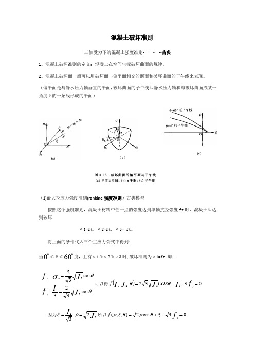
混凝土破坏准则三轴受力下的混凝土强度准则-——-—--古典1。
混凝土破坏准则的定义:混凝土在空间坐标破坏曲面的规律。
2。
混凝土破坏面一般可以用破坏面与偏平面相交的断面和破坏曲面的子午线来表现。
(偏平面是与静水压力轴垂直的平面,破坏曲面的子午线即静水压力轴和与破坏曲面成某一角度θ的一条线形成的平面)(b )(1)最大拉应力强度准则(rankine 强度准则)古典模型按照这个强度准则,混凝土材料中任一点的强度达到单轴抗拉强度ft 时,混凝土即达到破坏.σ1=ft ,σ2=ft, σ3= ft 。
将上面的条件代入三个主应力公式中得到: 当≤θ≤60度,且有σ1≥σ2≥σ3时,破坏准则为σ1=ft.即:θθσcos 323cos 32212JI fJ f t mt=-=-可以得()0332,,1221=-+=fI JJ I tCOS fθθ因为J I212,3==ρξ所以03cos 2),,(=-+=ftf ξθρθξρ在pi 平面上有:0=ξ,所以03cos 2=-ftθρ,故θρcos 23f t =(2)Tresca 强度准则Tresca 提出当混凝土材料中一点应力到达最大剪应力的临界值K 时,混凝土材料即达到极限强度:K =---)21,21,21max(133221σσσσσσ 他的强度准则中的破坏面与静水压力I1ξ的大小没有关系,子午线是与ξ平行的平行线,在偏平面是为一正六边形,破坏面在空间是与静水压力轴平行的正六边形凌柱体。
(3)von Mises 强度理论他提出的理论与三个剪应力都有关取:[]2)(2)(2)(21133221*-+*-+*-σσσσσσ=K 的形式 用应力不变量来表示为:03)(22=-=K f J J注:von 的强度准则的破坏面在偏平面是为圆形,较tresca 强度准则的正六边形在有限元计算中处理棱角较简单,所以其在有限元中应有很广,但其强度与ξ没有关系,拉压破坏强度相等与混凝土的性能不符。
混凝土_多轴强度_破坏准则_本构模型

2.8.1试验设备和方法
所有的混凝土多轴试验装置,按试件的应力状 态分为两大类: 1、常规三轴试验机 一般利用已有的大型材料试验机,配备一个带 活塞的高压油缸和独立的油泵、油路系统。 试验时将试件置于油缸内的活塞之下,试件的 横向由油泵施加液压,纵向由试验机通过活塞加 压。试件在加载前外包橡胶薄膜,防止高压油进 入试件裂缝,胀裂试件,降低其强度。
θ =60o
(2)、压子午线的应力条件 则为σ1 = σ2 ≥ σ3 ,线上有单轴 受压(0,0,-fc )和二轴等拉(ftt, ftt, 0),在偏平面上的夹角θ =60o。
(3)、拉、压子午线与静水 压力轴同交于一点,即三轴等 拉(fttt, fttt, fttt)。拉、压子午线 至静水压力轴的垂直距离即为 偏应力 rt 和 rc。
——国内外对多轴性能的研究概述
计算机的发展应用,有限元分析方法渐趋成熟,为准 确地分析复杂结构提供了强有力的理论和运算手段,研 究合理、准确的混凝土破坏准则和本构关系已成为当务 之急。同时,电子量测和控制技术的进步,为建造复杂 的混凝土多轴试验设备和改进量测技术提供了条件。 混凝土的材料性质复杂多变,其多轴强度和变形又随 多轴应力状态的不同而有很大差异。至今还没有,以后 也难以找到一种准确的理论方法,可以从混凝土原材料 的性质、组成和制备工艺等原始条件推算其多轴力学性 能。因而,最现实和合理的办法是创建混凝土多轴试验 设备、制作试件直接进行试验测定。
试验中:试件挤在一角,变形增大时 试件受到不对称应力增大;变形得不到互 相补偿。这种机械设备使得试件中产生 强制应力,实测破坏荷载并不能真实代 表试件的破坏荷载。
二轴(或三轴)分离试验装置:由二(或三)个独 立的互不相连的机架组成,在水平方向的两个机架, 一个用缆绳悬挂起来,另一个放置在滚动轴承上。垂 直机架用平衡重物悬挂起来,能适应试件在水平方向 和垂直方向上受应力而产生的变形。
混凝土_多轴强度_破坏准则_本构模型(优质参考)共66页文档

2、要冒一次险!整个生命就是一场冒险。走得最远的人,常是愿意 去做,并愿意去冒险的人。“稳妥”之船,从未能从岸边走远。-戴尔.卡耐基。
梦 境
3、人生就像一杯没有加糖的咖啡,凝土_多轴强度_破坏准则_本构模型 4、守业的最好办法就是不断的发展。 5、当爱不能完美,我宁愿选择无悔,不管来生多么美丽,我不愿失 去今生对你的记忆,我不求天长地久的美景,我只要生生世世的轮 回里有你。 (优质参考)
44、卓越的人一大优点是:在不利与艰 难的遭遇里百折不饶。——贝多芬
45、自己的饭量自己知道。——苏联
41、学问是异常珍贵的东西,从任何源泉吸 收都不可耻。——阿卜·日·法拉兹
42、只有在人群中间,才能认识自 己。——德国
43、重复别人所说的话,只需要教育; 而要挑战别人所说的话,则需要头脑。—— 玛丽·佩蒂博恩·普尔
钢筋混凝土破坏准则及本构关系
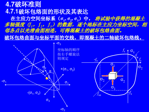
一些常用的、有代表性的混凝土破坏准则列于下表 , 同时给出了原始表达式和统一表达式,可看到两者中 参数的互换关系。
过镇海、王传志、张秀琴等搜集了国内外大量的混 凝士多轴强度试验数据,与按上述准则计算的理论值 进行全面比较,根据三项标准: ①计算值与试验强度的相符程度; ②适用的应力范围宽窄; ③理论破坏包络面几何特征的合理性等加以评定。 所得结论为: 较好的准则:过—王、Ottosen和Podgorski准则; 一般的准则:Hsieh-Ting-Chen,Kotsovos, WillamWarnke准则; 较差准则:Bresler-Pister准则。 在结构的有限元分析中,可根据结构的应力范围和 准确度要求选用合理的混凝土破坏准则。
σ3
转换过 程归纳
ξ
o
3 oct
θ
ξ
静水应力
3 oct
r σ1 =σ2 = σ3 N σ2
σ1
圆柱坐标系及主应 力空间应力分解 σ 1 -σ3 偏斜应力 平面中矢 量的方向 σ2 偏平面 P r θ N σ3 -σ1
-σ3 σ1 -σ2
ξ,r,θ的几何表示 偏平面
压子午线 θ=60o rc rt
3、以混凝土多轴强度试验资料为基础的经验回归式
随试验数据的积累,许多研究人员提出了若干基于试验结果、 较为准确、但数学形式复杂的混凝土破坏准则。准则中一般需 要包含4~5个参数。
这些破坏准则的原始表达式中采用了不同的应力量作 为变量,分5种: ①主应力—fl , f2, f3 ; ②应力不变量—Il ,J2,J3 ; ③静水压力和偏应力—ξ , r,θ; ④八面体应力— σoct ,τoct ; ⑤平均应力—σm ,τm θ。 采用上述应力量致使准则的数学形式差别很大,不 便作深入对比分析。但这些应力量借助下列基本公式 可以很方便地互相变换:
- 1、下载文档前请自行甄别文档内容的完整性,平台不提供额外的编辑、内容补充、找答案等附加服务。
- 2、"仅部分预览"的文档,不可在线预览部分如存在完整性等问题,可反馈申请退款(可完整预览的文档不适用该条件!)。
- 3、如文档侵犯您的权益,请联系客服反馈,我们会尽快为您处理(人工客服工作时间:9:00-18:30)。
混凝土破坏准则三轴受力下的混凝土强度准则-------古典1.混凝土破坏准则的定义:混凝土在空间坐标破坏曲面的规律。
2.混凝土破坏面一般可以用破坏面与偏平面相交的断面和破坏曲面的子午线来表现。
(偏平面是与静水压力轴垂直的平面,破坏曲面的子午线即静水压力轴和与破坏曲面成某一角度θ的一条线形成的平面)(b)(1)最大拉应力强度准则(rankine 强度准则)古典模型按照这个强度准则,混凝土材料中任一点的强度达到单轴抗拉强度ft 时,混凝土即达到破坏。
σ1=ft ,σ2=ft, σ3= ft.将上面的条件代入三个主应力公式中得到: 当≤θ≤600度,且有σ1≥σ2≥σ3时,破坏准则为σ1=ft.即:θθσcos 323cos 32212JI fJ ft m t=-=-可以得()0332,,1221=-+=fI JJ I tCOS fθθ因为J I212,3==ρξ所以03cos 2),,(=-+=ftf ξθρθξρ在pi 平面上有:0=ξ,所以03cos 2=-ftθρ,故θρcos 23f t=(2)Tresca 强度准则Tresca 提出当混凝土材料中一点应力到达最大剪应力的临界值K 时,混凝土材料即达到极限强度:K =---)21,21,21max(133221σσσσσσ 他的强度准则中的破坏面与静水压力I1ξ的大小没有关系,子午线是与ξ平行的平行线,在偏平面是为一正六边形,破坏面在空间是与静水压力轴平行的正六边形凌柱体。
(3)von Mises 强度理论他提出的理论与三个剪应力都有关 取:[]2)(2)(2)(21133221*-+*-+*-σσσσσσ=K 的形式 用应力不变量来表示为:03)(22=-=K f J J注:von 的强度准则的破坏面在偏平面是为圆形,较tresca 强度准则的正六边形在有限元计算中处理棱角较简单,所以其在有限元中应有很广,但其强度与ξ没有关系,拉压破坏强度相等与混凝土的性能不符。
莫尔-库仑强度理论他的理论考虑了材料的抗拉,抗压强度的不同。
适用于脆性材料。
其破坏条件的表达式为:ϕστtan -=c c 为内聚力,ϕ为内摩擦角。
取破坏包络线为直线,当莫尔圆与破坏线相切时,则在这个条件下可以表示成:ϕϕσσσσsin 2cot 23131⎪⎪⎭⎫ ⎝⎛++•=-c 将主应力的计算公式代入并整理的下面两个公式: (1)0cos sin )3cos(3)3sin(sin 31),,(22121=-+++==ϕϕθθϕθc pipi f JJ I J I (2)0cos 6sin )3cos()3sin(3sin 2),,(=-++++=ϕϕθρθρϕξθρξc pi pi f 。
莫尔-库仑破坏曲面为非正六边形锥体,他的子午线为直线,其中ϕϕϕϕϕϕsin 3sin 22tan sin 3sin 22tan -=+=ct在pi 平面上为非正六边形,当00,0==θξ时,ϕϕϕϕϕϕθξϕϕϕϕρρρρsin 3sin 3sin 3)sin 1(6sin 3cos 620sin 3)sin 1(6sin 3cos 62co 0060+-=--=-===+-=+=coco cct f f c c 时,当 当03=σ,平面的双轴强度包络线为一不规则六边形。
当假定拉压相等,0=ϕ时,则莫尔-库仑强度准则相当于tresca 强度准则。
当有拉力时,为了更好的取的近似,可将莫尔-库仑准则与最大拉应力或拉应变强度准则结合起来。
这样做实际是一个三参数强度准则,用ft,c ,和ϕ参数来确定。
Drucker-Prager 强度准则因为六边形角隅部分用于计算机计算太复杂,所以他修改了莫尔-库仑不规则的六边形变成圆形,子午线为直线,并改进了von 准则中与静水压力无关的缺点。
Drucker-Pragre 强度准则的表达式:0),(2121=-+=k f JI J I α或者026),(=-+=k f ραξρξ。
其中k ,α正是常数Druck-prager 强度准则的破坏曲面为圆锥体,圆锥体的大小通过k ,α这两个参数来调整。
三轴受力下的混凝土强度准则--------多参数强度准则(1)由国内外的实验得出混凝土破坏曲线具有以下的特点:1 , 三向应力下,混凝土破坏面与三个方向应力都有关系的函数,在三向条件下,随着压力强度的增加,混凝土的强度也提高。
2 ,破坏面是一个等压轴方向开口的曲线,这个曲面是凸曲面,偏平面上的截面的外形曲线还是子午面上的截线都是光滑的凸曲线。
3 ,在θ为常数的子午面的截线是曲线,不是直线;在ξ为常数的偏平面是的外形曲线是非圆曲线,都随着ξ的变大越来越接近圆形。
《1》三参数破坏准则代表性的破坏准则有Bresler -Pister 破坏准则,Willam -Warnke 破坏准则和黄克智-张远高破坏准则。
三参数公式可由三个强度试验数据来确定,一般是ff f bctt,,其中fbc是材料双轴等压强度。
Bresler -Pister 破坏准则B resler -Pister 建议的强度准则模型中子午线为抛物线,都在偏平面上与θ无关,为圆形。
公式为:)(2f f fcoct c b a coct coct σστ+-= 公式中,系数a,b.c 可根据单轴拉应力,压应力和双轴等压强度实验数据得到。
B resler -Pister 强度准则的子午线为静水压力轴闭口的抛物线,在高静水压力的条件下,拉压子午线可以与静水压力轴相交,这个是违背实验结果的。
Willam -Warnke 破坏准则Willam -Warnke 建议的三参数强度准则特点是在偏平面上形成三轴对称凸面光滑曲边三角形,当ρρct=时,偏平面成圆形,都是子午线还是直线。
公式为:01)(11),,(''=-+=f f ccr f mm m m τστσθρθ或者)11)((''f f cr cmm στθρ-= 其中r 是待定的参数。
[])()()(151132322212).,(3121321σσσσσστσσσσ-+-+-==mm参数ρρct,和r 可以用单轴拉压应力,f tf c '和材料双轴等压强度fbc确定。
当ρρρ0==tc时模型变成两参数的r ,ρ类似Drucker-Pragre 的形式。
当,∞→r 1'==f ffcbc bc,模型变成von Mises 的形式。
黄克智-张远高破坏准则黄克智-张远高的三参数破坏准则既满足混凝土破坏面在子午线上的投影为曲线和在偏平面上投影非圆的特点,并且在pi 平面上面的投影随着ξ的变大越来越接近圆形,是三参数模型中比较好的一个破坏准则。
表达式: 1cos 5.1=++ξθρρc b a其中的参数也是由三组实验数据得到。
四参数混凝土破坏准则四参数混凝土破坏准则典型的有Ottosen 强度模型,Reimann 强度准则,Hsich -Ting -Chen 四参数强度准则和清华大学的强度准则.Ottosen 强度模型是以三角函数为基础的强度准则模型。
这个模型的子午线是曲线,偏平面根据不同静水压力从光滑凸面三角形渐渐变化到圆形。
四参数混凝土破坏准则包括所以应力不变量JI 21,和θ3cos 。
表达式为:)3(cos 01''')3,,(122221 θλλλθ==-++=fI fJf J J I ccbcaCOS f常数a,b 用于确定子午线曲线,λ用于确定偏平面破坏平面。
Ottosen 强度模型是由两个混凝土单轴强度,两个典型的双轴和三轴强度来确定的,其比较全面反映混凝土破坏特征。
Reimann 强度准则的受压子午线为c c b c c a c ff f c+⎪⎪⎪⎭⎫ ⎝⎛+=⎪⎪⎭⎫ ⎝⎛'2''ρρξ其他的子午线采用与ρc有关的方程。
为ρθϕρc)(=。
Reimann 模型改进了莫尔-库仑强度准则,拉压子午线为曲线,且偏平面在ρt处为光滑曲线。
清华大学江见鲸提出来的强度准则为01)cos (2122=-+++fI fJ f Jcccdc b aθ确定参数的和前面一个样子。
与Ottosen 强度模型相比,其结果非常接近,并且参数的标定更容易。
其缺点是在60=θ时候偏平面有点尖,但是在实际的使用中没有太大的区别。
五参数混凝土破坏准则目前有willam -warnke 五参数强度模型和kotsovos 强度模型,我国清华大学的江见鲸他们提出的几个五参数强度模型。
willam -warnke 考虑到三参数模型子午线为直线的缺点,提出啦更普遍的拉,压子午线表达式,为60)(0)(022'1''mc 022'1''mt ,')(5,')(5=+===+==++θθσσρτσσρτf b f b b f f f a f a a f f cm ccccm cccmcm t由于拉压子午线交于静水压力坐标轴上,因此只要五个参数来确定。
偏平面仍然采用三参数模型的椭圆曲线。
但是这种模型子午线向负静水压力轴展开,但当高静水压力下,子午线可能与静水压力轴相交,这个是不符合一般的实验结果的,因此他规定121t ≤≤ρρc时即为限制拉,压子午线适合范围内的子午线便不可能与静水压力轴相交的不合理现象。
所以选用的强度条件和静水压力强度适应范围应该注意。
kotsovos 提出来五参数强度准则(指数型子午线和椭圆组合偏平面的五参数强度准则)拟补willam -warnke 的缺点。