Eaton Hybrid General Introduction-JH
Eaton 电源技术参考手册说明书

High Alert mode
No break Typically 2 ms ± 10% of nominal voltage, default ± 4 Hz, default UPS locks into double-conversion mode when three power line disturbances have forced the unit to double-conversion three times (user adjustable) within a one-hour period (user
406 kg
600 x 1100 x 2020 mm 437 kg
Rear to (default) & rear bottom (optional) IP20
Black; RAL 9005 <10 minutes
468 kg
ENVIRONMENTAL Acoustic Noise: 1m, 25°C ambient temperature
< 1° with static balanced load 1 Hz/s
Page 2 of 4
EATON 93PR 75KW FRAME TECHNICAL SPECIFICATION
Model (Part Number):
93PR25(75)-MBS / MBSINTBAT
93PR50(75)-MBS / MBSINTBAT
Back feed protection
40 A 38 A 37 A 45 A
220/380 V; 230/400 V; 240/415 V 187 to 276 V
rated voltage -15% / +10% 50 or 60 Hz, user configurable
Eaton 自由系列电磁开关和电机拨码器说明说明书
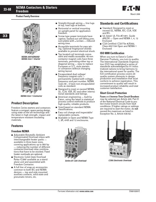
March 2009Product Family OverviewProduct DescriptionFreedom Series starters and contactors feature a compact, space-saving design, using state-of-the-art technology and the latest in high strength, impact and temperature resistant insulating materials.FeaturesFreedom NEMA■Adjustable Bimetallic AmbientCompensated Overload relays with interchangeable heater packs — available in three basic sizes,covering applications up to 900 hp — reducing the number of different contactor/overload relay combina-tions that have to be stocked. Fixed heater overloads are optional.■Electronic Solid-State Overload Relay (C396) available as a stand-alone unit and assembled with Freedom Contactor.■ A full line of snap-on accessories common to both IEC and NEMA devices — top and side mounted auxiliary contacts, solid-state and pneumatic timers, etc.■Straight-through wiring — line lugs at top, load lugs at bottom.■Horizontal or vertical mounting on upright panel for application freedom.■Screw type power terminals have captive, backed-out self-lifting pres-sure plates with ± screws — reduced wiring time.■Accessible terminals for easy wir-ing. Optional fingerproof shields available to prevent electrical shock.■Top located coil terminals conve-nient and readily accessible. 45 mm contactor magnet coils have three terminals, permitting either top or diagonal wiring — easy to replace European or U.S. style starters or contactors without changing wiring layout.■Encapsulated dual voltage/frequency magnet coils —permanently marked with voltage, frequency and part number. NEMA Sizes 00 – 0 have non-encapsulated coils as standard.■Designed to meet or exceed NEMA, UL, CSA, VDE, BS and other interna-tional standards and listings.■American engineering — built by Eaton, using the latest in statistical process control methods to produce high quality, reliable products.■Sized based on standard NEMA classifications.■Easy coil change and inspectable/replaceable contacts.■Available in Open and NEMA Type 1, 3R, 4/4X and 12 enclosures.Standards and Certifications■Standard: Designed to meet or exceed UL, NEMA, IEC, CSA, VDE and BS.■UL listed: UL File #E1491, Guide #NLDX — Open and NEMA 1, 4, 12 Enclosed■CSA Certified: CSA File #LR353, Class #321104 Open and NEMA 1 EnclosedISO 9000 CertificationWhen you turn to Eaton’s Cutler-Hammer Products, you turn to quality. The International Standards Organiza-tion (ISO) has established a series of standards acknowledged by 91 indus-trialized nations to bring harmony to the international quest for quality. The ISO certification process covers 20 quality system elements in design, production and installation that must conform to achieve registration. This commitment to quality will result in increased product reliability and total customer satisfaction.Short Circuit ProtectionFuses and Inverse-Time Circuit Breakers may be selected per Article 430, Part D of the National Electrical Code to pro-tect motor branch circuits from fault conditions. If higher ratings or settings are required to start the motor, do not exceed the maximum as listed in Exception No. 2, Article 430-52.NEMA AN16DN0AB NEMA Size 1 StarterNEMA Size 1 ContactorSeries B1 32A OverloadC396 Electronic OverloadMarch 2009Starters — 3-Phase Non-reversing and Reversing, Full VoltageContentsDescriptionPageProduct Family OverviewProduct Description. . . . . . 33-68Features . . . . . . . . . . . . . . . 33-68Standards andCertifications . . . . . . . . . . 33-68Catalog NumberSelection . . . . . . . . . . . . . 33-69Starters — 3-Phase Non-reversing and Reversing, Full Voltage, Bi-Metallic OverloadProduct Description. . . . . . 33-73Features . . . . . . . . . . . . . . . 33-73Technical Data . . . . . . . . . . 33-74Wiring Diagrams . . . . . . . . 33-74Product Selection. . . . . . . . 33-75Starters — 3-Phase Multispeed, Bi-Metallic OverloadProduct Selection. . . . . . . . 33-76Starters — Single-PhaseNon-reversing, Full Voltage, Bi-Metallic OverloadProduct Description. . . . . . 33-77Wiring Diagrams . . . . . . . . 33-77Product Selection. . . . . . . . 33-77Starters — 3-Phase Non-reversing and Reversing, Full Voltage,C386 Electronic Overload . . 33-78Technical Data . . . . . . . . . . . . . 33-79Accessories . . . . . . . . . . . . . . . 33-82Auxiliary Contacts . . . . . . . 33-86DC Magnet Coils . . . . . . . . 33-88Mounting Plates. . . . . . . . . 33-89Special Modifications . . . . . . . 33-90Renewal Parts . . . . . . . . . . . . 33-91Dimensions . . . . . . . . . . . . . . . 33-94Product DescriptionNon-reversingThree-phase, full voltage magnetic starters are most commonly used to switch AC motor loads. Starters con-sist of a magnetically actuated switch (contactor) and an overload relay assembled together.ReversingThree-phase, full voltage magnetic starters are used primarily for revers-ing of 3-phase squirrel cage motors. They consist of two contactors and a single overload relay assembledtogether. The contactors are mechani-cally and electrically interlocked to prevent line shorts and energization of both contactors simultaneously.Features■Bimetallic Ambient Compensated Overload relays — available in three basic sizes covering applications up to 900 hp — reducing number of different contactor/overload relay combinations that have to be stocked.These overload relays feature:❑Selectable Manual or Automatic Reset operation.❑Interchangeable heater packs adjustable ±24% to match motor FLA and calibrated for 1.0 and 1.15 service factors. Heater packs for smaller overload relay will mount in larger overload relay — useful in derating applications such as jogging.❑Load lugs built into relay base.❑Single-phase protection, Class 20 or Class 10 trip time.❑Overload trip indication.❑Electrically isolated NO-NC con-tacts (pull RESET button to test).■The C396 is a self-powered, robust electronic overload designed for integrate use with Freedom NEMA contactors.❑Tiered feature set to provide cov-erage specific to your application.❑Broad 5:1 FLA range for maxi-mum flexibility.❑Coverage from 0.05 – 1500 Amps to meet all your needs.■Long life twin break, silver cadmium oxide contacts — provide excellent conductivity and superior resistance to welding and arc erosion. Gener-ously sized for low resistance and cool operation.■Designed to 3,000,000 electrical operations at maximum hp ratings up through 25 hp at 600V.■Steel mounting plate standard on all open type starters.■Wired for separate or common control.Non-reversing■Holding circuit contact(s) supplied as standard:❑Sizes 00 – 3 have a NO auxiliary contact block mounted on right-hand side (on Size 00, contact occupies 4th power pole position — no increase in width).❑Sizes 4 – 5 have a NO contact block mounted on left side.❑Sizes 6 – 7 have a 2NO/2NC contact block on top left.❑Size 8 has a NO/NC contact block on top left back and a NO on top right back.Reversing■Each contactor (Size 00 – 8) supplied with one NO-NC sidemounted contact block as standard. NC contacts are wired as electrical interlocks.NEMA Size 1 — Cat. No. AN16DN0ABNEMA Size 1 — Cat. No. AN56DN0ABMarch 2009Starters — 3-Phase Non-reversing and Reversing, Full VoltageTechnical DataTable 33-96. Wire (75°C) Sizes — AWG or kcmil — NEMA Sizes 00 – 2 — Open and EnclosedᕃTwo compartment box lug.ᕄMinimum per NEC. Maximum wire size: Sizes 00 and 0 to 8 AWG and Sizes 1 – 2 to 2 AWG.Table 33-97. Wire (75°C) Sizes — AWG or kcmil — NEMA Sizes 3 – 8 — Open and EnclosedᕅMinimum per NEC. Maximum wire size: Sizes 00 and 0 to 8 AWG and Sizes 1 – 2 to 2 AWG.Wiring DiagramsFigure 33-24. Typical Wiring Diagrams — Three-Phase and Single-Phase ApplicationsNEMA SizeWire Size ᕄ Cu OnlyPower Terminals — Line0001212 – 16 AWG stranded, 12 – 14 AWG solid 8 – 16 AWG stranded, 10 – 14 AWG solid 8 – 14 AWG stranded or solid3 – 14 AWG (upper) and/or 6 – 14 AWG (lower) stranded or solid ᕃPower Terminals — Load — Cu Only (stranded or solid)00 – 01 – 214 – 6 AWG stranded or solid 14 – 2 AWG stranded or solidControl Terminals — Cu Only12 – 16 AWG stranded, 12 – 14 AWG solidNEMA SizeWire Size ᕅPower Terminals — Line and Load31/0 – 14 AWG Cu/Al4Open — 3/0 – 8 AWG Cu; Enclosed — 250 kcmil — 6 AWG Cu/Al 5678750 kcmil — 2 AWG; or (2) 250 kcmil — 3/0 AWG Cu/Al (2) 750 kcmil — 3/0 AWG Cu/Al (3) 750 kcmil — 3/0 AWG Cu/Al (4) 750 kcmil — 1/0 AWG Cu/AlControl Terminals — Cu Only12 – 16 AWG stranded, 12 – 14 AWG solidTable 33-98. Plugging and Jogging Service Horsepower Ratings ᕆᕆMaximum horsepower where operation is interrupted more than 5 times per minute, or more than 10 times in a 10 minute period. NEMA Standard ICS2-1993 table 2-4-3.Kits and Accessories■Auxiliary Contacts, contactor mounted — Pages 33-86 – 33-87. ■Transient Suppressor, for magnet coil — Pages 33-84.■Timers — Solid-State andPneumatic, mount on contactor — Page 33-83.Renewal Parts Publication Numbers■See Page 33-91.NEMA Size 200V 230V 460V 575V 000123—1-1/237-1/2151/21-1/2310201/22515301/2251530456256012530751506015030060150300March 2009Starters — 3-Phase Non-reversing and Reversing, Full Voltage, Bi-Metallic OverloadProduct SelectionWhen Ordering Supply■Catalog Number■Heater pack number (see selectiontable, Pages 33-107 – 33-108) or full load current.Table 33-99. Type AN16/AN56 NEMA — Manual or Automatic Reset Overload Relay — Non-reversing and ReversingNote: Starter Catalog Numbers do not include heater packs. Select one carton of three heater packs. Heater pack selection, Pages 33-107 – 33-108.ᕃUnderscore (_) indicates coil suffix required, see Table 33-100.ᕄMaximum horsepower rating of starters for 380V 50 Hz applications: ᕅThe service-limit current ratings represent the maximum rms current, in amperes, which the controller shall be permitted to carry for protracted periods in normal service. At service-limit current ratings, temperature rises shall be permitted to exceed those obtained by testing the controller at itscontinuous current rating. The current rating of overload relays or trip current of other motor protective devices used shall not exceed the service-limit current rating of the controller.ᕆCommon control. For separate 120V control, insert letter D in 7th position of listed Catalog Number. EXAMPLE: AN56VN D 0CB.Magnet Coils — AC or DCStarter coils listed in this section also have a 50 Hz rating as shown in the adjacent table. Select required starter by Catalog Number and replace the magnet coil alpha designation in the Catalog Number (_) with the proper Code Suffix from the adjacent table.For Sizes 00 – 2 and 5 – 8, the magnet coil alpha designation will be the next to last digit of the listed Catalog Num-ber. EXAMPLE: For a 380V, 50 Hz coil, change AN16BN0_C to AN16BN0L C. For all other sizes, the magnet coil alpha designation will be the last digit of the listed Catalog Number.For DC Magnet Coils , see Accessories, Pages 33-88 – 33-89.Table 33-100. AC Suffix CodeᕇNEMA Sizes 00 and 0 only.ᕈNEMA Sizes 00 and 0 only. Sizes 1 – 8 are 24/60 only.NEMA Size Continuous Ampere Rating Service-Limit CurrentRating ᕅ(Amperes)Maximum UL Horsepower ᕄ3-PoleNon-reversing ᕃ3-PoleReversing ᕃVerticalReversing ᕃPrice U.S. $1-Phase3-Phase115V 230V 208V 240V 480V 600V CatalogNumber Price U.S. $Catalog Number Catalog Number 009111/311-1/21-1/222AN16AN0_C AN56AN0_C —01821123355AN16BN0_C AN56BN0_C AN56BNV0_12732237-1/27-1/21010AN16DN0_B AN56DN0_B AN56DNV0_2455237-1/210152525AN16GN0_B AN56GN0_B AN56GNV0_390104——25305050AN16KN0_AN56KN0_AN56KNV0_4135156——4050100100AN16NN0_AN56NN0_AN56NNV0_5270311——75100200200AN16SN0_B AN56SN0_B —6540621——150200400400AN16TN0_C AN56TN0_C —7810932——200300600600AN16UN0_B AN56UN0_B —8 ᕆ12151400——400450900900AN16VN0_BAN56VN0_B—NEMA Size 00012345678Horsepower1-1/2510255075150300600900Size 0Non-reversing StarterSize 1Reversing StarterSize 3 Vertical Reversing StarterNEMA Size 0Cat. No. AN56BN0ACCoil Volts and Hertz Code Suffix 120/60 or 110/50240/60 or 220/50480/60 or 440/50600/60 or 550/50A B C D 208/60277/60208 – 240/60 ᕇ240/50E H J K 380 – 415/50550/5024/60, 24/50 ᕈ24/50L N T U 32/5048/6048/50V W YTechnical Data. . . . . . . . . . Pages 33-79 – 33-81Overload Relay . . . . . . . . . Page 33-103Dimensions . . . . . . . . . . . . Pages 33-96 – 33-98Special Modifications . . . Page 33-90Accessories. . . . . . . . . . . . Pages 33-82 – 33-90March 2009Starters — Single-Phase Non-reversing, Full Voltage, Bi-Metallic OverloadProduct DescriptionSingle-phase, full voltage magnetic starters connect the motor directly across the line, allowing it to draw full inrush current during start-up. These starters are most commonly used for control of self-starting single-phase motors up to 15 horsepower at 230V. They consist of a 2-pole electromag-netic contactor to make and break the motor power circuit and an overload relay to provide running overload protec-tion. Starters listed in the table include:■Two-pole Freedom Series contactor with long life twin break, silver cadmium oxide contacts. Generously sized for low resistance and cool operation. Designed to 3 mil-lion electrical operations at maximum hp and 30 million mechanical operations to Size 0, 10 million operations to Size 2 and 6 million operations to Size 3.■Three-pole Freedom Series overload with poles 2 and 3 wired in series for motor overload protection. This over-load is ambient compensated, selectable Manual or Auto-matic reset, interchangeable Class 10 or 20 heater packs, 1.0 or 1.15 service factor selectability, overload trip indica-tion and electrically isolated NO-NC contacts (pull RESET button to test).■Holding circuit NO auxiliary contact supplied as standard. On Size 00, the contact occupies the 4th power pole position. Sizes 0 – 3 have the NO auxiliary mounted on the right side of the contactor.■Steel mounting plate as standard on all open type starters. Wired for separate or common control.Wiring DiagramsFigure 33-25. Typical Wiring Diagrams — Single-Phase Applications (Factory Wired)Product SelectionWhen Ordering Specify■Catalog Number■Heater Pack Number (see selection table, Pages 33-107 – 33-108) or full load current.Table 33-104. Type BN16 NEMA — Manual or Automatic Reset Overload RelayNote: Starter Catalog Numbers do not include heater packs. Select 1 carton of 3 heater packs. Heater pack selection, Pages 33-107 – 33-108.ᕃFor separate 120V control circuit. For maximum hp at listed motor voltages, use the rating of other starters of same size.NEMA Size 1 — Cat. No. BN16DN0ABNEMA SizeMaximum Horsepower MagnetCoil Voltage (60 Hz)Open Type 2-Pole Motor Voltage 1-Phase Catalog Number Price U.S. $001152301/31120 ᕃ240BN16AN0AC BN16AN0BC 011523012120 ᕃ240BN16BN0AC BN16BN0BC 111523023120 ᕃ240BN16DN0AB BN16DN0BB 1P 11523035120 ᕃ240BN16PN0AB BN16PN0BB 211523037-1/2120 ᕃ240BN16GN0AB BN16GN0BB 31152307-1/215120 ᕃ240BN16KN0A BN16KN0BContentsDescriptionPage Thermal Overload RelaysProduct Description. . . . . . 33-103Features . . . . . . . . . . . . . . . 33-103Operation . . . . . . . . . . . . . . 33-103Technical Information . . . . 33-103Technical Data . . . . . . . . . . 33-104Factory Modifications . . . . 33-105Accessories. . . . . . . . . . . . . 33-105Replacement Parts. . . . . . . 33-105Dimensions. . . . . . . . . . . . . 33-106Product Selection. . . . . . . . 33-107Heater Pack Selection . . . .33-107Product DescriptionC306 Overload Relays are designed for use with CE or CN non-reversing and reversing contactors. Four sizes are available for overload protection up to 144A.Features■Selectable Manual or Automatic Reset operation.■Interchangeable Heater Packs adjustable ±24% to match motor FLA and calibrated for use with 1.0 and 1.15 service factor motors.Heater packs for 32A overload relay will mount in 75A overload relay — useful in derating applications such as jogging.■Class 10 or 20 heater packs.■Load lugs built into relay base.■Bimetallic, ambient compensated operated. Trip free mechanism.■Electrically isolated NO-NC contacts (pull RESET button to test).(Electrical Ratings see Table 33-158 on Page 33-104).■Shrouded or fingerproof terminals to reduce possibility of electrical shock.■Meets UL 508 single-phasing requirements.■UL listed, CSA certified, NEMA compliance and CE mark.OperationC306 Overload Relay SettingFigure 33-43. FLA Dial AdjustmentFor motors having a 1.15 service fac-tor, rotate the FLA adjustment dial to correspond to the motor’s FLA rating. Estimate the dial position when the motor FLA falls between two letter values as shown in the example.For motors having a 1.0 service factor, rotate the FLA dial one-half position counterclockwise (CCW).Figure 33-44. Manual/Automatic Reset The overload relay is factory set at M for manual reset operation. For auto-matic reset operation, turn the reset adjustment dial to the A position as shown in the illustration.Automatic reset is not intended for two-wire control devices.Test for Trip IndicationTo test overload relay for trip indica-tion when in manual reset, pull out the blue reset button. An orange flag will appear indicating that the device has tripped. Push reset button in to reset.Warning — To provide continued pro-tection against fire or shock hazard, the complete overload relay must be replaced if burnout of the heater element occurs.Technical InformationGeneral“Overload relays are provided to pro-tect motors, motor control apparatus and motor-branch circuit conductors against excessive heating due to motor overloads and failure to start. This definition does not include:1) motor circuits over 600V,2) short circuits,3) ground faults and 4) fire pump control.” (NEC Art. 430-31)Time Current CharacteristicsThe time-current characteristics of an overload relay is an expression of per-formance which defines its operating time at various multiples of its current setting. Tests are run at Underwriters Laboratories (UL) in accordance with NEMA Standards and the NEC. UL requires:■When tested at 100 percent of its current rating, the overload relay shall trip ultimately.■When tested at 200 percent of its current rating, the overload relay shall trip in not more than 8 minutes.■When tested at 600 percent of the current rating, the overload relay shall trip in not more than 10 or 20 seconds, depending on the Class of the relay.“Current Rating” is defined as the minimum current at which the relay will trip. Per NEC, an overload must ultimately trip at 125% of FLA current (heater) setting for a 1.15 service factor motor and 115% FLA for a 1.0 service factor motor.“Current Setting” is defined as the FLA (Full Load Amperes) of the motor and thus the overload heater pack setting.Example: 600% of current rating is defined as 750% (600 x 1.25) of FLA current (heater) setting for a 1.15 ser-vice factor motor. A 10A heater setting must trip in 20 seconds or less at 75A 32A OverloadCat. No. C306DN3BProduct SelectionTable 33-166. C306 Thermal Overload RelaysᕃNEMA Sizes 5 – 8 use the 32A overload in conjunction with CTs.ᕄSeries B overload relays have load lugs built into relay base and will only accept Series B heater packs. These relays can be directly attached to contactor or they can be DIN rail or panel mounted using adapter on Page 33-105.ᕅThese relays can be panel mounted only.Table 33-167. C306 Thermal Overload RelaysᕆOverload relay assembled with mounting adapter for DIN rail or panel mount.ᕇPanel mount only.ᕈNEMA Sizes 5 – 8 use the 32A overload in conjunction with CTs.Heater Pack SelectionHeater packs H2001B to H2017B and H2101B to H2117B are to be used only with Series B overload relays Catalog Numbers C306DN3B (Part No. 10-7016) and C306GN3B (Part No. 10-7020). The load lugs are built into the overload relay base to allow load wiring prior to heater pack installa-tion. The previous heater design had integral load lugs. The Series B heater packs are electrically equivalent to the previous heater design. Heaters H2018-3 to H2024-3 have not changed.Table 33-168. Starters with Series B Overload RelaysNote: The series of a starter is the last digit of the listed Catalog Number. EXAMPLE: AN16DN0A B .For Use with Freedom Series Contactors Maximum Ampere RatingNumber of PolesOpen Type NEMA 1 Enclosed NEMA Size Catalog NumberPrice U.S. $Catalog Number Price U.S. $00, 01, 2345 – 8 ᕃ32 ᕄ75 ᕄ105 ᕅ144 ᕅ—3333—C306DN3B C306GN3B C306KN3C306NN3—C306DG3B C306GG3B —75A OverloadCat. No. C306GN3B 75A OverloadCat. No. C306GT3B 32A OverloadCat. No. C306DT3B 32A OverloadCat. No. C306DN3BFor Stand-Alone Applications Maximum Ampere RatingNumber of PolesOpen Type NEMA Size Catalog NumberPrice U.S. $00, 0, 1 ᕆ1 ᕆ3 ᕇ4 ᕇ5 – 8 ᕈ3275105144—3333—C306DT3B C306GT3B C306KN3C306NN3—Heater PackH2001B – H2017BHeater PackH2101B – H2117BHeater Pack H2018 – H2024NEMA — AN Type IEC — AE Type Size Series Size Series 00 – 01 – 2567 – 8C B B C BA – F G – KC BTechnical Data . . . . . . . . Page 33-104Dimensions. . . . . . . . . . . . Page 33-106。
Eaton 电源分发板产品介绍说明书

Distribution switchboardsThe broadest offering in the industryIndustry-leading Eaton switchboardsEaton’s electrical group offers the widest selection of switch-board types in the industry, and this is only the start.Our switchboards are built from the ground up based on customer input and needs. From the simplest 800A switchboard to Web-enabled, Eaton switchboards offer flexibility in designs to accommodate any power distribution need you have.Our flexible designs are onlyas good as the people andservice that bring the productsto you. Eaton has uniquelypositioned manufacturingcenters of excellencethroughout the United States.Our 18 facilities, strategicallylocated near our customers,provide more than just switch-boards and panelboards. Theyare your personal plants. TheseRegional Manufacturing Facilitieshave the capability of muchlarger facilities. They understandyour needs and your markets...because they are right there.Our goal, and the goal of ouroutstanding sales team, is toexceed your expectations.From emergency shipments tolarge projects, from new con-struction to aftermarket and ren-ovation, we have the experienceand expertise to help you.As you review the productsin this brochure, rememberthat this is only a samplingof our capabilities. To learn more,we invite you to contact yourlocal sales office or plant, andto come visit us.178429365Pow-R-Line C switchboardsEaton’s distributionswitchboards combine a space-saving design with modular construction and increased systems ratings to provide economical anddependable electrical system distribution and protection.Features•6000A maximum main bus rating • 600 Vac and below • Front or rear accessible • Indoor or outdoor enclosures •ANSI-61 gray powder coat paint finish•Microprocessor-based metering, monitoring and communication devices • Utility metering provisions •Surge protective devices (SPD)• Ground fault protection •Busway and transformer connections• Integrated panelboards (IFS E )•65 kAIC standard bus bracing; optional 100 or 200 kAIC •Aluminum or optional copper bus•Meets NEMA Standard PB-2 and UL 891•Seismically qualifiedMain devices•Magnum E DS power circuit breakers, 800–5000A • Molded-case circuit breakers, 400–2500A, fixed mounted •Pringle bolted pressure contact switches, 800–5000A •Fusible switches, 400–1200A1. Utility MeteringCompartmentsAvailable to meet standard or specific requirements. Units can be arranged for hot or cold sequence.2. Single Chassis DesignProvides device flexibility, accommodating both circuit breaker and fusible switches.3. Pow-R-Line C SwitchboardsGroup-mounted distribution switchboards.6. Electronic T rip Unit SystemAdvanced technology options offer superior protection, energy management and communications.7. Surge Protective DeviceIntegrally mounted with overcurrent feeder.Electronic trip unit systemEaton electronic trip units provide enhanced accuracy and reliability for protection and optimum system coordination.Surge protective devicesEaton’s surge protectivedevices (SPDs) protect sensitive electronic equipment from the damaging effects of high and low energy transients, as well as high-frequency noise.The SPD, combined with our innovative connection, yields the industry’s lowest let-through voltage.Wide range of surge ratings Surge current ratings from 100 to 400 kA per phaseprovide a range of cost-effective facility-wide protection solutions. Products are third-party tested to verify published surge current ratings.SPD mounted within the enclosure eliminates extra wiring and the need for outboard wall space:•UL 1449 Listed high-performance suppression system and parallel hybrid filter technology • Diagnostic system •Integral circuit breaker disconnect4. Eaton Molded-CaseCircuit Breakers 225A, electronic tripframe (left); 600A, electronic trip frame (middle); and 2500A, electronic trip frame (right).5. Magnum DS PowerCircuit Breakers8. Metering and MonitoringDevicesPower Xpert Gateway (front) and IQ 250 Meter (back).9. Eaton’s Power XpertCommunications System, Programming and Monitoring Accomplished remotely from a personal computer via the Web.Group-mounted distribution devices•Molded-case circuit breakers, 15–2000A•Fusible switches, 30–1200AMetering andmonitoring devicesA wide range of metering options for power measurement and power quality is available. Along with local display, these meters can provide Web-enabledmonitoring of Eaton switchboards and other equipment via an open communications architecture. The Power Xpert Gateway enables third-party equipment to communicate across this same system.DistributionswitchboardsIQ Energy SentinelsPower and energy information from IQ Sentinels can be communicated to a PC, a panel-mounted central energy display (CED), or even existing building management or distribution control systems.IQ Energy SentinelsCost-effectivesubmetering throughout the electrical systemThese devices monitor power and energy readings down to the smaller loads. They measure watts, peak demand andwatt-hours within a one-percent accuracy level.The device mounts directly on F-, J- or K-Frame feeder breakers without requiring additional panel height. A universal sentinel is available where breaker mounting is not feasible and for the larger frame breakers.162345Pow-R-Line i switchboardsPow-R-Line i distributionswitchboards are engineered in a compartmentalized design for applications where a greater degree of component isolation is required. A wide variety of configurations is possible, including utility metering, customer metering, main devices, branch devices, accessories and enclosures.Significant safety features•Individual compartments for branch devices help eliminate possible contact with the main bus and reduce fault propagation•Three-section construction with each barriered from the other:•Device section —each device is mounted in its own compartment•Busbar section —contains both horizontal and vertical busses•Rear cable compartment — completely isolated from the busbars•Insulated runbacks, so that power is taken from the protective device by the runback through a full-height glass-polyester barrier to the rear cable compartment, virtually eliminating the possibility of accidental contact with the main busses during installation or maintenanceConstruction features•Full family of metering and protective devices available •Custom-built utility metering compartments •Individually mounted main devices•Compartmentalized feeder devices•Meets NEMA Standard PB-2 and UL 891• Rear accessible•65 kAIC standard bus bracing; optional 100 and 200 kAIC •Aluminum or optional copper busbar •ANSI-61 gray powder coat paint finish •Indoor and outdoor enclosures•Seismically qualifiedA wide selection of branch devices Circuit breakersBranch circuit breakers range from 150A to 1200A Fusible switchesBranch fusible switches are avail-able from 100A to 1200A frames1. Branch Circuit BreakersShown in single- and tandem- mounted construction.2. Fusible SwitchesBranch fusible switches in single-unit construction.5. Laser Cut andPower Coat FinishLaser cut panelboard trims with a high-quality baked-on powder coat finish provides a high-quality appearance.6. Benefits of IFSIFS can be integrated with service equipment wherepanelboards are needed in the electrical distribution equipment room. IFS lowers installation time and saves space.Integrated facility systems (IFS)Eaton is the industry leader in integrated switchboards with more than 100,000 IFS sections delivered to customers. Eaton’s Integrated Facility Systems E (IFS) switchboards can reduce the overall space requirement over traditional panelboard and transformer installations. Because IFS is factory assembled and wired between major components, there are fewer pieces to handle and install, thus reducing installation time.IFS is ideal for both new construction and renovation. Each IFS switchboard is custom designed to meet customer requirements. Specificrequirements for panelboard configurations, as well as transformers and otherequipment, can be customized into IFS switchboards. Eaton’s experience andcapabilities ensure that your IFS is configured to yourexacting standards and delivered on time from one of Eaton’s 18 assembly plants.Standard panelboard andtransformer configurations can ship in as few as two weeks. These include IFS sections with 480Y/277 Vac lighting panelboards with a feeder to a NEMA TP1 transformerfeeding one or more 208Y/120 Vac panelboard(s). All breakers are installed to your drawings and factory wired between the transformer feeder device and the 208 Vac lighting panelboard.3. Pow-R-Line i SwitchboardsCompartmentalized design for increased device isolation.4. Barriered ConstructionOvercurrent devices isolated from bus.Features• Single - and three-phase • 600 Vac maximum• Integrated lighting panelboards • Integrated power panels • Lighting control •Dry-type distribution transformers• Breakers and fusible devices •Provisions for customer- installed equipmentIFS Space-Saving CapabilitiesAn IFS switchboard can significantly reduce the size of an electrical room. Replacing traditional panelboards and transformers with IFS can free up valuable space for the owner. Ideal for facility electrical upgrades where space is limited.Factory Installed WiringTransformers are pre-wired in Eaton’s assembly facility from the primary side feeder (when in the same switchboard) to the secondary overcurrent device. All wiring is marked “Factory Installed” using industry convention colored wire markings. All factory cabling is in accordance with the National Electrical Code using the same standards as field wiring.• Special heights and depths • Metering•UL 891 Listed and meets NEMA PB-2 standards • Seismically qualified • Designs for raised floors •Indoor and outdoor enclosures•Automatic transfer switches1523467Commercial metering switchboardsEaton offers a number of options for commercialmetering switchboards. These include assemblies that meet utility requirements for bulb type watt-hour meters and electronic tenant metering switchboards.Features•Free-standing switchboard construction•Factory-assembled complete with interconnections from incoming mains to the meter and to the tenant main •UL 891 Listed and meets NEC and NEMA PB-1 standards • Seismically qualified •Indoor and outdoor enclosuresUtility type watt-hour meter switchboards•Available with different meter socket configurations:•EUSERC- approved designs through 200A•Lever bypass meter sockets through 400A•Choice of fusible or circuit breaker tenant mains •Hot or cold sequences metering provisionsElectronic tenant metering•Ideal for third-party metering of tenants •Capabilities to read meters remotely• Revenue-grade accuracy •Monitor tenants and loads from 30A through 400A1. WWCMS ConstructionAssembly includes meter socket and test block perEUSERC requirements, pre-wired to tenant disconnect.2. WCMS ConstructionTypical 200A seven-jaw sockets with manual lever bypass connected to circuit breaker disconnects in hot sequence arrangement.3. IQ Multipoint EnergySubmeter II T enant Mains and Sensors5. IQ Multipoint EnergySubmeter II T enant Metering Switchboard 6. Eaton’s Electronic T enantMetering with QuadlogicMeters87. Quadlogic with IntegratedCommunications, Load Profiling, Time-of-Use Data 8. Pow-R-Line C InstantSwitchboardsPreassembled and available from stock.9. Seismic QualificationPow-R-Line Cinstant switchboardsInstant switchboards include EUSERC utility metering provisions and a fused main switch with optional distribution panelboard.Construction features•Completely enclosed with front, rear and side covers •Manufactured of code-gauge steel with ANSI-61 gray powder coat paint finish •Indoor and outdoor enclosures•Outdoor units include front hinged padlockable door •UL Listed and meets EUSERC, NEC and NEMA standards •Seismically qualifiedService ratings•120/240 Vac(singe-phase, three-wire)• 208Y/120 or 240/120 Vac (three-phase, four-wire)• 480Y/277 Vac(three-phase, four-wire)Metering compartment• Meets EUSERC standards •Barriered hot sequence CT provisions•Provisions for meter socket with test block provision •Hinged sealable compartment doors•Standard section includes two 15-inch-high doors (one for socket, one blank)Main switch•400A, 600A or 800A main overcurrent devices •Load lugs or connection to panelboard•Hinged cover with interlockDistribution panelboard• Factory installed •Provisions for bolt-on circuit breakersEaton switchboards Quality construction Parts are manufactured to exacting specifications to ensure precision construction of stable, rigid structuresSeismic qualificationEaton switchboards are seismically tested and qualified to exceed requirements of theUniform Building Code (UBC), the California BuildingCode (CBC) and the International Building Code (IBC)Quality assuranceFinal testing helps ensure that each switchboard performs in accordance with UL standards and customer specificationsAll switchboards are backed by Eaton’s commitment to quality, safety and reliability.4. T ype WCMS (left) and T ypeWWCMS (right)Reliable multiple circuit distribution and metering for commercial applications.•Choice of two metering solutions:•Eaton IQ Multipoint Energy Submeter II •Quadlogic•Software and communications packages•Secured remote access14365171. Receptacles Sub-AssemblyReceptacles are color-codedfor Phase A, B and C, neutraland ground.Roll-up generatorQuick ConnectswitchboardProduct descriptionThe Eaton generator QuickConnect switchboard is anengineered assembly designedto allow safe and fast connectionof a mobile generator to yourfacility’s electrical system or aportable load bank.Through inclusion of cam-typereceptacles, standard mechanicallugs, dedicated generator-servicedisconnect and a manual key-interlock transfer scheme, youcan quickly and safely supplybackup power to parts of yourelectrical power system that arenot currently covered by yourpower system, or you can backup existing generators.Loads connected to thegenerator quick connectswitchboard can immediatelybe safely transitioned to analternative power source,made possible by the generatorquick-connect switchboard.Specifications• UL 891 Listed switchboard• 480 Vac and below• Sizes 400A–4000A• Indoor and outdoorenclosures• Key interlocked mainovercurrent devices• Quick-connects to speedand simplify generatorconnections2. Generator Quick ConnectSwitchboard2000A Quick Connectswitchboard with key interlockedmain and generator connections.3. Customized, Design-Buildand Retrofit Solutions4. Panelboards and EnclosedBreakers Up to 1200A5. Switchboards Up to 6000A6. Emergency Quick Shipand Pickup7. Satellite PlantsBenefits of the generatorQuick Connect switchboardSpeed of connectionThe owner does not haveto do any of the following thatare common roll-up generatorpower situations:• No making additional fieldmodifications to an internalswitchboard in order toconnect the generator cablesafter the initial installation• No modifying the building’sphysical structure toaccommodate generatorcables (e.g., drilling holesin walls)• No running cables throughdoorways or windows andthrough hallways or up stairsSafer and more reliableReduction of the potentialfor safety problems associatedwith connecting the mobilegenerator to the facility’selectrical system underlost-power conditions• A permanent connectionpoint for mobile power, nota temporary connection• Installed under normalcircumstances, not duringa possibly chaotic lostpower situation• Tested as part of theinstallation, providingassurance when needed• Eliminates the safetyhazards of generator cablesrun through doorways andup stairways; building doorsand/or windows remainclosed for security andsafety reasonsAs part of the larger assembly,there are several sub-assembliesthat provide greater function andbenefit to facilities• Generator ServiceDisconnect—A UL Listed circuit breakerinterlocked with the servicedisconnect. The generatordisconnect can be rated upto 4000A continuous andmay include ground faultSatellite manufacturingfacilitiesBest service in the industryEaton’s switchboards are custom-built to your requirements usingworld-class manufacturingtechniques. Eaton is the onlyelectrical manufacturer that notonly uses huge manufacturingplants to meet the needs ofour customers, but also has16 smaller Satellite BusinessCenters across the countryto cater to your individualneeds. We’re probably rightin your backyard!protection, shunt trips, alarms,single-phase protection andauxiliary contacts. Such optionscan allow for integration intoa larger control system toaccomplish load sheddingwhile the facility is underbackup power• Cam-Type ReceptacleSub-Assembly—Designed to work with thecam-type plugs commonlyfound on mobile generatorcables. Includes color-codingfor easy phase connectoridentification to help ensureproper field connection ofthe generator• Permanent OperationInstructions—Affixed to each generatorquick-connect switchboard.Through the inclusion ofthese simple instructions,operation of the mechanismscan be performed by anyauthorized personnel• Generator Connection Lugs—In addition to the cam-typereceptacles, a set of standardmechanical lugs is providedwith the generator quick-connectSwitchboard to allow analternate method of connectinggenerator cables• Bus ConnectionSub-Assembly—All connection methodsdescribed previously areconnected together using onlyfactory stamped and formedbus. Bus connection, asopposed to cable, providesa more robust and smallerconstruction Located at strategic locationsthroughout the United States,these facilities manufactureand deliver standard orcustom Eaton brandedassembled switchboards,as well as panelboards andenclosed circuit breakers, whenand where you need them. Andwhen you have an emergency,they can have your equipmentready in just hours! Highlytrained and experiencedpersonnel will manage yourorder and ensure that youreceive on-time delivery ofhigh-quality equipment thatmeets your specifications.Speedy delivery• Panelboards—from oneto five days• Switchboards—between fiveand 10 days• Assembled enclosedcircuit breakers—fromone to 10 daysFor more informationFor more information, contactyour Eaton representative orauthorized distributor.SeattleSan FranciscoLos AngelesPhoenixDenverChicagoClevelandBaltimoreSumterWindsorNewJerseySt. LouisDallasHoustonAtlantaRaleighOrlandoEaton’s Electrical Sector isa global leader in power distribution, power quality, control and automation, and monitoring products. When combined with Eaton’s full-scale engineering services, these products provide customer- driven PowerChain E solutions to serve the power system needs of the data center, industrial, institutional, public sector, utility, commercial, residential, IT, mission critical, alternative energy and OEM markets worldwide. PowerChain solutions help enterprises achieve sustainable and competitive advantages through proactive management of the power system as a strategic, integrated asset throughout its life cycle, resulting in enhanced safety, greater reliability and energy efficiency. For more information, visit /electrical.Eaton Corporation Electrical Sector1111 Superior Ave. Cleveland, OH 44114United States877-ETN-CARE (877-386-2273) © 2010 Eaton CorporationAll Rights ReservedPrinted in USAPublication No. BR01500001E / Z10437 December 2010PowerChain Management is a registered trademark of Eaton Corporation.All other trademarks are property of their respective owners.。
伊顿混合动力培训概论
伊顿混合动力系统主要部件
电子离合器执行器 (ECA) •安装在离合器壳体上,与 拨叉轴花键连接 •电机驱动取代传统离合器 操作系统 •由HCM通过CAN总线控制 •内部有无刷永磁电机,电路 板,位置传感器,行星齿轮机 构以及电磁锁止机构 •无需维护调整
8针 CAN500
14
3针 12V或24v电源
6
伊顿混合动力系统主要部件
操作面板(PBSC) •驾驶员操作界面 •可通过故障灯闪烁,警示驾驶员 系统有故障 •与TECU连接
7
伊顿混合动力系统主要部件
混合动力驱动单元(HDU)
电动选换档机构
离合器
ECA
8
变速箱本体
电机/发电机
HCM/TECU
伊顿混合动力系统主要部件
变速箱本体 •6个前进档及一个倒档 •基于伊顿成熟的AMT变速器 •用滑动齿套取代同步器
19
系统理论-发动机启动模式
1. 通过混合动力电机启动
• 旋转点火钥匙至启动 • HCM向逆变器发送信号,要求混合动力电机/发电机运转以启动发动机 • 逆变器向混和动力电机输送高压交流电 • HCM发送扭矩指令给发动机控制模块 • 当发动机点火后发送反馈信号给HCM进行确认 • HCM发送指令给ECA离合器分离
5
伊顿混合动力系统主要部件
逆变器
•安装在整车上 •与电池包及逆变器连接
•按混合动力控制单元指令, 实时监控整个高压系统
•把电池包的高压直流电转换 成高压交流电,传输给电机
•把发电机的高压交流电转换 成高压直流电,输送给电池 包充电
冷却液接口 (2个)
直流高压接口 交流高压接口
低压数据接口 (23针)
2. 通过启动马达启动
美国电力公司Eaton的产品说明书
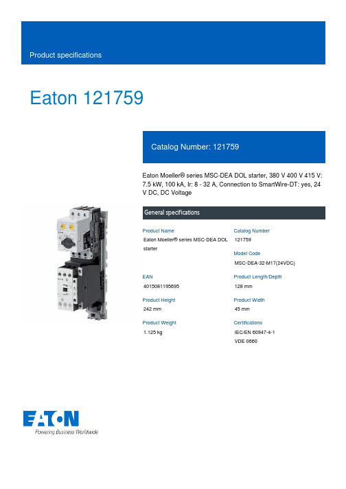
Eaton 121759Eaton Moeller® series MSC-DEA DOL starter, 380 V 400 V 415 V: 7.5 kW, 100 kA, Ir: 8 - 32 A, Connection to SmartWire-DT: yes, 24 V DC, DC VoltageGeneral specificationsEaton Moeller® series MSC-DEA DOL starter121759MSC-DEA-32-M17(24VDC)4015081195695128 mm 242 mm 45 mm 1.125 kgIEC/EN 60947-4-1 VDE 0660Product NameCatalog Number Model CodeEANProduct Length/Depth Product Height Product Width Product Weight Certifications17 AIs the panel builder's responsibility. The specifications for the switchgear must be observed.7.5 kW230 - 415 V AC0 A0 VMeets the product standard's requirements.Is the panel builder's responsibility. The specifications for the switchgear must be observed.DIN rail≤ 500 ms, main conducting paths, AC-4 cycle operationDoes not apply, since the entire switchgear needs to be evaluated.0 kW0 kWMeets the product standard's requirements.24 VShort-circuit release Simple, flexible and safe! Distribution system for motor-starter combinationsSave time and space thanks to the new link module PKZM0-XDM32ME Motor Starters in System xStart - brochureProduct Range Catalog Switching and protecting motorsDA-DC-00004245.pdfDA-DC-00004109.pdfeaton-manual-motor-starters-dol-starter-msc-d-dimensions.epseaton-manual-motor-starters-mounting-msc-d-dol-starter-3d-drawing.eps eaton-manual-motor-starters-dol-starter-msc-d-3d-drawing-002.eps eaton-general-ie-ready-dilm-contactor-standards.epsDA-CE-ETN.MSC-DEA-32-M17(24VDC)IL03402010ZWIN-WIN with push-in technologyDA-CS-msc_de_bg2DA-CD-msc_de_bg2eaton-manual-motor-starters-msc-d-dol-starter-wiring-diagram.epsRated operational current for specified heat dissipation (In) 10.11 Short-circuit ratingRated operational power at AC-3, 380/400 V, 50 Hz Rated operational voltageRated conditional short-circuit current, type 1, 480 Y/277 V Rated control supply voltage (Us) at AC, 50 Hz - min10.4 Clearances and creepage distances10.12 Electromagnetic compatibilityMounting methodCut-out periods - min10.2.5 LiftingRated power at 575 V, 60 Hz, 3-phaseRated power at 460 V, 60 Hz, 3-phase10.2.3.1 Verification of thermal stability of enclosures Rated control supply voltage (Us) at DC - minFitted with:BrochuresCatalogs Certification reports DrawingseCAD model Installation instructions Installation videos mCAD modelWiring diagramsCurrent flow times - min700 (Class 10) AC-4 cycle operation, Main conducting paths 1000 (Class 20) AC-4 cycle operation, Main conducting paths For all combinations with an SWD activation, you need not adhere to the minimum current flow times and minimum cut-out periods.500 (Class 5) AC-4 cycle operation, Main conducting paths900 (Class 15) AC-4 cycle operation, Main conducting paths Note: Going below the minimum current flow time can cause overheating of the load (motor).Number of pilot lightsRated control supply voltage (Us) at AC, 50 Hz - max0 VCoordination type210.8 Connections for external conductorsIs the panel builder's responsibility.Coordination class (IEC 60947-4-3)Class 2Rated conditional short-circuit current, type 1, 600 Y/347 V0 AAmbient operating temperature - max55 °CRated operational power at AC-3, 220/230 V, 50 Hz4 kWConnection to SmartWire-DTIn conjunction with PKE-SWD-32 SmartWire DT PKE module YesNumber of command positionsStatic heat dissipation, non-current-dependent Pvs0.86 WElectrical connection type of main circuitScrew connectionRated conditional short-circuit current (Iq), 500 V50 AElectrical connection type for auxiliary- and control-current circuit Screw connectionPower consumption (sealing) at DC0.86 WRated control supply voltage (Us) at DC - max24 V10.9.3 Impulse withstand voltageIs the panel builder's responsibility.Ambient operating temperature - min-25 °C10.6 Incorporation of switching devices and componentsDoes not apply, since the entire switchgear needs to be evaluated.10.5 Protection against electric shockDoes not apply, since the entire switchgear needs to be evaluated.ClassAdjustable10.13 Mechanical functionThe device meets the requirements, provided the information in the instruction leaflet (IL) is observed.10.2.6 Mechanical impactDoes not apply, since the entire switchgear needs to be evaluated.10.9.4 Testing of enclosures made of insulating materialIs the panel builder's responsibility.10.3 Degree of protection of assembliesDoes not apply, since the entire switchgear needs to be evaluated.Heat dissipation per pole, current-dependent Pvid2.7 WActuating voltage24 V DCVoltage typeDCOverload release current setting - min8 AEquipment heat dissipation, current-dependent Pvid8.2 WHeat dissipation capacity Pdiss0 WRated operational current (Ie)16.7 ASuitable forAlso motors with efficiency class IE3Number of auxiliary contacts (normally closed contacts)1Rated conditional short-circuit current (Iq), type 2, 380 V, 400 V, 415 V100000 A10.2.3.2 Verification of resistance of insulating materials to normal heatMeets the product standard's requirements.10.2.3.3 Resist. of insul. mat. to abnormal heat/fire by internal elect. effectsMeets the product standard's requirements.Rated operational power at AC-3, 500 V, 50 Hz7.5 kWProtocolOther bus systemsOverload release current setting - max32 A10.9.2 Power-frequency electric strengthIs the panel builder's responsibility.Overvoltage categoryIIIDegree of protectionIP20NEMA OtherPollution degree3Rated control supply voltage (Us) at AC, 60 Hz - min0 V10.7 Internal electrical circuits and connectionsIs the panel builder's responsibility.Rated impulse withstand voltage (Uimp)6000 V ACConnectionScrew terminals10.10 Temperature riseThe panel builder is responsible for the temperature rise calculation. Eaton will provide heat dissipation data for the devices.FunctionsTemperature compensated overload protectionRated operational current (Ie) at AC-3, 500 V12.1 ARated conditional short-circuit current (Iq), type 2, 230 V 100000 ATypeStarter with electronic trip unit10.2.2 Corrosion resistanceMeets the product standard's requirements.10.2.4 Resistance to ultra-violet (UV) radiationMeets the product standard's requirements.10.2.7 InscriptionsMeets the product standard's requirements.Short-circuit release (Irm) - max496 ARated control supply voltage (Us) at AC, 60 Hz - max0 VRated operational current (Ie) at AC-3, 380 V, 400 V, 415 V 17 AModelDirect starterNumber of auxiliary contacts (normally open contacts)Eaton Corporation plc Eaton House30 Pembroke Road Dublin 4, Ireland © 2023 Eaton. All Rights Reserved. Eaton is a registered trademark.All other trademarks areproperty of their respectiveowners./socialmedia。
Eaton HEV技术背景文件说明书

Eaton and Hybrid Electric Vehicle Powertrains- Past, Present, and FutureEaton’s HEV Roots Go DeepEaton Corporation has been involved in the evolution of electric and hybrid vehicles for over 20 years. During the late 1970s and throughout the 1980s, Eaton was heavily engaged in electric vehicle research and development helping to pioneer important technological advances such as the migration from brush-type DC motors to brush-less induction motors. Early projects included the installation of complete electric traction drive systems into Ford and Chrysler passenger car and light truck applications. In the late 1980s, Eaton put its electric vehicle program on hold because of the gap in commercially viable battery technologies. This proved to be a wise decision, since most electric vehicle programs were dropped throughout the industry during the ‘90s and replaced with hybrid electric and fuel cell vehicle programs.During this time, as Eaton continued to monitor these developments, they became convinced that battery technology for hybrid electric applications was approaching commercial viability. At the same time, forward-thinking end users and truck OEM customers were becoming more receptive to the idea of hybrid electric vehicles (HEV).Eaton Forms HEV Business Unit- Sharpens FocusIn January 2000, Eaton launched itself into the HEV world with an internally funded R&D program aimed at building a Class 7 prototype hybrid truck. In March 2000, Eaton formed an HEV powertrain business unit within their Truck Electronic Systems Division, focusing human talent and resources toward the development of commercially viable hybrid powertrain systems. The successful demonstration of the Class 7 prototype in November 2000 paved the way for a second prototype, aimed at the urban P&D segment in the Class 4 range, to be built in 2001.In late 2000, Eaton began to seek key partnerships with strategic fleets such as FedEx. During this time Eaton learned of FedEx Express’ plans to issue a Request for Information that was aimed at a Class 4 hybrid electric delivery step-van. Within just a few months, Eaton submitted a competitive proposal in response to an industry-wide Request for a Proposal issued by FedEx Express.On February 26, 2002, FedEx Expressannounced that it had selected three finalists--including Eaton-- in its search for a prototypeversion of a hybrid electric Class 4 step-van.Eaton delivered its prototype to FedEx inSeptember 2002, and that fall, was selected asthe sole supplier of 18 HEV powertrainprototypes to be installed in FedEx vehicles fortesting in four major metropolitan areas. At apress event in Washington D.C. in May 2003,FedEx Express proclaimed its leadership in the adoption of hybrid power in its fleet of Class 4 delivery vehicles, in cooperation with its powertrain supplier Eaton Corporation and advocacy group Environmental Defense.U.S. Senator Orrin Hatch (R-Utah) congratulates FedEx Express, Environmental Defense andEaton for launching an advanced technology vehicle that is "a bellwether for the rest of the nation and the world."Adding importance to the event were appearances by U.S. Senator Orin Hatch (R-Utah) and Environmental Protection Agency director Christine Todd-Whitman, both hailing the announcement as a real and positive step towards the adoption of fuel-saving and pollution-reducing technologies.Meanwhile, in September 2002, Eaton was awarded a $7.1 million contract to lead a project in the Advanced Heavy Hybrid Propulsion System (AHHPS) Program sponsored by the U.S. Department of Energy. Through this program Eaton, in partnership with International Truck & Engine, will develop a heavy hybrid propulsion system designed to increase fuel efficiency and decrease emissions for commercial vehicles in the Class 4-7 weight range. Recently, a prototype UPS urban delivery vehicle was built using this new system and is currently in the testing stage.At the state capitol ceremony in SacramentoFedEx Express President David Bronczek explains the FedEx hybrid program to California Governor Arnold Schwarzenegger while Eaton’sJim Sweetnam and Fred Krupp of EnvironmentalDefense look on. On March 30, 2004, at a state capitol ceremonyin Sacramento, CA, FedEx Express, incollaboration with Sacramento Metropolitan AirQuality Management District and EnvironmentalDefense, placed the first of 18 Eaton hybridelectric powered delivery vehicles into service.The official rollout of the FedEx OptiFleet E700took place on the capitol steps with CaliforniaGovernor Arnold Schwarzenegger inattendance. Since late February, two FedExOptiFleet vehicles have been tested in theSacramento area to demonstrate thecommercial viability of the lower-emissionpowertrain in heavy-duty vehicles. Throughout the rest of 2004, Eaton will be placing an additional 16 trucks into service in selected cities. These trucks will endure real-world FedEx operating conditions to verify and provetheir viability in commercial applications.In May 2004, Eaton, in collaboration with International Truck and Engine, submitted a proposal to build a hybrid electric drive system for heavy-duty utility trucks. The proposal was submitted in response to a Request for Proposal from the HTUF Utility Hybrid Truck Working Group (Hybrid Task Force). Before submitting their proposal Eaton and International conducted several “Day-in-the-Life” sessions with members of the HTUF Utility Task Force Fleets. These sessions were held to better understand how the equipment is used in the field and have directly impacted the proposed design. In August 2004, the HTUF Working Group notified Eaton and International that their proposal had been selected.In October 2004, Eaton will host the fourth annual national meeting for the Hybrid Truck Users Forum (HTUF) in Kalamazoo, MI. In addition to hosting the event, Eaton will showcase several HEV commercial vehicle prototypes of varying vocations with a “ride-and-drive” at the Eaton Proving Grounds in Marshall, MI.Eaton’s Hybrid Mission & StrategyHybrid electric systems are critical to the automotive and truck industry’s technological roadmap that ultimately leads to fuel cell powertrains and beyond. The successful introduction of electric motor drives, inverters, energy storage devices and advanced power management controls on HEVs will pave the way for future migration to fuel cell powertrains.Eaton recognizes that in order to be commercially viable, hybrid electric vehicles will need to deliver significant fuel savings and environmental benefits. They are convinced that the most successful hybrid products will have the lowest price premiums compared to conventional vehicles as well as demonstrate exceptional reliability “out-of-the-box.” These objectives are what drives Eaton’s commitment to develop a hybrid electric system that will enable truck OEMs and engine manufacturers to comply with strict emissions regulations, reduce fuel consumption, improve drivability and increase functionality by providing on-board electrical power generation.By combining their successful automated manual transmission and clutch products with electric motor drives and related components, Eaton will be able to create integrated hybrid drivetrain units that are attractive to various commercial truck segments.Product Strategy: Series Vs. ParallelWhen building an HEV powertrain there are two basic configurations: series and parallel.• A “series” configuration has a generator mounted directly to the engine. All power from the engine is converted directly into electrical energy, which is then used to drive traction motors at the axle or wheel ends. In this type of design there is no mechanical drive path between the engine and the drive wheels.• A “parallel” configuration maintains conventional mechanical drivetrain architecture, but adds the ability to augment engine torque with electrical horsepower. A parallel system provides operating redundancy not found in a series system, whereby the conventional power can continue to operate in the event of an electrical power malfunction.Eaton is focused on developing parallel-hybrid drivetrainsystems that provide the best cost-benefit balance formany commercial truck applications. Most hybridsuppliers began working on series-hybrid systems andhave since transitioned to parallel hybrid architecture forsimilar reasons.Eaton’s first prototype truck featured a Full Hybridsystem that made it possible to operate the engineindependently from the vehicles’ road load conditions.This freedom was accomplished by combining a CVT-like device with an electric motor used to fill the gap between the most desirable engine operating conditions and the vehicle operating demands. The Full Hybrid An Eaton Fuller automated medium-duty transmission is fitted with an automated clutch and an electric motor-generator in the latest prototype.architecture provides the maximum potential for reducing fuel consumption and exhaust emissions of commercial trucks.Eaton’s second prototype truck features a Direct Hybrid system that incorporates an electric motor/generator located between the output of an automated clutch and the input to the AutoShift® transmission. This architecture makes it possible to recover energy normally lost during braking and store that energy in batteries or other devices. Electric torque can be blended with engine torque to improve vehicle performance and to operate the engine in the most fuel-efficient range for a given speed or to operate the vehicle with electric power only. In addition, this configuration creates a built-in power generator function into the vehicle for applications where remote power may be critical. Finally, this design provides a level of redundancy by enabling the vehicle to operate in electric-only or engine-only modes if the other system experiences a failure.Product and Technology DevelopmentHybrid electric vehicles require an unprecedented level of integration and partnership between truck OEMs, the engine manufacturer, and the suppliers of the drivetrain and major electrical components. Eaton’s strategy includes early and significant collaboration with truck OEMs, engine manufacturers and key technology/component suppliers.Eaton plans to offer complete, integrated Hybrid Drive Units to truck OEMs that include automated clutch, electric motor/generator, motor controller/inverter, energy storage, automated manual transmission, and an integrated supervisory Hybrid Control Module.Eaton’s HEV vision includes the Hybrid Drive Unit, which includes an automated clutch, a motor/generator,automated transmission and inverter/controls, as well as the supervisory Hybrid Control Module.HEV: Commercial StatusMany industry observers believe that hybrid electric technology is readily available. They point to the increasing popularity of passenger cars like the Toyota Prius and the Honda Insight as examples of successful passenger car applications. Recent moves by the transit departments in New York City and Seattle to purchase hundreds of hybrid electric transit buses are cited as examples of successful heavy hybrid vehicle application. Since most commercial trucks fall between the gross vehicle weights of these two hybrid examples, shouldn’t commercial trucks be an easy next step?Eaton, in partnership with International Truck & Engine, was recently selected by WestStart’s Hybrid Truck Users Forum (HTUF) to manufacture more than 20 advanced, pre-production hybrid-electric work trucks for national deployment and assessment.This is the first announcement by a U.S. truck OEM regarding production plans for Class 4-8 (light, medium and heavy-duty) hybrid vehicles. Unlike city buses and passenger cars, commercial trucks are subject to unique durability, reliability and operating requirements and expectations. For example, a typical passenger car’s useful life of 100,000 to 125,000 miles is not even close to being acceptable for commercial truck applications. Many commercial fleets put 100,000 miles or more on a truck in a single year. Other fleets may keep their trucks for 10 years or more.Today, the use of hybrid electric technology in commercial trucks faces many challenges. From a technological standpoint, these challenges include hybrid electric systems being able to create the increased torque and horsepower required in medium or heavy-duty trucks. The durability and reliability of battery systems and motor/inverter components must be proven in hybrid applications where battery cycles and operating environments are consistent with actual commercial truck field conditions before truck OEMs will invest in product development programs leading to production release. Furthermore, the production volumes of commercial trucks are much smaller than passenger cars, making it more difficult to recover the R&D and tooling investment. Thus, strong business cases from both the fleet operator and OEM manufacturer’s perspectives must be demonstrated before truck OEMs will commit to large investments. For these and other reasons, successful commercialization of hybrid electric trucks will require government support of initial technological development and demonstration of reliability in the field. In 2000, four federal government departments and 16 industrial partners, including Eaton, formed the 21st Century Truck Partnership to address these issues.The 21st Century Truck Partnership was formed to bring industry and the government together in research and development efforts and share the associated costs. The role of the federal agencies is to build on existing research and to assign priority to major new research identified by the Partnership. These research efforts will address concerns specific to all trucks, tractor-trailers, transit buses and military vehicles.Currently, Eaton is engaged in planning discussions with certain truck OEMs, engine manufacturers and key early adopter fleets. Increasingly, these discussions focus on characterizing sales volume forecasts and component cost structures required for successful commercialization.Eaton Hybrid In The NewsEaton’s rapid progress in hybrid power technology over the last two years has earned visibility not only in its own market, but by the general public as well. In addition to being featured in trucking industry news and environmental journals for its groundbreaking efforts, Eaton has also been featured along with its teammates FedEx Express and Environmental Defense on CNN and CNN Headline News, as well as CNBC, MSNBC, the New York Times and other national and international media.SummaryEaton has established a Hybrid Electric Powertrain business unit and is investing aggressively in the technology and product development necessary to develop commercially attractive solutions for cost effective, reliable hybrid drive systems. At present, Eaton is optimistic that battery durability, reliability and cost will improve to the point where these systems are attractive for commercial fleet customers. In the meantime, aggressive government R&D funding and purchasing incentives are essential to bridge the gaps between today’s technology and a significant hybrid penetration in the future.###。
伊顿混合动力介绍General Hybrid Overview For ZT -CN
16
美国能源部项目
早期提供样车的目的: • 型式认可 • 客户反馈 • 可靠性评估
CSVT 设计: • 先进的部件及整合系统 • 提升燃油经济性 • 确保可靠性和耐久性
发动机 变速箱 电机 电池 逆变器 电器附件 Front End Accessory Drive (FEAD) 电路结构
先进的控制系统
接合
电动机
AutoShift (AMT)
混合扭矩
驱动扭矩
放电模式
电池组
柴油机和电动机共同驱动模式 (电机助力)
Proprietary & Confidential
9
运行模式
发动机
自动离合器
发动机 扭矩
发电机
AutoShift (AMT)
发动机 扭矩
驱动扭矩
接合
充电模式(选择)
电池组
柴油机单独驱动模式 (备用)
Proprietary & Confidential
10
运行模式
发动机
自动离合器
发动机 扭矩
发电机
AutoShift (AMT)
再生制 动扭矩
惯性扭矩
结合或分开
充电模式
电池组
再生制动模式
Proprietary & Confidential
11
伊顿混合动力系统好处
• 只有一个电机和逆变器 – 低成本,高可靠性 • 电机有良好的低速高扭矩特性 (能够很好的与柴油发动机 匹配) – 在发动机工作转速内具有很高的效率 – 最大转速2500rpm(44kW & 420 Nm) – 性能优越,每加仑油耗行驶的里程长 • 直接驱动结构 – 系统简化, 成本低, 可靠性高 – 发动机单独驱动模式可作为备用
Eaton 一体化电源系列 Type NR 油液开关说明书

GeneralEaton offers its Cooper Power™ series Type NR oil switch for switching inductive and capacitor currents, to meet the requirements of a wide range of applications. This switch is an electrically operated, single-phase switch. The switch also includes an operating handle for switch position indication or manual operation. Thenormal operation of this switch is managed with an electric motor requiring low-voltage input. Eaton offers two options for the electric motor, either 120 Vac, 60 Hz or 240 Vac, 60 Hz. The switch operation can be managed remotely, via electrical or electronic controls, or manually at the installation site when needed.Electrically operated Type NR oilswitchFigure 1. Untanked T ype NR oil switch.DescriptionThe Type NR oil switch is a single-phase device for use ondistribution circuits. Compact design makes these switches ideal for use on capacitor banks, especially pole-top installations. These switches are electrically operated and can be controlled by various electrical or electronic devices. An operating handle, which also serves as a contact position indicator, is provided for manually opening and closing the switch.otee:N The Type NR oil switch may not be manually closed into a faulted line. The making current rating to these switches applies to electrical operation only.Capacitor bank switching The standard Type NR single-phase oil switch is rated at 15.0 kV / 95 kV BIL and is capable of switching three-phase capacitor banks up to 3600 kVAR on 14.4 kV systems; with three (3) switches controlledby customer. Choosing the 125 kV BIL option enables switchingsolidly grounded capacitor banks up to 6400 kVAR on multigrounded wye systems up to 14.4 / 24.9 kV; with three (3) switches controlled by customer.The 22.0 kV / 125 kV BIL version of the Type NR oil switch can switch solidly grounded three-phase capacitor banks up to 2700 kVAR on 20 / 34.5 kV multigrounded-wye systems; with three (3) switches controlled by customer. OperationWith switch contacts closed, selecting the "OPEN SWITCH", or similar, position in the switch controls energizes the switch opencontacts on the electric motor. Through a gear and lever system, this releases a toggle which allows pre-loaded opening springs to snap open the switch contacts; loads a heavy spring in preparation for aclosing operation; positions selector switch contacts so that only the closing circuit can subsequently be energized; and interrupts the electric motor operating current when the first three functions have been completed. The opening circuit must remain energized for 4.0seconds.Similarly, selecting the "CLOSE SWITCH", or similar, position in theswitch controls energizes the switch close contacts on the electric motor. This releases the closing spring to close switch contacts and load opening springs; positions selector switch contacts for the subsequent opening signal, then interrupts the operating electricmotor current. The closing circuit must remain energized for 0.5 seconds.BUSHING TERMINALSaluminum conductors, either vertically or horizontallyLIFTING STRAPconvenient for hoisting entire switch or for lifting mechanism from tankACTUATOR HOUSINGmotor-driven mechanism for electri-cally opening and closing the switchSTATIONARY CONTACTSand durable arcing tips, accessible for easy inspection or cleaningBUSHINGSwet-process porcelain with light-gray glaze. Munsell Gray 70SLEET HOODprotects manual operat-ing handle: switch data permanently affixed on nameplateO-RING GASKETin confined assembly provides weather-proof head-tank sealallows hookstick operation and serves as contact position indicator* General purpose duty switches are rated for both capacitive and inductive current switching applications.T able 1. Summary of RatingsSwitch TypeApplicationMaximumOperating Voltage (kV)Rated Switching Current (A)NR General Purpose Duty15.0200*NRV22.0602Catalog Data CA230007ENEffective August 2015Electrically operated T ype NR oil switch/cooperpowerseriesT able 2. Ratings and SpecificationsDescriptionStandard15 kV with 17" Creepage15 kV with 125 kV BIL22 kVMaximum Design Voltage, kV 15.015.015.022.0Nominal Operating Voltage, kV 2.4-14.4 2.4-14.4 2.4-14.420.0Basic Insulation Level (BIL), kV 959512512560 Hertz Withstand Voltage, kV Dry, One Minute Wet, Ten seconds3530353042366050Continuous Current Rating, Amps20020020060Load Interrupting Ability (Inductive), Symmetric Amps 75-100% power factor 50-75% power factor < 50% power factor20010050A 20010050A 20010050A 606060Maximum Capacitive Current, Amps (parallel bank-max)200200200*60* High Frequency Transient Current, Amps 12000120001200012000 Transient Frequency, Hz 6000600060006000 High Frequency Damping Factor .40-.55.40-.55.40-.55.40-.55Momentary Rating, Amps asym.9000900090009000Short Time Current Amps 1/2 second,sym. 1 second, sym.60004500600045006000450060004500Close and Latch Rating, Amps asym.9000900090009000T able 3. Electrical Data (Control)DescriptionRatingNominal operating voltage (50/60 Hz only) (Vac)120240Operating voltage range (Vac)95-130190-260Closing-motor current (A)1.9.7Switch response time, opening (sec) 4.0 4.0Switch response time, closing (sec)0.50.5*The 125 kV BIL switch and the 22.0 kV switch are rated for single bank switching only.3Catalog Data CA230007ENEffective August 2015Electrically operated T ype NR oil switch /cooperpowerseriesT able 4. Basic NR and NRV Oil SwitchesDescriptionNominal/Maximum Voltage (kV)Continuous Current (A)Switch BIL (kV)Type NR Oil Switch 14.4/15.020095*Type NRV Oil Switch20.060125* 125 kV BIL option available for standard NR oil switchOrdering informationWhen ordering the Type NR electrically operated oil switch specify the Voltage Rating from Table 4. The basic Type NR oil switch is designed with a maximum operating voltage of 15.0 kV L -L with a continuous current rating of 200 A. The Type NRV oil switch is designed with a maximum operating voltage of 22.0 kV with a continuous current rating of 60 A.T able 5. NR / NRV Motor Control VoltageDescription120 Vac Actuating Motor (Standard)240 Vac Actuating MotorControl voltage requirementsSpecify the Type NR motor control voltage from Table 5. The Type NR oil switch is supplied with a 120 Vac motor control voltage as standard.T able 6. NR / NRV Switch BIL & Bushing Creep*DescriptionRating (kV)BIL (kV)Bushing Creep (in)NR Oil Switch 15.09512.0NR Oil Switch 15.09517.0NR Oil Switch 15.012516.0NRV Oil Switch22.012517.0Insulation and creep requirementsSpecify the NR oil switch insulation level and porcelain insulator creep using Table 6. The NR oil switch is designed with 95 kV BIL insulation level as a standard option with a porcelain bushing having 12 inches of creep. The 95 kV BIL insulation level is only available in the NR oil switch. The NRV oil switch has an insulation level of 125 kV BIL and a porcelain bushing with 17.0" of creep as a standard offering.T able 7. NR / NRV T ank OptionsDescriptionSwitch Rating (kV)Standard Tank 15.022.0Stainless Steel Tank 15.022.0Zinc Plated Tank15.022.0Specialized tank requirementsSpecify the required NR tank option from Table 7. The standard tank is manufactured from a mild formed steel and painted toprotect against the environment. There are available options for zinc plating and stainless steel tanks for highly corrosive and salt-fog contaminated environments.T able 8. NR / NRV Low Voltage ArresterDescriptionNone (Std)120 Vac Surge Arrester (Factory Installed)Surge protection requirementsThere is an available option for a factory-installed 120 Vac low voltage surge arrester to protect the motor control circuit from damaging effects of lightning. The arrester rating is determined by the motor control voltage. Contact the factory if a 240 Vac low voltage arrester is required.T able 9. NR / NRV Auxiliary SwitchDescriptionNone (Std)Auxiliary SwitchAuxiliary switch requirementsSpecify the Auxiliary switch from Table 9 if necessary for theswitching application. The Auxiliary switch is a SPDT switch, which allows the user to remotely obtain the close or open position of the Type NR oil switch.*Reference Figure 4 on page 9 for outline dimensions of the extra creep bushing"* Determined by motor control voltage4Catalog Data CA230007ENEffective August 2015Electrically operated T ype NR oil switch/cooperpowerseriesT able 10. NR / NRV Hold SwitchDescriptionNone (Std)Hold SwitchHold switch requirementsSpecify the Hold switch from Table 10 if necessary for theapplication. The close or open signals supplied to the Type NR oil switch must be applied for a minimum of 4.5 seconds. Specify the Hold switch option from Table 10 if the capacitor switchingapplication requires a signal for less than 4.5 seconds. The close or open signal has to be applied for 1 second for proper operation of the Type NR oil switch.T able 11. Factory-wired ReceptaclesDescription5-pin/3-conductor receptacle for standard three-wire control 6-pin/6-conductor receptacle for auxiliary switchReceptacle assembly requirementsSpecify the type of receptacle from Table 11 for the switchingapplication. The receptacle assemblies are mounted in the bottom of the actuator housing and provide a convenient, weather-proof connection to switch the control circuits. Receptacles are supplied with 5-pin. 3-conductor or 6-pin, 6-conductor configurations. Reference Figure 2 for 5-pin or 6-pin receptacle orientations. Consult the factory for additional receptacle options.5-pin Receptacle6-pin ReceptacleFigure 2. Receptacle assembly schematic.* Consult factory for available receptacle options5Catalog Data CA230007ENEffective August 2015Electrically operated T ype NR oil switch /cooperpowerseriesT able 13. Wildlife Protectors for T erminal BushingsDescriptionCatalog NumberNone (Std)–Wildlife Protectors (95 kV BIL Only)*CCM32A1Wildlife Protectors (125 kV BIL only)*CCM33A1Wildlife protector requirementsSelect required wildlife protectors based on the Type NR switch being ordered for the application. Wildlife protectors protect the energized terminals of the Type NR switch from incidental contact from wildlife, tree branches or line crews performed routinemaintenance of overhead equipment. Wildlife protectors must be ordered in a quantity of 2.T able 14. Mounting OptionsDescriptionCatalog NumberNone (Std)–NEMA ® X-Arm BrktHA00039Mounting option requirementsSelect the Type NR oil switch mounting method from Table 14. The standard Type NR switch is supplied with an integral bracket, which is used for pole-mounting or capacitor rack applications. A NEMA ®-style bracket is available for cross-arm applications.T able 12. Mating Plug and Conductor Cable OptionsDescriptionCatalog Number5-Pin Mating PlugCCR010P15-Pin / 3-Conductor Cable (6 ft)CCR003P65-Pin / 3-Conductor Cable (8 ft) CCR003P85-Pin / 3-Conductor Cable (10 ft) CCR003P105-Pin / 3-Conductor Cable (12 ft) CCR003P125-Pin / 3-Conductor Cable (14 ft) CCR003P145-Pin / 3-Conductor Cable (16 ft) CCR003P165-Pin / 3-Conductor Cable (18 ft) CCR003P185-Pin / 3-Conductor Cable (20 ft) CCR003P205-Pin / 3-Conductor Cable (22 ft) CCR003P225-Pin / 3-Conductor Cable (24 ft) CCR003P245-Pin / 3-Conductor Cable (26 ft) CCR003P265-Pin / 3-Conductor Cable (28 ft) CCR003P285-Pin / 3-Conductor Cable (36 ft) CCR003P366-Pin Mating PlugCCR009P16-Pin / 6-Conductor Cable (6 ft) CCR006P66-Pin / 6-Conductor Cable (8 ft) CCR006P86-Pin / 6-Conductor Cable (10 ft) CCR006P106-Pin / 6-Conductor Cable (12 ft) CCR006P126-Pin / 6-Conductor Cable (14 ft) CCR006P146-Pin / 6-Conductor Cable (16 ft) CCR006P166-Pin / 6-Conductor Cable (18 ft) CCR006P186-Pin / 6-Conductor Cable (20 ft) CCR006P206-Pin / 6-Conductor Cable (22 ft) CCR006P226-Pin / 6-Conductor Cable (24 ft) CCR006P246-Pin / 6-Conductor Cable (26 ft) CCR006P266-Pin / 6-Conductor Cable (28 ft)CCR006P286-Pin / 6-Conductor Cable (36 ft)CCR006P36Mating plug & conductor cable requirementsSpecify the type of mating plug and conductor cable configuration and length from Table 12 if required for the switching application.5-pin plugs accommodate up to 12 AWG wire and 0.375-0.500 inch O.D cables to allow connection to the 5-pin receptacle.6-pin plugs accommodate up to 16 AWG wire and 0.500-0.625 inch O.D cables to allow connection to 6-pin receptacles. The number of conductors tabulated for the receptacles in Table 12 above indicates the number of pins wired to the actuator terminal strip. Mating plugs are available as an accessory and should be ordered separately. Consult the factory for additional mating plug and conductor cable options.* Consult factory for additional Conductor C able options* Must be ordered in a quantity of (2)6Catalog Data CA230007ENEffective August 2015Electrically operated T ype NR oil switch/cooperpowerseriesStandard Type NR Oil Switch Catalog Number ConfigurationThe standard Type NR and NRV configurations are provided below. If you need Engineered To Order (ETO) models, please contact your Eaton representative for details.Table 4-S witch TypeNR (15 kV)Type NR (15.0 kV) CCM17B2-GType NRV (22.0 kV)CCM75B2-GTable 5-Control Motor120 Vac (Std)Table 6-BIL & Creep*95 kV BIL (15.0 kV Only)Table 7-Tank OptionsStandard TankTable 8-L V Surge ArresterNone (Std)Table 9-Auxiliary SwitchNone (Std)Table 10-Hold SwitchNone (Std)Table 11-Receptacle5 -Pin / 3-Conductor (Std)Table 12-Plug & CableNone (Std)Table 13-Bird GuardsW/O Bird Guards (Std)Table 14-Mounting OptionsNone (Std)Table 4-S witch TypeNRV (22.0 kV)Table 5-Control Motor120 Vac (Std)Table 6-BIL & Creep*125 kV BILTable 7-Tank OptionsStandard TankTable 8-L V Surge ArresterNone (Std)Table 9-Auxiliary SwitchNone (Std)Table 10-Hold SwitchNone (Std)Table 11-Receptacle5 Pin / 3-Conductor (Std)Table 12-Plug & CableNone (Std)Table 13-Bird GuardsW/O Bird Guards (Std)Table 14-Mounting OptionsNone (Std)*Reference Figure 3 on page 8 for NR oil switch outline dimensions*Reference Figure 5 on page 10 for NRV outline dimensions7Catalog Data CA230007ENEffective August 2015Electrically operated T ype NR oil switch /cooperpowerseriesFOR FACTORY-WIRED RECEPTACLEFigure 3. Outline dimensions of 95 kV BIL T ype NR oil switch with standard bushings, (15.0 kV Rating ONL Y).8Catalog Data CA230007ENEffective August 2015Electrically operated T ype NR oil switch/cooperpowerseriesFigure 4. Outline dimensions of 95 kV BIL T ype NR oil switch with 17" creepage bushings, (15.0 kV Rating ONL Y).9Catalog Data CA230007ENEffective August 2015Electrically operated T ype NR oil switch /cooperpowerseriesFOR FACTORY-WIRED RECEPTACLEFigure 5. Outline dimensions of 125 kV BIL T ype NR oil switch (15.0 and 22.0 kV).10Catalog Data CA230007ENEffective August 2015Electrically operated T ype NR oil switch/cooperpowerseriesCatalog Data CA230007EN Electrically operated T ype NR oil switchEffective August 201511/cooperpowerseriesElectrically operated T ype NR oil switch Eaton 1000 Eaton Boulevard Cleveland, OH 44122United States Eaton’s Cooper Power Systems Division 2300 Badger Drive Waukesha, WI 53188United States /cooperpowerseries© 2015 Eaton All Rights Reserved Printed in USA Publication No. CA230007EN Catalog Data CA230007EN Effective August 2015Eaton is a registered trademark.All other trademarks are property of their respective owners.For Eaton's Cooper Power series Type NR oil switch product information call 1-877-277-4636 or visit: /cooperpowerseries.。
- 1、下载文档前请自行甄别文档内容的完整性,平台不提供额外的编辑、内容补充、找答案等附加服务。
- 2、"仅部分预览"的文档,不可在线预览部分如存在完整性等问题,可反馈申请退款(可完整预览的文档不适用该条件!)。
- 3、如文档侵犯您的权益,请联系客服反馈,我们会尽快为您处理(人工客服工作时间:9:00-18:30)。
+ kkWkWW
T
相同的扭矩输 出
发动机
(小马力)
T
电机/发电机
3
伊顿混合动力系统介绍-混合动力系统示意图
Battery 电池
Inverter/Controls 逆变器及其控制装置
Hybrid Drive Unit 混合动力驱动系统
Engine 发动机
Auto
Clutch 自动离合器
Motor/
90多台配有伊顿混合动力系统 的联邦快递车E-700投入使用
UPS订购50套配有伊顿混 合动力系统的箱式货车
UPS orders 50 Eatonpowered Hybrid Vans
伊顿混合动力系统配套Peterbilt公共事业车
Eaton Hybrid Peterbilt Utility truck
• 车辆性能参数
• 确定车辆的动力性能指标 • 仿真检验 • 最终确定动力总成参数
• 设计
• 整体机械设计 • 电池盒设计(仅限于4电池系统) • 冷却系统设计 • 线束设计
• 元件采购 • 样车建造 • 控制开发/调试 • 实验测试 • 公告申请 • 培训 • 路试 • 产品化
27
混合动力开发一般流程
联邦快递项目竞标 FedEx Competition
伊顿赢得联邦快递的订单 Eaton Wins FedEx Competition
设计检验与核实 Design Measured & Validated
美国能源部和国家可再生能源 实验室新一代研发项目
DOE/NREL Next Generation R&D Program
伊顿公司密切关注行业 发展,技术进步及客户 需求
Eaton monitors industry, technologies and Voice of the Customer
伊顿公司成立混合动力事业部 Eaton forms Hybrid Power systems business unit
4级箱式货车样车 Class 4 Step Van Prototype
6
伊顿混合动力系统的优点 – 锂离子动力电池
• 201所测试结果显示单体电池充放电功 率很高, 堪比超级电容器.
• 锰基, 安全性好, 且安全保护控制措施 极其详尽.
• 损耗极低, 效率高, 风冷即可 • 先进可靠的电池管理系统 • 无需人工筛选单体电池, 且电池管理系
统可在实用过程中自动平衡各单体电池 的电压 • J1939CAN总线兼容 • 故障诊断功能全面 • 重量轻, 寿命长
4
伊顿混合动力系统的优点 - 系统
• 集成式结构设计 - 基于伊顿成熟的机械式自动变速器 和先进的干式自动离合器. 紧凑, 安装及维护方便
• 采用 “直接式” 并联结构
• 效率高, 所需电驱动元件功率小,成本缩减
• 复杂性降低, 含发动机单独驱动模式, 可靠性高 • 仅含1个电机和逆变器 ---- 成本低,可靠性高 • 低速大扭矩永磁电机 ----- 2600转/分, 44KW及420NM,
Generator 电动机/发电
机
Transmission 变速箱
Brakes
(ABS) 制动器 (防抱死系统)
Supervisory
Powertrain Control 动力传动系统总控制器
Partners 合作伙伴
Eaton 伊顿
Software Application for
Each Engine MFR & Truck OEM 面向不同发动机制造商和卡车制造商的 应用软e Cycle Costs
减少油耗
Improved Fuel Economy
减少刹车磨损
Reduced Brake Wear
减少零部件维修 Reduced Component Maintenance
8
伊顿混合动力系统的发展简史 Eaton Hybrid Power History
2001
2002
10
2003
第一台联邦快递车E-700投入使用 First FedEx E-700s Placed in Service
2004
伊顿混合动力系统的发展简史 Eaton Hybrid Power History
混合动力卡车用户协会公 共事业混合动力卡车竞标
伊顿被选为混合动力供应商
Eaton Selected as HTUF Power System
Eaton EV efforts on hold for battery cost and vehicle range
第一台样车 1st Functional Prototype
1970s
1980s
1990s
2000
9
伊顿混合动力系统的发展简史 Eaton Hybrid Power History
7
使用伊顿混合动力系统的三大收益
绿色环保 Green $
附加功能 Added Features
降低生命周期营运 成本 LCC $
绿色形象 减少噪音污染及排放 达到环保要求
Green Image Reduced Noise & Emissions Environmental Compliance
发动机熄火工作模式 Engine off capability
目标设定
Product Definition • Target Customer • Vehicle Class • Customer Needs • Features • Regulatory • Drive Cycle
Performance
Metrics • Drivability • Fuel Economy • Emissions • Life Cycle Cost • Reliability
© 2007 Eaton Corporation. All rights reserved.
成本更低, 与内燃机直接匹配, 性能卓越 • 采用先进的锰基锂离子动力电池 ---- 功率高, 效率高,
重量轻, 安全性好 • 基于J1939CAN总线的全局优化自动控制 • 全面的安全保护措施 • 先进的故障诊断功能
5
伊顿混合动力系统的优点 – 混合动力驱动单元
• 集成式结构 • 基于成熟的6速机械式自动变速器 • 先进的干式自动离合器 • “直接式” 并联结构 • 1个44KW低速大扭矩永磁电机和逆变器 • 基于J1939CAN总线 • 全局优化自动控制 • 先进的故障诊断功能
伊顿与福田联合开发的北京奥运混 合动力客车样车
Eaton partners with Foton for 2008 Beijing Olympic Games prototype bus
伊顿混合动力DAF样车 Eaton Hybrid DAF Prototype
Hybrid Truck Users Forum (HTUF) Utility Vehicle Competition
伊顿混合动力城市客车项目介绍
© 2007 Eaton Corporation. All rights reserved.
内容
• 伊顿混合动力系统介绍 • 伊顿混合动力系统的应用情况 • 混合动力合作开发的相关工作内容
2
伊顿混合动力系统介绍-“什么是混合动力?”
传统的动力系统
发动机
(大马力)
+
kW
建模和仿真
Chassis Dyno & Field Test • Acceleration • Fuel Economy • emissions
Development • In-Vehicle Development • Control Optimization
路试
优化
Note: 1) Sometimes the target setting and design can be conducted concurrently to speed up the project.
90+ Eaton-powered FedEx E-700s in Service
伊顿混合动力系统配套Freightliner M2公共动力车 Eaton-Powered Freightliner M2 Utility truck
2004
2005
2006
2007
11
伊顿 混合动力合作开发的相关工作内容
Design Review
采购 • 混合动力元
件. • 底盘 • 发动机 •桥
Vehicle Build • Chassis Preparation • HEV System Build • HEV System Installation • Final Integration
建造
谢 谢! Thank You
伊顿直接并联混合动力结构在自动离合器的输出和自动变速箱的输入之间加入一个电动马 达/发电机。这种结构所需电池组少,重量轻,可以实现回收制动能量,储存在电池或其 他储能装置中。电动机可以和发动机同时驱动提高汽车性能;在特定车速下可以使发动机 运转在最高效的范围,或者采用纯电动驱动模式。这种结构还提供一定程度的冗余,可以 在一个系统有故障时,另外一个系统仍能单独工作,可靠性高。
2) Long lead time component procurement might happen right after the target setting.
28
设计
Design & Integration • Packaging • Wire Harness • Cooling System • Safety • FMEA • Control System