Rhino(犀牛)螺纹灯泡建模教程解析
灯泡建模

灯泡建模使用snap捕捉画3个圆。
使用“弹簧线”工具绘制曲线,注意弹簧线的高度为5,半径为5,圈数为1将弹簧线向上移动3个小格。
以小圆的圆心为出发点,向下绘制1条直线,长度为2使用“混接曲线”命令,在弹簧线和直线之间生成曲线。
使用复制命令,复制弹簧线和刚生成的混接曲线。
使用建立1个点,位置见上图。
使用下面的,延长工具,延长弹簧线至点。
使用,衔接曲线,达到相切连续。
将这几段段曲线。
可以使用或者或者,生成灯管。
使用,将大圆向下挤成实体,高度为8倒角,数值为0.5将小圆向外偏移0.3,再向上移动0.6。
使用“rib”命令,生成一个圆柱管(数值为0.2)。
倒角,数值为0.05面。
倒角,数值为0.5。
抽离曲面。
使用“直线基础”,向下挤出0.5。
绘制一条直线,并向下偏移0.3。
使用2根直线,修剪曲面。
将修剪过的边缘,向内偏移0.2,使用放样生成各个曲面。
倒角,数值为0.05打开“选项”,点击左侧的‘建模辅助’,设置正交锁定间隔为45度。
倒角,数值为1重建曲线,将阶数提高到3复制曲面边缘,并向内偏移偏移1个单位,并向下移动1个单位。
使用,生成曲面。
打开“节点”“最近点”捕捉,绘制曲线。
将曲线复制移动,并使用,旋转成型。
之后修剪。
绘制一条直线,移动到相应位置,使用或者,做出另外一根直线。
使用投影工具,在前视图中投影。
绘制一条弹簧线,圈数为5,半径同上步骤中的圆半径相同。
先建立两个点。
使用下面的,延长工具,延长弹簧线至点。
使用移动工具,将上下两个端点分别向上、向下移动。
绘制一个三角形,并在右侧顶点处倒角,数值为0.08在顶视图中将三角形旋转。
将三角形在顶视图中移动。
单轨扫略。
注意:进行,然后倒角,数值为0.1绘制一个半径为0.15的小圆球。
将圆球阵列12个。
史上最强的Rhino教程集合贴

一、前辈经验我们来看看犀牛建模到底有哪些技巧1(先说切块思想)/thread-25541-1-1.html我们来看看犀牛建模到底有哪些技巧2(构建分模线与构建装饰条)/thread-25649-1-1.html我们来看看犀牛建模到底有哪些技巧3(曲面无法组合的原因)/thread-25858-1-1.html我们来看看犀牛建模到底有哪些技巧4(产品形体分析1)/thread-31042-1-1.html我们来看看犀牛建模到底有哪些技巧5(形体分析2曲面分析)/thread-38472-1-1.html我们来看看犀牛建模到底有哪些技巧6(Rhino倒角全析)/thread-42311-1-1.html我们来看看犀牛建模到底有哪些技巧7(如何把握产品细节1)/thread-57098-1-1.html【苏浪】学习Rhino(犀牛)容易走进的误区/thread-25342-1-1.html三维建模思维培养九种拆面方式/thread-287-1-1.html总结犀牛建模重点:不是对命令的了解/thread-37751-1-1.html二、理论基础我眼中的犀牛常用的命令(不断更新ing)131楼有新命令../thread-43715-1-1.html犀牛曲面建模的原理性思考/thread-24205-1-1.htmlG1.G2.G3.G4.曲率連接分析方法(共享)/thread-11520-1-1.html三、命令实训曲线流动——工艺品建模教程/thread-23708-1-1.html曲面流动——犀牛纹理表面建模技巧/thread-28446-1-1.html弯曲——Rhino建模之——钣金件(弯曲命令)/thread-29037-1-1.html拉回曲线——犀牛镂空球的制作(二);附教程和模型/thread-38219-1-1.html放样——【原创】LED bulb(另类)曲面建模/thread-47643-1-1.html双轨——0灵素0 设计的香水瓶,大家试试。
基于rhino平台的蒂凡尼灯具灯罩图案设计工具的开发

第r带绪论第一章绪论1.1蒂凡尼灯具的文化历史背景1.1.1蒂凡尼的传奇历史查尔瓶·刘易斯·蒂凡足信奉:靠艺术赚钱,但艺术价值永恒。
带着这个信念,18,37年,这个美国康涅狄格州磨坊主的儿子来到纽约百老汇,开了一家不起眼的小铺子,经营文具和织品.后转为经营珠宝首饰,几经变迁最终成为美国首届一指的高档珠宝商店——蒂凡尼珠宝首饰公司,其实力堪与欧洲的珠宝王朝一争高下,名声甚至超过了巴黎的名牌卡地亚。
查尔斯自己则赢得了“钻石之王”的桂冠。
蒂凡尼拥有以完美无瑕著称的精湛的工艺。
图1-1蒂凡尼首饰FigA—iTiffanyjcwdry早期的蒂凡尼工作室发明了独一无二的钻石切割工艺,能使钻石闪烁出更加夺日的光彩。
如图1-1。
蒂梵尼成为美国新工艺的杰出代表,并使美国工艺品成为风行一时的商品。
翻开TIFFANY的历史,会发现在所有历史的关键时刻,TTFFANY都有它杰出的表现。
1837年9月。
查尔斯·蒂凡尼和约翰·扬在纽约百老汇大街2.59号创建了。
蒂凡尼一扬”商店,专卖文具精品。
这家店的所有商品都用价签标价,不允许顾客讨要折扣,这在当时算是新的经销方式。
同年,商店更名为“蒂凡尼”,并第。
章缔论的钻石后,根据Tiffany的传统,切割时必须借助灵巧的切割工艺展现钻石的光芒,而不是保持钻石的大小,这颗黄钻最后被切割成90刻面钻石,重达128克拉,仿佛象一团从内向外燃烧的火焰,璀璨夺目。
同年,自由女神像运抵纽约,TIFFANY特别为此设计请柬,纪念当时克里夫兰总统主持揭幕盛事。
1878年巴黎世界博览会,令查理斯。
路易斯。
蒂芙尼从名不见经传的珠宝商一夜成名为全球瞩目的设计大师,并且出人意料的获得包括银器设计大奖和珠宅设计金奖在内的8个奖项。
20世纪初期,TIFFANa(已经吸引了23个当时的皇族家庭光顾。
包括英国维多利亚女王、俄国沙皇、波斯国王、埃及总统、巴西国王.以及意大利、丹麦、比利时及希腊的帝王。
Rhino2.0教程(灯光与材质篇)
Rhino2.0教程(灯光与材质篇)运行Rhino后点击工具栏上的打开文件快捷按钮,打开前面保存的钥匙的模型,我们先为模型添加灯光。
使用鼠标右键点击工具栏上的快捷按钮,出现扩展工具栏,在扩展工具栏中就是Rhino 中的三种灯光(图1)。
(图1)这三种灯光分别是:聚光灯,点光和平行光。
聚光灯:它的光线呈圆锥发散,用来照明场景和模拟一些真实世界中的灯光,如探照灯,手电筒等。
点光:就像3D MAX中的泛光灯,它的光线像太阳一样向四周投射。
平行光:与聚光灯唯一不同的就是它发出的光线是平行的。
我们先来建立一盏聚光灯,激活前视图,点击工具栏上的快捷按钮,在视图中点击鼠标左键然后拉出聚光灯的照射范围,聚光灯的照射范围要大于钥匙一些,点击鼠标左键后拉出光照方向。
选取聚光灯在右视图中旋转一些角度,结果如(图2)所示。
现在渲染透视图,可以看到添加了灯光的效果。
(图3)现在场景还有些暗,我们接着添加一盏点光。
点击灯光扩展工具栏中的快捷按钮,在右视图中(图4)所示位置放置一盏点光,现在渲染透视图,好多了。
下面对灯光的参数进行设置。
在视图中选取聚光灯,点击Edit菜单中的Object Properties命令或按下F3键进入灯光的参数设置窗口(图5),在Light选项中如果取消On项的勾选,就会在渲染中关闭灯光,后面的Color颜色框是用来控制灯光的颜色,点击颜色框弹出Select Color窗口。
从中设在灯光的颜色。
(图6)下方的Shadow Intensity滑块用来设置投射的阴影强度。
Spotlight Hardness滑块用来设置光照强度。
这里我们将Shadow Intensity设置为100,Spotlight Hardness设置为80。
(图5)(图6)(图2)(图3)点击视图中的点光进入设置窗口可以看见对于点光只能设置它的灯光颜色,而阴影强度和光照强度将采用默认值不能进行修改。
将点光的颜色设置为Select Color窗口中的Gold。
犀牛 rhino超详细实例教程
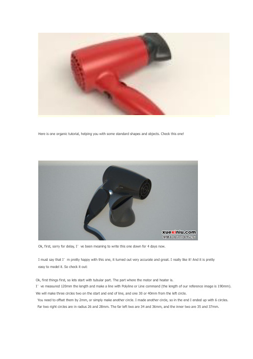
Here is one organic tutorial, helping you with some standard shapes and objects. Check this one!Ok, first, sorry for delay, I’ve been meaning to write this one down for 4 days now.I must say that I’m pretty happy with this one, it turned out very accurate and great. I really like it! And it is prettyeasy to model it. So check it out:Ok, first things first, so lets start with tubular part. The part where the motor and heater is.I’ve measured 120mm the length and make a line with Polyline or Line command (the length of our reference image is 190mm). We will make three circles two on the start and end of line, and one 30 or 40mm from the left circle.You need to offset them by 2mm, or simply make another circle. I made another circle, so in the end I ended up with 6 circles. Far two right circles are in radius 26 and 28mm. The far left two are 34 and 36mm, and the inner two are 35 and 37mm.Using InterpCrv command make a line connecting three outer circles. (use Quad option in Osnap for easier snapping). Next, do the same step for 3 inner circles.Using Sweep2 for first and second rail select outer two circles, and for cross section curve select Curve we made earlier. Make an ellipse and position it like on the image below:Next, from Front viewport use Project command to project that ellipse onto our tubular surface. You will get two curves on the surface, and we need only the front one. Using it, we will trim the surface and make a hole:Now, we’ll move onto handle. I like jumping from one part to another, I guess you already found that outFrom top viewport using reference image, outline outer edges with InterpCrv. Just to make sure, I made a straight horizontal linein Top viewport (using Ortho) and trimmed off the two curves. Now, we are sure those two curves has endings in the same cplane.Create another ellipse, this time one radius 15mm and other 13mm. Using End and Quad options in Osnap, position the ellipsebetween two curves, first move it to the end of one curve, and using PointsOn command, stretch the ellipse to fit the other curve’s end.Copy that ellipse, and position it like on the image below. You also need to stretch it with moving control points so it touches both curves.I have also made this ellipse 4 points higher. So, select upper three control points and move them 4 units up,and then move lower three control points and move them by 4 units (mm) down.Next, using that second bigger ellipsoid and two handle curves, we will make a sweep2.Using DupBorder we will duplicate border of newly created surface. We will get two closed curves, and we need the little one only, as we already have the bigger one. So, now, delete the surface, and again create sweep2 rail between two rail curves,and using now three closed curves:And now, we have a handle! Next, we will blend the two surfaces, so use BlendSrf command. Note that we need to check the Same height shapes option:Hopefully you got something like on the image below:Now, lets cap the tubular part.From the end of the first Line we created in this tutorial, create another line, and make it 10units (mm) long.Now, using Quad option in Osnap create InterpCrv (Curve: Interpolated Points) between two Quad points as start and end, and in the middle top of the 10mm long line:Trim one half of the newly created curve (arch) with 10mm long line, and that half arch needs to be revolved.I used Sweep1 and followed outer circle. But before that, we need to offset that half arch,and we need to move the inner circle by 2mm right from Top viewport(2mm will be the thickness of our shell - yeah, we still need to do that manually ).Now, we can use Sweep1 and make two surfaces:Ok, now, we will make little holes on the rear. From Right viewport make an ellipse 5×2.5mm. Rotate it for 45 degrees, and position like on the image:Using ArrayPolar make an array of 24 holes. Naturally the center would be the same center of circular surfaces.Next, using Copy and Paste duplicate those 24 ellipses, and using Scale shrink them,so you have 5 rows of 24 ellipses each row smaller than the previous.I have grouped each row of ellipses, and will extrude them one group at the time so I have more control, and less mess. So, extrude the ellipses and trim with two circular surfaces:Now, we will make just the same handle and tubular surface, but 2mm smaller.Using all those smaller circles, and smaller curves, we will make inner side of our dryer.You could use offset, but when using it curves are often made out of too much control points,and therefore your surfaces end up with much more isoparms, and we want our models cleaner.You could use Rebuild to make curves better, but then you might loose the original position of your curves. It is a bit tricky, and recreating all the curves, but 2mm smaller is a lot better way.Now, we need to blend the inner and outer surface where the air blows out.Next, on the part where the air is sucked in, using FilletEdge and 2mm as radius round that edge:Lets get back to our first 120mm long line. On the other end (the end there the air blows out from the dryer) create another circle with radius of 6.5mm. The second one from the same center but with 8mm as radius, and another one with radius of 10mm, then one with 16, and one with 18mm radius.Extrude those 5 circles by -15mm (minus is because we need it to go left when looking at it from Top viewport). Do not use Cap option.Next, you will blendsrf paired circles.The one in the middle, the smallest circle, using Arc command we will make an arc like on the image below:Using sweep1 command make a cap:Using Line or Polyline mimic the image below. I first created one line through the center,and then copied it and rotated by 90 degrees, next, I copied those two and rotated by 45 degrees. Next, each line I offset by 1mm up and down, and deleted the middle line.I have also offset the outer circle by 2mm, and aligned everything in the same cplane.And for the end of this part we will extrude those curves by 5mm with Cap option set to yesNow, lets make a little hole in the handle. For hanging the dryer on the wall or something. Create a closed curve like on the image below and trim what is inside:We will make three cross section curves, actually two lines, and one curve and using Sweep2 make a surface: (don’t forget to use Closed sweep option)Join that surface with handle surface, and fillet the two edges with 0.5mm radius:Next, lets create a curve for splitting the handle:Offset that curve by 0.3mm, and trim off what is between two curves:Now we need to blend the inner and outer shell surface (for both sides same settings):hair_dryer_41.jpg(67 KB, 下载次数: 21)STEP 4In this step we will be dealing with dryer cap that concentrates the hot air direction. We will use outer circle of right side of our tubular part:This circle needs to be offset by 4mm to the inside. From the center of this circle start a line 35mm long:Again, using InterpCrv make a curve starting from one Quad point on outer circle,middle of it is in the end of line, and the end of this curve is in the opposite Quad point.From the end and start make two lines. Having Ortho set to on helps!hair_dryer_45.jpg(22 KB, 下载次数: 16)Now, using Match, match the curve to both lines, and set the Continuity and Preserve other end to Tangency. hair_dryer_46.jpg(46 KB, 下载次数: 20)(Note: if you want to match the one end of a curve to the line, then you need to first click near the one end on the curve, then on the line) Using the line that is in the center (you might need to move it to the right a little - just so it crosses your curve (arch)) trim the curve.Use Sweep1 to rail revolve and make a cap.hair_dryer_48.jpg(21 KB, 下载次数: 13)Next, make an ellipse. First end of axis is at 77m, and second at 22mm.(select Diameter from command options selection). And then make another ellipse,again use Diameter, and set 48×14mm. Position both centres of these two ellipses in the same point.hair_dryer_49.jpg(36 KB, 下载次数: 15)I have positioned the both centres of two ellipses to the center of our cap, and then I moved it to the right a little:Now, move the inner ellipse for 42mm to the inside:hair_dryer_51.jpg(27 KB, 下载次数: 14)Using InterpCrv, create a curve between two coplanar Quad points on two ellipses. Now it seems like it is a line,but if you turn on the control points you will get two more cpoints in side this so called line, select two and move outside a little:Using Sweep2 use two ellipses as rail curves, and one connecting curve as cross section. hair_dryer_53.jpg(30 KB, 下载次数: 18)Trim the parts we don’t need:Now, we will make a fillet between these two surfaces… First I joined these two as I wanted to make a FilletEdge, but that didn’t turn out good, so I Exploded the mesh, and made a FilletSrf between these two surfaces.The radius was 10mm and everything went well. If you encounter problems with both FilletEdge and FilletSrf,try reducing od increasing the radius, and if that doesn’t work either, then try the pipe method.hair_dryer_55.jpg(28 KB, 下载次数: 15)Now, using the same exact method we did before for shelling, we will make a shell for this dryer part.Then, we will make one big circle from the center of our little part:hair_dryer_56.jpg(63 KB, 下载次数: 20)Still in the top viewport, we will Trim off the cap, so we get that round edge and BlendSrf the edges(you can either try JoinEdge command to join broken edges, or you can blend 4 time, and then join everything):Now, on the back of this part, make a cross section curve like on the image below: Use polyline hair_dryer_58.jpg(38 KB, 下载次数: 19)And using Sweep2, make a surface:Then, you can fillet the edges.hair_dryer_60.jpg(74 KB, 下载次数: 15)STEP 5Start with ellipse in Right viewport. (Click on diameter option) and input for end of first axis 32mm, and for end of second axis 16mm.Now, using Rectangle (select Rounded option) make a rectangle (first length 20mm, and second 13mm, and center it in the center of our ellipse: hair_dryer_62.jpg(42 KB, 下载次数: 16)Rotate the two curves from top viewport, and extrude with no other extrusion options: hair_dryer_63.jpg(87 KB, 下载次数: 17)Trim the inner part of outer shell of our dryer with extruded ellipse, and split the inner shell of dryer with extruded rounded rectangle:Loft the edges:hair_dryer_65.jpg(34 KB, 下载次数: 16)Fillet the Edge with 1mm radius.Now, create this little rounded rectangle, and position it like on the image:hair_dryer_67.jpg(21 KB, 下载次数: 15)Project it on the blue surface, and extrude that projected curve by 3mm (-3mm) and make a cap with Patch command. hair_dryer_68.jpg(26 KB, 下载次数: 16)STEP 6And for the end, we will make another button. The first one was for controlling the fan speed, and this one is On/Off button. So, create an Ellipsoidhair_dryer_69.jpg(73 KB, 下载次数: 19)Offset that ellipsoid with OffsetSrf command by 0.5mm towards outside. With the bigger ellipsoid trim the handle:Fillet the edges with 0.4mm, and you’re donehair_dryer_71.jpg(89 KB, 下载次数: 19)。
犀牛建模技巧6之(Rhino倒角全析)

我们来看看犀牛建模到底有哪些技巧6(Rhino倒角全析)序言:作为2013年的第一篇帖子,首先祝大家新年快乐,财源广进。
也希望大家在年乐的时候不要忘记照顾一下犀牛先生哦。
多看、多练、多想永远是学好软件的必经之路,犀牛也不例外。
(红色字体要多去理解)这里我们重点讲解建模过程中遇到的各种倒角问题。
犀牛里面的倒角工具我们也很熟悉,体倒角工具、面倒角工具等。
其实我希望大家重点掌握的不是以上两种直接倒角工具。
我希望你们重点掌握如何利用犀牛工具绘制圆角,讲解时会涉及到曲率和辅助面等。
那么为什么要重点掌握这个,其实这是对模型的一个挑战,也是对模型质量的严格要求。
我们在绘制一些几何体造型的时候,体倒角和面倒角工具用的相对较多,前面我在讲解几何体造型的时候提到过这个问题。
讲解前我需要提出这么一个问题,如果出现多曲面无缝衔接,多曲面集点等情况,我们该如何处理倒角呢。
我们一起来探讨下这个问题。
因为这里是对Rhino倒角的全面讲解,我首先讲解一下体倒角和面倒角遇到的难题,很多人在建模过程中一遇到倒角就很头疼,所以干脆不倒角,这时模型就会出现很多尖锐的边缘,这会导致模型质量下降和渲染时环境反射渡面等各种问题。
所以态度一定要端正。
直接倒角工具需要注意三个方面的问题,一是整体倒角(又称相关倒角)、二是倒角大小及先后顺序、三是辅助面倒角。
这三个问题是我们在建模过程中最常见的。
1、整体倒角有助于我们衔接相关面,过渡相关角。
如图1多面集点体进行单个边缘倒角如图2我们发现其余多个边缘无法衔接第一个圆角如图3这就是我们常说的破角。
解决这个问题一定要熟练掌握整体倒角的建模技巧。
如图4整体倒角其实比较简单,也是最基本的倒角技巧,这里不做重点解析。
希望大家在建模过程中要有实体概念,要有整体倒角概念。
(为什么我再次强调实体化,它是整体倒角最能突出效果的载体)。
2、倒角大小及先后顺序(这里不以集体倒角为基础讲解,因为集体倒角不会出现太多的问题,软件会自动匹配。
Rhino教程:用Rhino制作一把螺丝刀

Rhino教程:用Rhino制作一把螺丝刀关键词:Rhino教程:用Rhino制作一把螺丝刀用Rhino制作一把螺丝刀这是一个Rhino 建摸的基础教程。
面向初学者,通过简单模型的制作,了解Rhino的基本建模方法。
这个练习使用最新Rhino 2.0 版,由于并没有使用到它的新功能,在1.1 版本下(包括试用版)同样可以完成这个练习。
大家都知道Rhino的功能按钮数量庞大而繁杂,在练习中涉及的按钮,会尽量给出它的菜单选择位置。
这样,对Rhino 不太熟悉的人不至于因寻找按钮而中断练习。
首先打开Rhino 或建立一个新的工作区。
使用控制点曲线工具(Curve > Free-From > Control Points)在 Top 视图用鼠标绘制螺丝刀把手的剖面曲线,如下图:如果需要对曲线进行修改,可以使用(Edit > Edit Point > Control Points On)打开曲线的控制点显示,用鼠标拖动控制点对曲线的曲率进行修改,尽量使最下端的一点处在Top 视图的X轴上(见下图)。
完成后,用鼠标右键点击该按钮可以关闭控制点显示。
螺丝刀的把手剖面曲线修改完成后,就可以用 Rhino的旋转成面的工具生成模型。
首先点击状态栏的 Snap打开捕捉到网格功能。
使用旋转成面工具 (Surface > Rev olve ),点击上面的曲线后按鼠标右键,在Top 视图沿着红色的X 轴的水平方向为它指定旋转轴,这时会弹出一个旋转参数设置窗口:认可缺省的参数并确认。
手柄的模型就形成了。
可以用按钮(Render > Shade)在透视图预览;也可以使用(Render > Render )渲染视图查看结果。
为了便于以后的操作,先关闭捕捉到网格(Snap )功能。
接下来用同样的方法制作把手与头部的金属结合部分。
绘制并编辑曲线(下左图);打开 Snap ,旋转成型(下右图)。
Rhino犀牛软件使用手册
Rhino犀牛软件使用手册NURBSmodelingforWindow4.0使用手册Copyright©1993-2006RobertMcNeel&Aociate.Allrightreerved.PrintedinU.S.A.所有其它品牌或产品名称是其个别所有权者的注册商标或商标。
目录目录NURBS建模............................................................. (7)作业视窗............................................................. (8)作业视窗菜单............................................................. (8)作业视窗显示模式............................................................. (8)鼠标巡览............................................................. .. (9)作业视窗投影............................................................. (9)建模辅助............................................................. . (11)十字光标、标记及轨迹线............................................................. .. (11)锁定格点............................................................. (11)正交模式............................................................. (11)距离限制............................................................. (12)角度限制............................................................. (12)垂直模式............................................................. (12)坐标系统............................................................. . (14)笛卡儿坐标............................................................. (14)世界坐标............................................................. (14)工作平面坐标............................................................. . (14)相对坐标............................................................. (15)物件锁点............................................................. . (17)持续性物件锁点............................................................. . (17)智慧轨迹............................................................. (18)点物件............................................................. (19)曲线............................................................. (19)曲面.............................................................. .. (20)多重曲面............................................................. (22)实体............................................................. (22)网格物件............................................................. (23)目录编辑曲线与曲面............................................................. . (24)组合............................................................. (24)炸开............................................................. (24)修剪与分割............................................................. (24)控制点编辑............................................................. (24)数............................................................. . (25)变动............................................................. (26)移动............................................................. (26)复制............................................................. (26)旋转............................................................. (26)缩放............................................................. (26)镜像............................................................. (26)定位............................................................. (26)阵列............................................................. (26)析............................................................. . (27)测量距离、角度及半径............................................................. . (27)曲线与曲面的方向............................................................. . (27)曲率............................................................. (27)以视觉分析曲面............................................................. . (28)显示边缘............................................................. (29)检测.............................................................. .. (30)组织模型............................................................. . (31)图层............................................................. (31)组............................................................. (31)图块............................................................. (32)分工作业............................................................. (32)批注............................................................. (33)尺寸标注............................................................. (33)文字............................................................. (33)标注引线............................................................. (34)目录批注点............................................................. (34)移除隐藏线............................................................. (34)注............................................................. (34)渲染............................................................. (35)灯光............................................................. (35)渲染网格............................................................. (35)教学:实体与变动............................................................. .. (36)输入坐标............................................................. (36)建立玩具拖车的主体............................................................. . (36)建立轮轴与轮框............................................................. . (38)建立螺丝帽............................................................. (38)设定颜色.............................................................. .. (40)数组螺丝帽............................................................. (41)建立轮胎............................................................. (41)镜像轮子............................................................. (42)建立眼睛............................................................. (43)建立拉绳............................................................. (44)教学:旋转曲线建立曲面............................................................. .. (48)建立自由造型的手电筒模型............................................................. .. (48)设定模型............................................................. (48)建立一条中心线............................................................. . (49)建立主体的轮廓曲线............................................................. . (49)建立镜片的轮廓曲线.............................................................. (50)建立手电筒主体............................................................. . (51)建立镜片............................................................. (52)设定物件属性及渲染............................................................. . (52)教学:扫掠、放样、挤出............................................................. .. (53)建立耳罩外壳............................................................. . (53)挤出曲线成为实体............................................................. . (54)将曲面组合在一起............................................................. . (56)目录建立耳罩的软垫............................................................. . (56)建立支架............................................................. (57)建立头带.............................................................. .. (60)建立耳机线............................................................. (64)镜像耳机的组件............................................................. . (65)教学:控制点编辑与混接曲面............................................................. (68)建立身体与头部............................................................. . (68)建立与放置眼睛............................................................. . (71)建立嘴部............................................................. (73)建立双脚............................................................. (74)建立尾巴............................................................. (77)建立翅膀............................................................. (79)最后修饰............................................................. (81)设定渲染材质............................................................. . (82)教学:放样船壳............................................................. . (83)建立船壳曲线............................................................. . (84)检查整平度............................................................. (84)建立3D曲线............................................................. . (85)关于曲线............................................................. (86)放样船壳曲面............................................................. . (87)修剪船头与船底............................................................. . (88)建立尾舷板............................................................. (89)完成尾舷板............................................................. (92)建立甲板............................................................. (92)教学:描绘背景图............................................................. .. (95)建立身体............................................................. (95)建立头部............................................................. (98)混接头部与身体............................................................. . (99)建立眼睛.............................................................. (100)建立尾部............................................................. . (101)目录描绘翅膀与脚............................................................. .. (101)教学:将曲线包覆至曲面上............................................................. . (103)建立一个曲面............................................................. .. (103)建立将被包覆至曲面上的物件 (104)控制物件包覆至目标曲面的位置 (104)教学:混接与修剪............................................................. (107)建立机身............................................................. . (109)在机身前、后建立混接曲面............................................................. (111)在机身修剪出观景窗的缺口............................................................. (114)建立观景窗............................................................. . (116)混接机身与观景窗............................................................. .. (118)建立机身底面............................................................. .. (119)建立镜头并与机身混接............................................................. .. (122)更多的说明............................................................. .. (124)网络上的说明............................................................. .. (124)索引............................................................. . (125)NURBS建模NURBS建模NURBS(Non-UniformRationalB-Spline,非均匀有理B样条曲线)是一种可做为任何造型建模的数学表现方式--从简单2D的直线、圆、圆弧、立方体至最复杂3D的自由造型曲面或实体。
- 1、下载文档前请自行甄别文档内容的完整性,平台不提供额外的编辑、内容补充、找答案等附加服务。
- 2、"仅部分预览"的文档,不可在线预览部分如存在完整性等问题,可反馈申请退款(可完整预览的文档不适用该条件!)。
- 3、如文档侵犯您的权益,请联系客服反馈,我们会尽快为您处理(人工客服工作时间:9:00-18:30)。
Rhino(犀牛)螺纹灯泡建模教程
1〉画好轮廓线和轴线(PS下图的那个螺旋线是我量距离画的,不用在放样中
2〉画一个单列的螺旋线,将螺旋线开始端的轮廓线镜像一个到对面,调整位置使螺旋线经过轮廓线的中点,这样做的目的是让最后放样出来的轨道的边缘保持在水平位置
3〉单轨放样,结果如下
4〉平移复制5个并且将它们组合在一起
5〉画两条辅助线,剪切轨道模型
6〉在剪切好的轨道模型下端,画出一个圆环,便于曲面混接
7〉执行混接命令,结果如下
8〉选择轨道模型上端的黄色轮廓线执行旋转命令
9〉结果如下
10〉将这段曲面与轨道模型上端进行混接
11〉选择轨道模型下端的黄色轮廓线同样执行旋转命令
12〉结果如下
13〉接下来选择灯泡的轮廓线,执行旋转命令
14〉结果如下
15〉删除无用的线条,封闭曲面,准备进行渲染
16〉制作一个自发光材质和金属材质,分别添加给灯泡和下端的螺纹模型
17〉大功告成,一个灯泡模型和效果图就完成啦!。