水质PH数字传感器说明书
海尔科技的pH电导性传感器说明书

Sensor FeaturesSensor housings are constructed of PEEK,a high performance thermoplastic that provides outstanding mechanical strength and chemical resistance. Multiple sealing materials are used to preserve sensor integrity over a wide range of applications.A large volume, dual junction saltbridge is used to maximize the in-service time of the sensor. The annular junction provides a large surface area to minimize the chance of fouling. Large electrolyte volume and dual reference junction minimizes contamination of the reference solution. The replaceable saltbridge allows for easy sensor regeneration.The reference element of this sensoris a second pH electrode immersed ina reference buffer solution. This glass reference system allows the sensorto be used in applications that poison conventional pH sensors.An integral preamplifier is encapsulatedin the body of the sensor. This creates a low impedance signal output which ensures stable readings in harsh environments, and maximize the distance between sensor and transmitter. Sensor diagnostics are used to alarm the user in the event of electrode breakage, lossof sensor seal integrity, or integral temperature sensor failure.Sensor electrodes can be user-specifiedto ensure measurement reliability and maximum sensor lifetime. The type of glass used in the pH electrode can be selected foroptimal performance. The metal electrode used for ORP measurements can be platinum or gold, depending on chemical makeupof the process solution.PHTX-45, transmittershown with PHE-45Pelectrode, both shownsmaller than actual size.Ordering Example:PHTX-45, pH transmitter, PHE-45P, electrode and PHA-4, buffer solution.SIMULATION features provide the user with complete control of the system output under any condition.Diagnostic messages provide a clear description of system condition, which eliminatesconfusing error codes that must be looked up in the operator’s manual.The flexible two-point and sample calibration options include auto-buffer recognition from thirteen built-inbuffer tables. Manual override of the automatic buffer values allows the user to customize calibration values. To ensure high accuracy, all calibration methods include stability monitors that check temperature and main parameter stability before accepting data.SpecificationsPHE-45P and ORE-45P Sensor SpecificationsSensor Cable: 3 m (10’) Measuring Range:PHE-45P: 0 to 14.00 pH ORE-45P: -1000 to 2000 mVSensitivity: 0.002 pH, 0.2 mV (ORP)Stability: 0.02 pH or 2 mV per 24 hours, non-cumulative Wetted Materials:PHE-45P: PEEK, ceramic, titanium, glass, FKM, EDPM (316 stainless steel with 316SS body option)ORE-45P: PEEK, ceramic, titanium, glass, FKM, EDPM, platinum or gold Temperature Compensation: Pt1000 Sensor Cable: 6 Conductor plus 2 shields Temperature Range: -5 to 95°C (23 to 203°F)Pressure Range: 0 to 100 psig Maximum Flow Rate: 3 m (10’) per secondSensor to Transmitter Distance: 914 m (3000’)Mounting Options: 1 NPT convertible Weight/Shipping Weight: 0.45 kg (1 lb)P HTX-45 Transmitter SpecificationsEnclosure: NEMA 4X, IP65,polycarbonate, stainless steel hardware, weatherproof and corrosion resistant, 112 H x 112 W x 89 mm D (4.4 x 4.4 x 3.5”)Mounting Options: Wall, panel, pipe, Din rail, integral-sensorConduit Openings: 2-PG9 openings, 1 to 1 NPT center opening, cord grips and plug includedWeight/Shipping Weight: 0.45 kg (1 lb)Display: Large, high-contrast,super-Twist (STN) LCD; 4-digit main display with 19.1 mm (0.75”) seven-segment character, 12-digit secondary display,7.6 mm (0.3”) 5 x 7 dot matrix character Keypad: 4-key membrane type with tactile feedback, polycarbonate with UV coating, integral EMI/static shield and conductivity coated window Ambient Temperature:Service: -20 to 60°C (-4 to 140°F) Storage: -30 to 70°C (-22 to 158°F)Ambient Humidity:0 to 95%, non-condensingLocation: Designed for hazardous and non-hazardous areasEMI/RFI Influence: Designed to EN61326-1Voltage Range:16 to 35 Vdc (two-wire device)Output Isolation: 600 V galvanic isolation Transmitter Cable Type: Belden twisted-pair, shieldedFilter: Adjustable 1 to 99 seconds additional damping to 90% step input Temperature Input: Selectable Pt1000 or Pt100, automatic compensationPHE-45P Performance SpecificationsDisplayed Parameters: Main Input: 0 to 14.00 pH; Sensor Voltage: ±500 mV; Loop Current: 4 to 20 mA; Sensor Temperature: -10 to 110°C (14 to 230° F)Main Parameter Range: 0 to 14.00 pH Input Impedance: Greater than 1013 ΩRepeatability: 0.1% of or better Sensitivity : 0.05% of span Non-Linearity: 0.1% of span Stability: 0.1% of spanper 24 hours, non-cumulative Warm-Up Time: 4 seconds to rated performanceSupply Voltage Effects: ±0.05% span Transmitter Response Time: 4 seconds to 90% of step input at lowest settingTemperature Drift:Span or zero, 0.02% of span/°C Sensor to Transmitter Distance: 914 m (3000’) w/preamp, 9.1 m (30’) w/o preamp。
水质PH值传感器(RA0708_R72608_RA0708Y)使用说明书
水质PH值传感器(RA0708_R72608_RA0708Y)使用说明书水质PH值传感器说明书——适用型号:RA0708;RA0708Y;R72608Copyright©Netvox Technology Co.,Ltd.This document contains proprietary technical information which is the property of NETVOX Technology.It shall be maintained in strict confidence and shall not be disclosed to other parties,in whole or in part,without written permission of NETVOX Technology.The specifications are subject to change without prior notice.目录一、声明 (2)二、实物外观 (2)三、简介 (2)四、产品特性 (2)五、操作说明 (2)六、安装方法 (4)七、维护与保养 (6)一、声明在未经大洋事先书面许可的情况下,严禁以任何形式复制、传递、分发和存储本文档中的任何内容。
大洋遵循持续发展的策略。
因此,大洋保留在不预先通知的情况下,对本文档中描述的任何产品进行修改和改进的权利。
在任何情况下,大洋均不对任何数据或收入方面的损失,或任何特殊、偶然、附带或间接损失承担责任,无论该损失由何种原因引起。
本文档的内容按“现状”提供。
除非适用的法律另有规定,否则不对本文档的准确性、可靠性和内容做出任何类型的、明确或默许的保证,其中包括但不限于对适销性和对具体用途的适用性的保证。
大洋保留在不预先通知的情况下随时修订或收回本文档的权利。
二、实物外观图一RA0708外接PH 值Sensor(以实物为准)三、简介RA0708_R72608_RA0708Y 为netvox 基于LoRaWAN 开放协议的ClassA 类型设备,兼容LoRaWAN 协议。
ph说明书
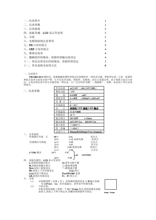
一、仪表简介 ........................................................................................ 1 二、仪表参数 ........................................................................................ 1 三、仪表接线 ........................................................................................ 2 四、面板各键、LCD 显示符说明 ......................................................... 2 五、安装 ................................................................................................ 2 六、电极线接线注意事项 ..................................................................... 3 七、PH 计如何校正 .............................................................................. 3 八、ORP 计如何校正 ............................................................................ 4 九、维修及保养 .................................................................................... 4 十、酸碱度控制器高、低限控制输出值设定 ....................................... 4 十一、氧化还原电位控制器高、低限控制设定 ................................... 5 十二、常见故障及处理方法 .. (6)一、仪表简介PH/ORP-6658测控仪,是集酸碱度测控和氧化还原测控於一体的多功能、智能型仪表。
S-PH-01 pH 传感器用户指南说明书

User GuidepH Sensor(S-pH-01)User GuideVersion:V2.11/20©2008-2021Seeed Technology Co.,Ltd.All rights reserved.Content1.Introduction (3)2.Wiring diagrams (4)3.Dimension (5)4.Installation Maintenance and Calibration (6)4.1Installation (6)4.2Maintenance (6)5.Output Signal Conversion (7)6.RS485Modbus Protocol (8)6.1Modbus Protocol (8)6.2Modbus Register (9)6.3Modbus Register Detail Description (12)7.Software Configuration Utility (20)1.IntroductionS-PH-01transmitter measures the PH of solution or semi-solid substrate.The output signal can be RS485and Analog Voltage.The sensor is applicable for industrial,water processing,sewerage system,irrigation,smart agriculture etc.■Can be used for PH measurement ■Output Interface with RS485,Voltage ■High impedance and isolated electrode input ■High accuracy with excellent stability■Reverse power protection and Built-in TVS/ESD protectionSpecificationsOutput Interface Analog Voltage 0-2V(Output resistance ~0ohm)RS485Modbus-RTU Power Supply 3.9-30V/DC 3.9-30V/DC Power Consumption 35mA@24V DC 35mA@24V DCStart-up time <2secondsPH Measurement High impedance and isolated input;Range:0-14PH,Resolution:0.01PH,Accuracy:+/-0.1PH;Can be used for solution or semi-solid substrate Temperature Measurement (Option)Range:-40~80°C,Resolution:0.1°C,Accuracy:+/-0.5°C IP Ratings Electrode:IP68;Transmitter:IP65Operating Temperature -40~85°CInstallationElectrode:3/4"NPT screw threads;Transmitter:Mounting holeCable Length Power and Signal Cable:2meters or Customize;Electrode Cable:5mete rsDimensionElectrode:Width*Diameter 160*30mm;3/4"NPT screw threads Transmitter:140mm*65mm*50mm2.Wiring diagramsType Wiring diagram Analo gVoltag eOutpu tRed (V+):Power Supply +Black (G):Power Supply -Blue (O1):Analog OutputRS485ModbusRed (V+):Power Supply +Black (G):Power Supply -Yellow (T+):RS485+/A/T+White (T-):RS485-/B/T-3.DimensionElectrode DimensionTransmitter Dimension*Note:Do not put the Transmitter into the liquid.4.Installation Maintenance and Calibration4.1InstallationInstallation locations of Electrodes will vary depending on the system design.The key is to monitor a good representative sample of the whole solution directly after introduction of chlorine.The installation location must allow for complete contact of the scrubber liquid with the probes.Some example installation locations for Electrodes include the following:■Outlet of packed tower■Outlet of recycle pump■Pump bypass line■Heat Exchanger bypass line4.2MaintenanceUnder normal conditions,electrodes can last anywhere from several months to several years depending on the type of operation,rate of production,strength of product,and quality of the raw materials used in the process.Because each application is different,there is no average life expectancy.Because the pH responsive glass bulb or flat surface is relatively thin,care should be taken so that the bulb does not become scratched or broken.It is also important that ORP measuring surfaces are not scratched or gouged.The suggestions in this sheet are intended to help avoid these problems.Coating of an electrode’s measuring surface can lead to erroneous readings including shortened span and slow response times.The type of coating determines the type of cleaning technique.Soft Coatings can be removed by vigorous stirring,by use of a squirt bottle or,very carefully,by gently wiping with a soft,clean non-abrasive paper or cloth.Hard Coatings should be chemically removed.The chemical used to remove the coating should be the least harsh chemical that dissolves the coating in1or2minutes and does not attack the electrode’s materials of construction.For example,a calcium carbonate coating might be removed with5%HCl(muriatic acid).Oily or Organic Coatings are best removed with detergents or an appropriate solvent that does not attack the electrode’s materials of construction.For example,isopropyl alcohol might be used but acetone should be avoided if the electrode’s body is made of CPVC.5.Output Signal ConversionPH output conversionOutput Interface Parameters Range Conversion FormulaAnalog Voltage Output0-2V PH range:0-14PH PH=7.00*VOLTAGE.When VOLTAGE=1.0V,thenPH=7.00*1.00=7.RS485 Modbus-RTU PH range:0-14PH PH=(REGISTER VALUE)/100.When REGISTERVALUE=7000,then PH=7000/100=7.00. Temperature range:-40-80°C TEMPERATURE=(REGISTERVALUE)/100.WhenREGISTER VALUE=2013,then TEMPERATURE=2013/100=20.13°C.NOTE:The unit of VOLTAGE is(V)6.RS485Modbus Protocol6.1Modbus ProtocolModbus Protocol is widely used to establish master-slave communication between intelligent devices or sensors.A MODBUS message sent from a master to a slave contains the address of the slave,the function code(e.g.'read register'or'write register'),the data,and a check sum(LRC or CRC).The sensor is RS485interface with Modbus protocol.The default serial communication settings is slave address1,modbus rtu,9600bps,8databits and1stop bit.All communication settings can be changed with modbus command,and take effective after re-power up the sensor.Following modbus function code are supported by sensor.Modbus Function Code0x03:used for reading holdingregister.Modbus Function Code0x04:used for readinginput register.Modbus Function Code0x06:used for writing single holding register.Modbus Function Code0x10:used for writing multiple holdingregister.6.2Modbus RegisterParameters RegisterAddr.(HEX/DEC)DataTypeModbusFunctionCode(DEC)Range and Comments DefaultValueTEMPRATURE0x0000/0INT16RO 3/4-4000-8000for-40.00~80.00°C.N/APH PHVALUE 0x0001/1UINT16RO3/40-1400for0.00-14.00N/ATEMPCOMPENSA TEE N 0x0020/32UINT16R/W3/6/160:ExternalTemperature sensor1:Disabled2:On boardtemperature sensor1PHCALIBRAWAD0 PH calibration point for PH=4.010x0030/48UINT16R/W3/6/16-2000~2000for-2000~2000;Write0xFFFF tocalibrate.N/APHCALIBRAWAD1 PH calibration point for PH=7.000x0031/49UINT16R/W3/6/16-2000~2000for-2000~2000;Write0xFFFF tocalibrate.N/APHCALIBRAWAD2 PH calibration point forPH=10.010x0032/50UINT16R/W3/6/16-2000~2000for-2000~2000;Write0xFFFF tocalibrate.N/ASLAVEADDRESS0x0200/512UINT16R/W3/6/160-2551or12BAUDRATE0x0201/513UINT16R/W 3/6/160-60:1200bps1:2400bps2:4800bps3:9600bps4:19200bps5:38400bps3:9600bpsPROTOCOL0x0202/514UINT16R/W 3/6/160-10:Modbus RTU0:Modbus RTUPARITY0x0203/515UINT16R/W 3/6/160-20:None1:Even2:Odd0:NoneParityDATABITS0x0204/516UINT163/6/1611:8databitsR/W1:8databits STOPBITS 0x0205/517UINT16R/W 3/6/160-10:1stopbit 1:2stopbits0:1stopbitRESPONSEDELAY 0x0206/518UINT16R/W 3/6/160-255for 0-2550milliseconds 0ACTIVEOUTPUTINTE R VAL0x0207/519UINT16R/W3/6/160-255for 0-255seconds.NOTE:UINT16:16bit unsigned integer,INT16:16bit signed integer NOTE:RO:Register is Read Only,R/W:Register is Read/Write NOTE:HEX is Hexadecimal (data with 0x/0X prefix),DEC is Decimal6.3Modbus Register Detail DescriptionTEMPERATURE Data Range-4000-8000For -40.00~80.00°CDefault:N/APower Down Save N/ANote:Temperature value (Binary complement).Example:When REGISTER =0x0702(HEX format),thenVALUE=(0x07*256+0x02)/100=17.94°C.When REGISTER=FF05H (HEX format),then VALUE=((0xFF*256+0x05)-0xFFFF-0x01)/100=(0xFF05-0xFFFF-0x01)/100=-2.51°C.PH VALUE Data Range0-1400for 0-14.00PHDefault:N/APower Down Save N/ANote:PH valueExample:When REGISTER =0x02BC (HEX format),then VALUE=(0x02*256+0xBC)/100=7.00PHTEMPCOMPENSATEEN Data Range0:External Temperature sensor 1:Disabled2:On board temperature sensorDefault:1Power Down Save YESNote:Temperature compensationPHCALIBRAWAD0Data Range-2000~2000Default:N/APower Down Save YESNote:PH calibration AD value for PH=4.01;Immerse the electrode into PH=4.01solution and wait until the reading value being stable,then write 0xFFFF to this register to calibrate.PHCALIBRAWAD1Data Range-2000~2000Default:N/APower Down Save YESNote:PH calibration AD value for PH=7.00;Immerse the electrode into PH=7.00solution and wait until the reading value being stable,then write 0xFFFF to this register to calibrate.Data Range-2000~2000Default:N/APower Down Save YESNote:PH calibration AD value for PH=10.01;Immerse the electrode into PH=10.01solution and wait until the reading value being stable,then write 0xFFFF to this register to calibrate.SLAVEADDRESS ---Modbus Slave Address Data Range0-255Default:1or 12Power Down Save YESNote:Please re-power on the sensor to take effective after set.BAUDRATE ---Serial Comm Baudrate Data Range0-50:1200bps 1:2400bps 2:4800bps 3:9600bps 4:19200bp s5:38400bpsDefault:3Power Down Save YESPROTOCOL ---Serial Comm Protocol Data Range0:Modbus RTUDefault:0Power Down Save YESNote:Please re-power on the sensor to take effective after set.PARITY ---Serial Comm Parity Data Range0-20:NONE 1:EVEN 2:ODDDefault:0Power Down Save YESNote:Please re-power on the sensor to take effective after set.DATABITS ---Serial Comm Databits Data Range11:8databitsDefault:1Power Down Save YESNote:Please re-power on the sensor to take effective after set.STOPBITS ---Serial Comm Stopbits Data Range0-10:1stopbit 1:2stopbitsDefault:0Power Down Save YESNote:Please re-power on the sensor to take effective after set.RESPONSEDELAY ---Serial Comm Response Delay Data Range0-255for 0-2550milliseconds,0for disabledDefault:0Power Down Save YESNote:Sensor will delay a period before response to master request command.Example:When set to 5and receive a request from master device,then sensor will delay 5*10ms=50ms,then response to master.ACTIVEOUTPUTINTERVAL ---Serial Comm Active Output Interval time Data Range0-255for 0-255seconds,0for disabledDefault:0Power Down Save YESNote:Please re-power on the sensor to take effective after set.Note:Sensor will output thedata actively without any master request command.Note:Only ONE sensor should be on RS485network,or there will be data collision and corrupt the data on line.Note:Use key button to restore the serial comm parameters factory value to exit the active output mode.Example:When set to 5then sensor will output the data every 5seconds without any master request command.6.4Modbus Function CodeFor description below,data started with 0X/0x means that it’s in HEX format.6.4.1Function Code 3Protocol ExampleMaster Request:AA 03RRRR NNNN CCCCAA 1byte Slave Address,0-2550x031byte Function Code 3RRRR 2byte Starting Register Addr NNNN 2byte Quantity of Register to read CCCC2byteCRC CHECKSUMSlave Response:AA 03MM VV0VV1VV2VV3…CCCCAA 1byte Slave Address,0-2550x031byte Function Code 3MM 1byte Register Data Byte Count VV0,VV12byte Register Value (High8bits first)VV2,VV32byte Register Value (High8bits first)……Register Value (High8bits first)CCCC2byteCRC CHECKSUMExample:Read register 0x0200-0x0201,that is slave address and baudrate.Master Request:010*********C5B3Slave Response:01030400010003EB F2Slave Addr.1byte0x01Slave Addr.1byte 0x01Function Code 1byte 0x03Starting Register Addr.2byte0x0200Quantity of Register to read 2byte0x0002Checksum2byte0xC5B3Function Code1byte0x03 Register Data ByteCount1byte0x04Register Value: Address 2byte0x00(HIGH8Bits)0x01(LOW8Bits)Register Value: Baudrate 2byte0x00(HIGH8Bits)0x03(LOW8Bits)Checksum2byte0xEBF26.4.2Function Code4Protocol Example Master Request:AA04RRRR NNNN CCCCAA1byte Slave Address,0-2550x041byte Function Code4RRRR2byte Starting Register AddrNNNN2byte Quantity of Register to readCCCC2byte CRC CHECKSUMSlave Response:AA04MM VV0VV1VV2VV3…CCCC AA1byte Slave Address,0-2550x041byte Function Code4MM1byte Register Data Byte CountVV0,VV12byte Register Value(High8bits first)VV2,VV32byte Register Value(High8bits first)……Register Value(High8bits first)CCCC2byte CRC CHECKSUM Example:Read register0x0000-0x0002,that is temperature,PH value.Master Request:01040000000271CBSlave Addr.1byte0x01Function Code1byte0x04Starting RegisterAddr.2byte0x0000Quantity ofRegisterto read2byte0x0002 Checksum2byte0x71CB Slave Response:01040408C3029E8910 Slave Addr.1byte0x01Function Code1byte0x04Register Data ByteCount1byte0x04Register Value: Temperature 2byte0x08(HIGH8Bits)0xC3(LOW8Bits)Register Value: PH 2byte0x02(HIGH8Bits)0x9E(LOW8Bits)Checksum2byte0x8910 Temperature=(0x08*256+0xC3)/100=2243/100=22.43°C PH=(0x02*256+0x9E)/100=670/100=6.70PH6.4.3Function Code6Protocol Example Master Request:AA06RRRR VVVV CCCCAA1byte Slave Address,0-2550x061byte Function Code6RRRR2byte Register Addr(High8bits first)VVVV2byte Register Value(High8bits first)CCCC2byte CRCCHECKSUMSlave Response:AA06RRRR VVVV CCCCAA1byte Slave Address,0-2550x061byte Function Code6RRRR2byte Register Addr(High8bits first)VVVV2byte Register Value(High8bits first)CCCC2byte CRC CHECKSUMExample:Write Register0x0020,that is set temperature compensationRequest:0106002000008800Slave Addr.1byte0x01Function Code1byte0x06Register Addr.2byte0x0020(High8bits first)Register Value2byte0x0000(High8bits first)Checksum2byte0x8800Response:0106002100011800Slave Addr.1byte0x01Function Code1byte0x06Register Addr.2byte0x0020(High8bits first)Register Value2byte0x0000(High8bits first)Checksum2byte0x88006.4.4Function Code16Protocol Example Master Request:AA10RRRR NNNN MM VVVV1VVVV2…CCCC AA1byte Slave Address,0-2550x101byte Function Code0x10RRRR2byte Starting Register AddrNNNN2byte Quantity of Register to writeMM1byte Register Data Byte CountVVVV12byte Register Value(High8bits first)VVVV22byte Register Value(High8bits first)……Register Value(High8bits first)CCCC2byte CRC CHECKSUMSlave Response:AA10RRRR NNNN CCCCAA1byte Slave Address,0-2550x101byte Function Code0x10RRRR2byte Starting Register AddrNNNN2byte Quantity of Register to writeCCCC2byte CRC CHECKSUMExample:Write Register 0x0200-0x0201,that is set slave address to 1,and baudrate to 19200bp.Master Request:0110020000020400010004BACCSalve Response:01100200000240700x011byte Slave Addr.0x10(HEX)1byte Function Code 0x100x02002byte Starting Register Addr(High8bits first)0x00022byte Quantity of Register to write(High8bits first)0x40702byteCRC CHECKSUM0x011byte Slave Addr.0x10(HEX)1byte Function Code 0x100x02002byte Starting Register Addr 0x00022byte Quantity of Register to write 0x041byte Register Data Byte Count 0x00012byte Register Value:Slave Address 10x00042byte Register Value:Baudrate 19200bps 0xBACC2byteCRC CHECKSUM7.Software Configuration UtilityYou can use software listed below to try reading/writing the register of sensor: https:///ed-chemnitz/qmodbus/releases/User Guide8.Document VersionVersion Date Description EditorV2.0First editionV2.111/18/2022Add Note in chapter3Kelvin.Lee。
菲尔斯特 pH 值传感器使用手册说明书

菲尔斯特PH值传感器使用手册1.技术参数参数指标测量范围0-14pH温度测量范围0-80.0℃,0-60℃斜率≥96%零点电位7.00±0.25壳体材质PC,PBT防腐液接界聚四氟乙烯连接螺纹NPT3/4,M39*1.5信号线长度5M(可定制)耐压范围0-4bar膜电阻<500MΩ防护等级IP68输出4-2mA和RS485信号线信号线防护套防护套2.使用前说明2.1使用之前请仔细研读本说明2.2本说明适用于菲尔斯特品牌的智慧型pH系列电极2.3传感器敏感膜球泡属于易损品,一旦损坏将无法修复2.4打开包装之前请检查包装是否有损坏,如果外包装已破损,请不要继续打开包装,请立即与菲尔斯特传感器品牌最近的授权代理商或直接与我们取系,运输方代表到场后共同打开包装检验电极是否损坏,建议拍照取证。
2.5如外包装完好但电极损坏请立即与菲尔斯特传感器品牌最近的授权代理商或直接与我们联系,并将电极原包装寄回。
2.6不要将电极放在蒸馏水或去离子内存储。
2.7测量过程中,电极敏感膜球泡处若有污垢、黏着物或结垢,将会导致测量值不准确或波动,应及清洗和校准。
2.8传感器球泡内若有空气,将会导致测量值不准或波动,可以轻轻甩动电极将气泡甩去。
2.9该说明书所阐述的内容将随产品不断改进而改变,本公司在说明书中将不另行通知,并且不承担由此带来的后果。
3.电极的接线3.1请仔细按照说明书接线,错误的接线将导致产品完全损坏。
3.2严禁在所有线缆连接完成之前送电,发免发生危险,在送电之前请务必仔细检查系统所有接线,确认完成正确后方可送电。
电极出线M12接口注:具体接线方式以产品标识为准4.电极的活化4.1电极需在3MKCL溶液中活化4.2干放的电极需活化后才能使用。
5电极的标定5.1仪表出厂前一般已做标定,用户可直接投入使用。
5.2标定时建议使用两点法标定,通常先用pH6.86或7.00缓冲液标定位,然后用pH4.01或9.18缓冲液确定斜率。
PH传感器LH-WQS-PH-485-UI使用说明书

PH传感器使用说明书适用产品系列/型号:LH-WQS-PH-485-UI历史版本目录1. 规格参数.............................................................................................................................. - 2 -2. 产品尺寸.............................................................................................................................. - 3 -3. 使用步骤.............................................................................................................................. - 3 - 3.1. 电极的活化 ................................................................................................................. - 3 - 3.2. 电极的标定 ................................................................................................................. - 3 -3.3. 电极安装...................................................................................................................... - 4 -4. 通信协议与数据格式......................................................................................................... - 5 - 4.1. 出厂默认通讯参数..................................................................................................... - 5 - 4.2. 寄存器地址说明......................................................................................................... - 5 - 4.3. 指令解析...................................................................................................................... - 7 -读测量值 ......................................................................................................................... - 7 - 读温度值 ......................................................................................................................... - 7 -5. 电极接线.............................................................................................................................. - 8 -6. 产品维护保养 ..................................................................................................................... - 8 - 6.1. 维护保养和存储......................................................................................................... - 8 -6.2. 常见问题与解决办法................................................................................................. - 9 -7. 售后服务............................................................................................................................ - 10 - 7.1. 售后服务承诺........................................................................................................... - 10 - 7.2. 免责声明.................................................................................................................... - 10 - 7.3. 联系方式.................................................................................................................... - 11 -使用前说明❖使用之前请仔细研读本说明。
水质PH监测仪说明书

3 安装和配件 3.1 安装 3.2 接线图
4 常规工作状态
5 校准模式 5.1 进入校准模式 5.2 pH 校准 5.3 ORP–mV 校准 5.4 ORP -%校准 5.5 浏览当前的零点和斜率
6 设定模式 6.1 进入设定模式 6.2 电极偏移量子功能(OFS) 6.3 温度设定子功能(Set oC) 6.4 继电器 A/继电器 B(SP1/SP2)子功能 6.5 控制(CNTR)子功能 6.6 电流输出 1 子功能 6.7 电流输出 2 子功能 6.8 清洗继电器(WASH)子功能 6.9 配置(CNFG)子功能 6.10 校准子菜单
Flow Assembly
pH Controller
Chart Recorder
Process Assembly with Electrode
Measurement Cable
Power Mains (220/110 VAC)
10
2.3 外观 壁挂式安装
2.3.1 显示介绍 液晶两个显示区显示测量值和多种状态的指示和参数。
感器故障。
• 清洗继电器。 • 锁定功能可固定住 0/4—20mA 输出电流并且可以释放继电器。 • LED 指示可以从远处清楚地知道仪表的控制激活状态。 • 抗电磁干扰。 • 防紫外线、背光液晶显示。
9
2.2 测量和控制系统
典型的测量系统有以下部分组成: • pH/ORP 在线变送器。 • pH/ORP 复合电极合并或独立的温度传感器 Pt100/Pt1000。 • 合适的 pH/ORP 测量电缆线。 • 浸入式、流通式或流程配件有或没有接地电极。 • 终端的控制部件,如泵或阀。 • 记录仪
在线PH数字式传感器使用方法
在线PH传感器使用手册目录一、设备应用环境说明 (3)二、技术参数、功能和规格要求 (3)1. 技术参数 (3)2. 尺寸图 (4)3. 通讯协议 (4)4. 安装方式 ....................... .. (6)5. 接线 .................... .. (7)6. 质量保证 ............... . (7)7. 配件和备件 ................... . (7)8. PH 电极使用保养 (7)9. 售后服务承诺 (8)用于酸/碱/盐溶液、化学反应过程中、工业生产过程中,能够满足大多数工业应用对在线PH测量的苛刻要求。
★信号输出: RS485( Modbus/RTU 协议)。
★方便连接到 PLC、DCS、工业控制计算机、通用控制器、无纸记录仪器或触摸屏等第三方设备。
双高阻抗差动放大器,抗干扰强,响应速度快。
★专利的 pH 探头,内部参比液在至少 100KPa(1Bar)的压力下,极其缓慢的从微孔盐桥中渗出,其正向渗出持续20 个月以上。
这样的参比系统非常稳定,电极寿命比普通工业电极成倍延长。
★易于安装:3/4 英寸 NPT 螺纹(管螺纹),便于安装在管道和罐体。
探头和显示部分可分开,通过电缆连接。
★ IP68 防护等级。
1. 技术参数2.3. 数据通讯3.1 数据格式Modbus 通信默认的数据格式为: 9600、n、8、1(波特率 9600bps、1 个起始位、8 个数据位、无校验、1 个停止位)。
波特率等参数可以定制。
3.2 信息帧格式a) 读数据指令帧:b) 读数据应答帧:c) 写数据指令帧:d) 写数据应答帧(同写数据指令帧):3.3 寄存器地址注意:a) 寄存器地址为根据 Modbus 协议定义的带寄存器类型的寄存器起始地址(括号中的 16进制表示的实际的寄存器起始地址)。
b) 更改传感器地址时,返回指令中的传感器地址为更改后的新地址。
- 1、下载文档前请自行甄别文档内容的完整性,平台不提供额外的编辑、内容补充、找答案等附加服务。
- 2、"仅部分预览"的文档,不可在线预览部分如存在完整性等问题,可反馈申请退款(可完整预览的文档不适用该条件!)。
- 3、如文档侵犯您的权益,请联系客服反馈,我们会尽快为您处理(人工客服工作时间:9:00-18:30)。
在线水质PH数字传感器;
本系统可以在线监测并直接显示水质中PH值;测试稳定准确,操作界面友好,使用方便。
一.产品参数
二.硬件连接
1.USB数据采集器连接PC
2.RS485数字传感器(通过标准的modbus协议可以直接用于水质监测,环境监测,教育培训,工厂等工业场合应用,无线物联网应用)
3.多参数水质,土壤离子分析测试软件
4.附件;无
5.校准;用PH7.0的标准液和PH4.01的二种标准液,在二种的标准液中去校准传感器。
校准方法见软件测试界面。
三.软件测试界面
1.打开软件会看到如下界面,如果此传感器没有校准过,那必须先开始校准,打开校准菜单,在测量菜单下选择校准,然后点击PH,DO(溶解氧)校准。
校准界面如下;先将PH传感器放入PH7.0的标准液中约1-2分钟,然后点击校准和确定,然后在去离子水中清洗传感器后用纸巾擦干,将传感器放入PH4.01的标准液中,约1-2分钟,然后点击菜单校准和确定,校准完成,清洗并擦干传感器后,可以以传感器来测量标准液来测试校准的准确性,可以重复以上校准程序来获得最高精度的校准,现在可以用传感器去检测未知PH的溶液了。
测量界面如下,直接点击PH测量菜单,可以获得未知PH溶液的PH值。
四;传感器的保存;
短期保存;
将传感器浸入PH4.01的标准液中保存。
长期保存;
把传感器浸泡在有PH浸泡液的浸泡瓶或放入传感器配带的有浸泡液的保护套中。
五;安装方式;
前螺纹安装,可以旋入管道中,后螺纹安装,可以直接沉入水体中,见附图;。