振动传感器使用说明书
振动传感器校准步骤说明书

振动传感器校准步骤说明书一、概述振动传感器是一种用于测量机械或结构物振动的设备,广泛应用于工程领域。
为确保传感器的准确性,需要定期进行校准。
本说明书将详细介绍振动传感器的校准步骤,以确保测量结果的准确性和可靠性。
二、准备工作在进行振动传感器的校准之前,需要准备以下工具和设备:1. 校准装置:包括校准机、校准台等;2. 校准质量块:用于校准传感器信号的幅值;3. 电缆和连接器:将传感器与校准装置相连接;4. 计算机及相关软件:用于数据采集和分析。
三、校准步骤下面将详细介绍振动传感器的校准步骤:步骤一:检查传感器状态1. 确保传感器外观完好无损;2. 检查传感器电缆连接是否良好;3. 检查传感器固定是否牢固。
步骤二:连接传感器至校准装置1. 将传感器与校准机通过电缆连接;2. 确保连接器的插入稳固可靠。
步骤三:设置校准参数1. 打开校准软件,并选中相应的传感器型号;2. 设置校准频率和振幅范围;3. 设置校准装置的输出参数。
步骤四:进行传感器校准1. 将校准质量块放置在校准台上;2. 启动校准装置,并记录传感器在各个频率下的振幅数值;3. 采集足够数量的数据,以确保校准结果的准确性。
步骤五:数据分析和校准结果判定1. 将采集到的数据导入计算机;2. 使用相关软件进行数据分析和处理;3. 判断校准结果是否合格,如超出允许误差范围,则需重新进行校准,直至满足要求。
四、校准结果记录在完成振动传感器的校准后,应将校准结果进行记录,并保存在相应的校准报告中。
校准报告应包括以下内容:1. 传感器型号和序列号;2. 校准时间和地点;3. 校准装置和质量块信息;4. 校准参数和结果;5. 校准人员签名和日期。
五、维护与保养定期的维护与保养对于保持振动传感器的准确性和可靠性至关重要。
在校准之外,还需做到以下几点:1. 定期检查传感器外观和连接线路;2. 清洁传感器,避免灰尘和污垢积累;3. 避免传感器受到强烈的冲击或振动。
振动传感器使用方法说明书

振动传感器使用方法说明书1. 简介振动传感器是一种用于检测振动信号的设备,广泛应用于机械设备、工业自动化、航空航天等领域。
本说明书将详细介绍振动传感器的使用方法,帮助用户正确、有效地操作该设备。
2. 振动传感器的组成2.1 振动传感器主体:由外壳、内部电路和连接接口组成。
2.2 连接线:用于将传感器与数据采集设备连接。
3. 准备工作3.1 根据需要选择合适的振动传感器型号。
3.2 确保传感器与数据采集设备的连接线完好,没有损坏或者松脱的情况。
3.3 清理工作区域,确保传感器的安装位置干净、平整。
4. 安装振动传感器4.1 确定安装位置:根据需要监测的振动源,选择合适的位置进行安装。
4.2 清洁安装面:使用干净的布或纸巾清洁安装面,确保贴合紧密,防止杂质影响传感器的精度。
4.3 固定传感器:使用合适的固定装置(如螺丝)将传感器固定在安装位置上,确保传感器稳定。
5. 连接传感器5.1 将传感器的连接线与数据采集设备(如振动分析仪)的接口连接。
5.2 确保连接牢固:插头应完全插入接口,确保信号传输的准确性。
5.3 检查连接状态:确定连接没有松动或破损。
6. 设置参数6.1 按照数据采集设备的说明书,设置采样频率和采集范围等参数。
6.2 确保参数的准确性:根据实际需要进行合理的设置,以确保获取到准确的振动数据。
7. 操作步骤7.1 打开数据采集设备,并确认传感器连接正常。
7.2 将振动传感器靠近需要监测的振动源。
7.3 启动数据采集设备,开始记录振动数据。
7.4 观察数据采集设备显示的振动数据,注意异常波动或过大的振动幅值。
7.5 根据需要,可以对振动源进行改变或调整,并再次记录数据进行分析。
8. 数据分析与应用8.1 使用数据分析软件对采集的振动数据进行处理和分析。
8.2 比较不同时间点或不同设备之间的振动数据,找出异常或异常之前的预兆信号。
8.3 根据分析结果,判断设备的运行状况,及时采取修复或优化措施,提前预防故障。
GBD20矿用本安型振动传感器说明书
6 维护、保养
a) 经常用干净的棉纱擦去传感器上的灰尘,使之保持清洁。 b) 当传感器工作不正常时,检查连线是否接触不良。
7 安全警示
在使用与维护中严禁改变电路和与电路有关的元器件规格、型号和参数。 不得与未经防爆联检的设备配接使用。
8 运输
包装后的传感器在避免雨雪直接淋袭的条件下,可适用于水运、陆运及空运等各种运输 方式。
2.1 传感器应能在下列环境中正常工作:
a)环境温度: 0℃~+40℃; b)平均相对湿度:不大于 95%(+25℃); c)大气压力:80kPa~106kPa; d)无显著振动和冲击的场合; e)煤矿井下有甲烷和煤尘爆炸性混合物,但无破坏绝缘的腐蚀性气体的场合;
2.2 传感器能承受的最恶劣的贮运条件为:
公司名称:徐州致拓自动化有限公司 公司地址:徐州市铜山区樵村文新庄 206 号 公司电话: 0516-83307999 公司邮编: 221116
2
4.2 速度测量范围:0~20mm/s; 4.3 基本误差:±10%(F.S); 4.4 频率范围:10~1000Hz; 4.5 输出信号:(4~20)mA(两线制电流型); 4.6 功能:传感器能够将振动信号转换成两线制电流信号进行传输。
5 接线方式
红 色 线 -------24V+
绿 色 线 ------- 信 号
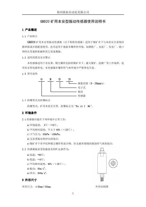
本传感器适用于有瓦斯、煤尘爆炸危险的煤矿井下、露天煤矿、选煤厂等工作场所,选 用本安型电源供电;本传感器在爆炸性气体环境中严禁带电开盖。
1.3 型号说明
G
B
D
20
测量范围(0~20mm/s)
电子式
振动 传感器
1.4 防爆型式及防爆标志
防爆型式:矿用本质安全型,防爆标志为“Ex ib I Mb”。
震动传感器产品使用说明书

震动传感器产品使用说明书一、YT-JB3A震动传感器应用:特别设计作金属和水泥墙防破坏用,适用于保险箱、金属门、密室、钱箱和银行水泥墙、自动柜员机、ATM取款机、保险箱等防击防敲物体等保护防盗保险柜是针对ATM/自助银行系统而设计研发的一种新型高灵敏度全向振动传感器,具有全向检测、灵敏度可调、高抗干扰能力、产品一致性和互换性好、体积小、可靠性高、价格低等特点。
二YT-JB3振动传感器主要性能:灵敏度:高低可调一致性及互换性:好可靠性及抗干扰:无误触发、抗干扰强自动复位:自动复位性强信号的后期处理:简单输出信号:开关信号,外观小巧,安装调试方便。
无需外接振动分析板:产品内部设计振动分析放大电路三、YT-JB3主要性能参数:1、工作电压:12VDC(红线V+ 屏蔽线V-);2、灵敏度:大于等于0.2g;3、频率范围:0.5HZ~20HZ;4、工作温度范围:-10℃~50℃;5、体积: 6.0㎝×4.5㎝×2.1㎝6、检测方向:全向。
7、信号输出:开关信号(黄/白线);8、输出脉冲宽度:与振动信号幅度成正比;控制防范:每只振动探测器可控制 10m 2 左右的房间。
灵敏度:在探测器警戒防范区内,以 60kg(±5kg)体重的人用≥1kg钢锤或其它工具打墙1-3次报警。
报警延时: 1-8秒;报警输出:继电器常闭(警戒为常闭、报警常开)。
防拆功能:打开探测器盒盖或断电源线时报警。
误报率低:在电路中采用特殊信号处理电路,使之误报率最小警戒电流≦ 47mA,报警电流≦ 30mA。
四、使用中注意的问题:YT-JB3振动传感器与其他的振动传感器一样,安装时使用粘结胶固定,以减小振动源至传感器之间的信号衰减。
电磁振动传感器操作说明书

电磁振动传感器操作说明书操作说明书一、产品概述电磁振动传感器是一种用于测量振动和震动的装置。
它采用电磁感应原理,能够准确地检测物体的振动频率和振幅,广泛应用于机械设备、交通工具和建筑结构等领域。
二、产品参数1. 测量范围:0-1000 Hz2. 灵敏度:0.5 mV/g3. 频率响应范围:10 Hz - 10 kHz4. 工作温度范围:-20℃至70℃5. 输出方式:模拟信号6. 电源要求:12-24V 直流电源三、产品结构电磁振动传感器主要由以下部分组成:1. 振动感应单元:负责感应振动信号;2. 信号处理单元:将感应到的振动信号转换为模拟信号;3. 输出接口:连接到外部设备。
四、产品安装及使用步骤1. 确保安装场所干燥、无振动干扰,并远离强电磁场。
2. 将电磁振动传感器的振动感应单元平稳地粘贴在需要测量振动的物体表面,确保良好的贴合度。
3. 将传感器的输出接口连接到外部设备的模拟输入端。
4. 将传感器的电源线连接到12-24V 直流电源,确保极性连接正确。
5. 打开外部设备的电源,并进行相应的设置。
6. 根据外部设备的要求,调整传感器的灵敏度和工作范围。
五、注意事项1. 在安装和使用过程中,严禁使用力量撞击或过度挤压传感器。
2. 请勿拆解传感器,否则会导致设备损坏或人身伤害。
3. 传感器的使用环境温度应在-20℃至70℃之间,超出范围会影响性能。
4. 如需更换传感器,请联系专业技术人员进行操作。
六、故障排除1. 如果传感器输出信号异常或无信号,请检查是否正常连接电源和信号线,并确保连接正确。
2. 如仍无法解决问题,请联系售后服务中心获取进一步帮助。
七、维护保养1. 定期检查传感器的安装状态,确保贴合度和连接可靠性。
2. 保持传感器表面清洁干燥,不得使用腐蚀性溶液进行清洗。
3. 如传感器长期不使用,请将其放置于干燥通风的地方,并避免受到机械振动。
八、报废处理1. 如需报废传感器,请联系当地相关部门进行处理,切勿随意丢弃。
Protero-915无线振动传感器使用说明书

Protero-915Wireless vibration sensorsOperating instructions (translation) Product contentsCordless motion sensor for awnings, bat-tery-operated with 2 x Mignon LR6 1.5V, fixing set and instruction manual. Safety instructionsPlease read this operating manual carefully as the procedure in this manual is a prereq-uisite for correct use of the product.Only operate the transmitter within sight of the awning drive!The figures in this operating manual are for illustration purposes only. The illustrations may differ from your product with respect to minor details and are provided for general information only.elero GmbH continuously strives to improve all products. As a result, the specifications, features and technology of this product may be changed at any time. The information in this operating manual is based on current information at the time of publication. No claims can be derived from the tech-nical data, images and information in this operating manual.&$87,21Intended use / Foreseeable misuse Only to be used for switching elero radio drives. Do not make any changes to the unit. Do not allow the device to fall, do not drill into the device and do not immerse in liquids. The manufacturer will not assume liability for damage caused by the above.FunctionThe Protero-915 is a battery-operated radio transmitter with sensors.It protects the awning by causing it to auto-matically retract when it is rattled by heavy winds or when water collects on the fabric (inclination change). A sensitivity threshold is used to detect the triggering event. The Protero 915 has been designed exclusively for use in conjunction with articulated arm awnings with a box or cartridge.ProgrammingBidirectional radio systemA bidirectional radio system transmits radio signals to a radio receiver and enables feed-back from the radio receiver to the transmit-ter. The radio signal can be sent directly to the target receiver. The target receiver car-ries out the command and sends a confirma -tion back to the transmitter (only when button is pressed). In order for bidirectional radio mode to work, all of the components involved must be able to transmit and receive radio signals. Whether bidirectional operation is possible depends on the bidirectional com-munication capability of the receiver.Compatibility with the following elero radio drives or receivers:SunTop 868 from V25, VariEco 868 from V20, Combio 868 RM from V79, Revio 868 from V12.Unidirectional radio systemA unidirectional radio system transmits radio signals to radio receivers. However, unlike in a bidirectional radio system, the radio receiver cannot send any messages to the transmitter.Parallel operation of both radio modes is not possible. After pressing the button P , the Protero-915 decides whether uni or bidirec-tional radio system will be used.Change to the other radio operating mode by deleting all transmitters (Protero-915 and hand/wall transmitters) from the receiver (press OPEN +DOWN/CLOSE +STOP +P for 6 seconds), then program again. Assembly and commissioningCheck compatibility of the accessories used before assembly.• Screwed in (with screws from the fixing set) or glued to one end of the outside or inside of the drop profile without hindering the closing of the awning.• Drill 2 holes in the drop profile according to the selected fixing element at the specified distance: Fix the base plate with the en-graved arrow “oben/up” pointing upwards (the longitudinal axis of the Protero-915 is parallel to the drop profile).Important: The batteries are not activated at delivery.• To activate, remove the insulating strips on the battery contacts.Make sure the radio link is unobstructed. Do not operate any devices on the same radio frequency nearby (e.g., wireless head-phones).• Programming the Protero-915 to the re-ceiver: see “Programming the transmitter/channel”.• Test regularly to ensure that the sensor is working properly.The Protero-915 can only protect the awning from sudden wind gusts to a limited degree due to the awning's travel time.• In the event of an impending storm, en-sure that the awning remains in a retract-ed position.After commissioning, check that the thresh-olds set allow the awning to retract. The fac t ory default setting ensures safe operation in most applications.Programming the transmitter / channel Requirement: The elero awning drive must be set and 1 elero radio transmitter must already be programmed. The Protero-915 can theoreti-cally be programmes on multiple elero awning drives. However, it is recommended for the sensor to only be programmed to the receiver on 1 awning. Important:Do not press the programming button P be-fore the receiver is in programming mode. If the receiver is not in programming mode, the transmitter channel will change to unidirection-al operation. To return to the initial state, press the STOP button and the programming button P simultaneously for 6 seconds until the LED indicator illuminates.1. Press the OPEN button, DOWN/CLOSE button and the programming button P simultaneously for 3 seconds on the trans-mitter that has already been programmed to the receiver. The LED illuminates briefly. The receiver is in programming mode.2. Press the programming button P on the Protero-915 for at least 1 second until the LED illuminates. The receiver is now in programming mode and indicates this by extending and retracting.3. Press the OPEN button (max. 1 second) after the retraction starts. The blind will stop.4. Press the DOWN/CLOSE button (max. 1 second) after the extension starts. The blind will stop. The Protero-915 is programmed. Housing base plateFollow these instructions for safe and proper use. Keep the instructions for future reference.Setting the wind sensitivity and inclina-tion sensitivityThe Protero-915 is delivered with a basic factory setting. Following assembly and commissioning, it is necessary to adjust the sensitivity of the awning to inclination and wind to suit the local conditions. There must be no wind when doing this. Wind sensitivity:1. Drive the awning to the outer end position. When this has been reached, the Prote-ro-915 will reference within 210 seconds. It is essential to wait until this time has elapsed!2. Now manually move the drop profile with the mounted Protero-915 in order to mim-ic vibrations similar to those that should cause the awning to retract.3. Depending upon the result (too sensitive or too insensitive), change the basic fac-tory setting of the “acceleration” threshold switch.Inclination sensitivity:1. Now drive the awning back to the outer end position. Wait for at least 210 seconds for the Protero-915 to reference again.2. Check the preset inclination sensitivity of 1° by very slowly pressing the drop profile in the outer end position downwards as far as the point of inclination you find accept -able and holding it there.The awning will retract after at least 210 seconds (position alarm).3. Depending upon the result (too sensitive or too insensitive), change the basic facto-ry setting of the “angle” threshold switch.Important:• Every setting that is changed must be checked.• Test regularly to ensure that the sensors are working properly. The awning is like-wise protected against the wind during extension and retraction.DisposalBatteries and old units may not be disposed of with household waste.1. Dispose of packaging in the recycling bin for cardboard and paper.2. Dispose of old batteries in the recycling bin for used batteries or have a retailer recycle them.3. Dispose of old units at an electronic waste recycling facility or have a retailer recycle them.ServiceIf malfunctions have occurred or the device has been damaged despite proper handling, contact your dealer or manufacturer. elero GmbH Antriebstechnik Maybachstr. 30 73278 Schlierbach Deutschland / Germany Tel: +49 (0) 7021 9539-0 Fax: +49 (0) 7021 9539-212 www.elero.de *************Notes on troubleshootingRepairPlease specify the item number, item de-scription, type of fault, situational circum-stances, presumed cause, unusual events prior to the problem. CleaningClean the device with a damp cloth only. Do not use cleaning agents because they can damage the plastic. WarrantyWithin the legal warranty period, we will remedy any defects caused by material or manufacturing defects by repairing or replac-ing the unit. Unauthorised modifications will void the warranty. ProgrammingTimeout after alarmIf the awning is retracted following an “posi-tion or acceleration alarm”, extension is only possible again after a timeout of approx. 15 minutes. During the timeout, any extension is stopped automatically after approximately 3 seconds and an automatic forced retraction takes place (locking movement).The timeout can be ended earlier as follows: • During the locking movement, press the STOP button on the programmed trans-mitter and then press the OPEN button. After reaching the upper end position the drive switches off, after which the time-out is ended.• On a programmed wall transmitter, move the Auto/Manual sliding switch to the other position and then back again.• On a programmes hand-held transmitter, use the selection button to switch from automatic mode to manual mode. Replacing the batteryIf the extension of the awning is interrupt-ed twice (loss movement), this is a sign of nearly empty batteries, that are in need of replacement.If the awning can no longer be extended (3 seconds extension, 1 second stop, 1 sec-ond extension, then retraction to upper end position), the batteries must be replaced. 1. If the awning is retracted, press the extension button on the hand/wall trans-mitter.2. The awning extends for approx. 3 seconds and stops briefly due to the absence of wind monitoring.3. The awning subsequently retracts. Im-mediately press the STOP button (while retracting). The awning now stops in this position.4. Disconnect the drive from the power supply.5. Unscrew central sheet metal screw with a suitable tool. Remove housing and silicone seal.6. Change the batteries. Use only Mignon LR6 (not rechargeable) batteries. Pay attention to correct polarity.7. Replace housing and silicone seal on the base plate.8. Restore power supply for drive. 9. Check entire functionality.After a battery change, the Protero-915 remains programmed on the drive. 10. D ispose of used batteries in accordance with environmental regulations.Status LED on printed circuit board When the status LED is illuminated, this indi c ates a radio signal. The same indicator light also indicates the operating mode of the receiver as follows: Inclination sensitivity when awningis stopped Wind sensitivity when awning is stopped OPEN buttonSTOP buttonDOWN/CLOSE buttonProgramming button PTransmit LEDProtero-915FCC / ICFCC ID: YBU2896IC: 8929A- 2896USA (FCC)Statement acc. to. FCC 15.19This device (elero Protero-915) complies with Part 15 of the FCC Rules . Operation is subject to the following two conditions:(1) this device may not cause harmful interference, and(2) this device must accept any interference received, including interference that may cause undesired operation.Canada, Inn ov at io n, S cie n ce and Eco n omic Developme nt (IS ED)R SS Ge n Issu e5, S ec t.8.4This device(elero Protero-915) contains licence-exempt transmitter(s)/receiver(s) that comply with Innovation, Science and Economic Development Canada’s licence-exempt RSS(s). Operation is subject to the following two con-ditions:(1) This device may not cause interference(2) This device must accept any interference, including interfe-rence that may cause undesired operation of the device.Cet appareil(elero Protero-915) contient des émetteurs / récepteurs exemptés de licence conformes aux RSS (RSS) d'Innovation, Sciences et Développement économique Canada. Le fonctionnement est soumis aux deux conditions suivantes:(1) Cet appareil ne doit pas causer d'interférences(2) Cet appareil doit accter toutes lesinterférences, y compris celles susceptibles de provoquer un fonctionnement indésirable de l'appareil.Caution:Changes or modifications not expressly approved by the party responsible for compliance could void the user’sau thority to operate the equipment.Information:This equipment has been tested and found to comply with the limits for a Class B digital device, pursuant to part15 of the FCC Rules. These limits are designed to provide reasonable protection against harmful interference in a residential installation. This equipment generates, uses and can radiate radio frequency energy and, if not installed and used in accordance with the instructions, may cause harmful interference to radio communications. However, there is no guarantee that interference will not occur in a particular installation. If this equipment does cause harmful interference to radio or television reception, which can be determined by turning the equipment off and on, the user is encouraged to try to correct the interference by one or more of the following measures:• Reorient or relocate the receiving antenna.• Increase the separation between the equipment and receiver.• Connect the equipment into an outlet on a circuit different from that to which the receiver is connected.• Consult the dealer or an experienced radio/ TV technician for help。
metrix振动传感器说明书

metrix振动传感器说明书一、产品介绍地震传感器提供以mV/g或mV/in/sec为单位的动态交流信号输出。
具有这种类型输出的设备通常用于连接到独立的振动监测系统,而不是像PLC或DCS这样的通用自动化和控制仪器。
Metrix提供具有多种工作温度、频率响应、比例因子、外壳材料、连接器类型、安装选项和危险区域认证的地震传感器。
符合API 670要求的通用加速度计。
设计用于各种机器类型,具有0.5至10 kHz(+/-3dB)的宽频率响应、50g范围和13 kHz的安装共振。
内置放大器提供符合行业标准的100mV/g低阻抗恒流输出,与振动监测系统、电子开关和4-20mA信号调节器兼容。
二、产品概述由一个温度稳定的压电核心和一个放大器组成,它们一起封装在一个与传感电路电隔离的316不锈钢外壳中。
Metrix SA6350高温加速度计适用于高达325C的温度。
它专为燃气轮机和其他需要加速度*信号的表面温度高的机械而设计。
传感器的设计使用铠装一体式电缆将电荷放大器/线路驱动器与压电传感元件分开。
这使得传感元件可以直接安装在机器上,但电荷放大器可以安装在3m或5m以外的低温环境中。
电荷放大器额定高达120C;它的安装位置通常会使其暴露在适度升高的温度下,但这些温度通常远低于传感元件位置(例如燃气轮机外壳)处遇到的表面温度。
三、产品特点提供5 Hz至10 kHz的频率响应,具有25 kHz的安装谐振,并提供与振动监测系统、电子开关和4-20mA信号调节器兼容的行业标准100 mV/g低阻抗输出。
传感元件可提供3孔或4孔平底安装模式,旨在与其他几种工业标准高温传感器相匹配。
Metrix 5485C高温速度传感器适用于高达375°C的温度。
它专为需要速度信号的具有高表面温度的燃气轮机和其他机械而设计。
Metrix 5485C是大多数GE重型工业燃气轮机的标准设备,包括Frame 3、Frame 5、Frame 6、Frame 7和Frame 9。
振动检测仪使用说明书

振动检测仪使用说明书
一、前言
振动检测仪是一种用于监测和分析机械设备振动情况的仪器。
本使用说明书旨在帮助用户正确了解和使用振动检测仪,以确保设
备的稳定运行和延长设备的使用寿命。
二、产品描述
振动检测仪是一种便携式仪器,具有高精度和高灵敏度的特点。
它可以测量机械设备的振动幅值、频率和相位等参数,并能根据测
量结果提供相应的分析报告。
三、使用步骤
1. 准备工作
a. 确保待测设备处于正常停机状态,并且已经断开与电源的连接。
b. 打开振动检测仪电源开关,并确保电量充足。
2. 连接传感器
a. 按照振动检测仪上的标识,将传感器的插口与振动检测仪的传感器接口相匹配。
b. 确保传感器的接头与设备的振动部位连接牢固。
3. 启动测量
a. 按下振动检测仪的启动按钮,并开始采集振动数据。
b. 可根据需要选择不同的测量模式和测量参数,如振动幅值、频率等。
4. 结果分析
a. 测量完成后,振动检测仪会自动分析数据,并生成相应的报告。
b. 用户可通过阅读报告,了解设备的运行状态和振动异常情况,并根据需要采取相应的维修措施。
四、注意事项
1. 在使用振动检测仪之前,请仔细阅读本使用说明书,并按照
指导操作,以确保测量结果的准确性和可靠性。