氧传感器使用说明书(详细版).(DOC)
氧传感器的功能及工作原理全解
氧传感器的功能及工作原理氧传感器的功能测定发动机排气中氧气含量,确定汽油与空气是否完全燃烧。
电子控制器根据这一信息实现以过量空气系数λ=1为目的的闭环控制,以确保三元催化转化器对排气中、和三种污染物都有最大的转化效率。
工作原理氧传感器的工作原理与干电池相似,传感器中的氧化锆元素起类似电解液的作用,其根本工作原理是:在一定条件下〔高温和铂催化〕,利用氧化锆骨外两侧的氧浓度差,产生电位差,且浓度差越大,电位差越大。
大气中氧的含量为21%,浓混合气燃烧后的废气实际上不含氧,稀混合气燃烧后生成的废气或因缺火产生的废气中含有较多的氧,但仍比大气中的氧少得多。
特点抗铅;较少依赖于排气温度;起动后迅速进入闭环控制。
氧传感器的常见故障氧传感器中毒氧传感器中毒是经常出现的且较难防治的一种故障,尤其是经常使用含铅汽油的汽车,即使是新的氧传感器,也只能工作几千公里。
假如只是细微的铅中毒,接着使用一箱不含铅的汽油,就能消除氧传感器外表的铅,使其恢复正常工作。
但往往由于过高的排气温度,而使铅侵入其内部,阻碍了氧离子的扩散,使氧传感器失效,这时就只能更换了。
积碳由于发动机燃烧不好,在氧传感器外表形成积碳,或氧传感器内部进入了油污或尘埃等沉积物,会阻碍或阻塞外部空气进入氧传感器内部,使氧传感器输出的信号失准,不能及时地修正空燃比。
产生积碳,主要表现为油耗上升,排放浓度明显增加。
此时,假设将沉积物去除,就会恢复正常工作。
氧传感器陶瓷碎裂氧传感器的陶瓷硬而脆,用硬物敲击或用强烈气流吹洗,都可能使其碎裂而失效。
因此,处理时要特别小心,发现问题及时更换。
加热器电阻丝烧断对于加热型氧传感器,假如加热器电阻丝烧蚀,就很难使传感器到达正常的工作温度而失去作用。
氧传感器内部线路断脱氧传感器的常见故障及检查方法在使用三元催化转换器以减少排气污染的发动机上,氧传感器是必不可少的元件。
由于混合气的空燃比一旦偏离理论空燃比,三元催化剂对、和的净化才能将急剧下降,故在排气管中安装氧传感器,用以检测排气中氧的浓度,并向发出反响信号,再由控制喷油器喷油量的增减,从而将混合气的空燃比控制在理论值附近。
iO2气体传感器技术规范说明书
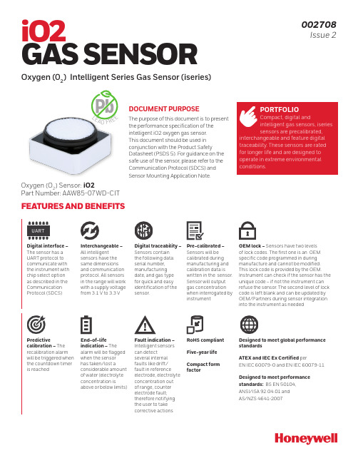
DOCUMENT PURPOSEThe purpose of this document is to present the performance specification of the intelligent iO2 oxygen gas sensor. This document should be used in conjunction with the Product SafetyDatasheet (PSDS 5). For guidance on the safe use of the sensor, please refer to the Communication Protocol (SDCS) and Sensor Mounting Application Note.iO2GAS SENSOROxygen (02) Intelligent Series Gas Sensor (iseries)002708Issue 2Oxygen (O 2) Sensor: iO2Part Number: AAW85-07WD-CITL EA D F R E EPORTFOLIOCompact, digital andintelligent gas sensors, iseries sensors are precalibrated,interchangeable and feature digital traceability. These sensors are rated for longer life and are designed to operate in extreme environmental conditions.FEATURES AND BENEFITSUARTDigital interface – The sensor has a UART protocol to communicate with the instrument with chip select option as described in the Communication Protocol (SDCS)Interchangeable – All intelligent sensors have the same dimensions and communication protocol. All sensors in the range will work with a supply voltage from 3.1 V to 3.3 VDigital traceability – Sensors contain the following data: serial number, manufacturing date, and gas type for quick and easy identification of the sensor.Pre-calibrated – Sensors will be calibrated during manufacturing and calibration data is written in the sensor. Sensor will output gas concentration when interrogated by instrumentOEM lock – Sensors have two levels of lock codes. The first one is an OEM specific code programmed in during manufacture and cannot be modified. This lock code is provided by the OEM. Instrument can check if the sensor has the unique code – if not the instrument can refuse the sensor. The second level of lock code is left blank and can be updated by OEM/Partners during sensor integrationinto the instrument as neededPredictivecalibration – The recalibration alarm will be triggered when the countdown timer is reachedEnd-of-lifeindication – The alarm will be flagged when the sensor has taken/lost aconsiderable amount of water (electrolyte concentration isabove or below limits)Fault indication – Intelligent sensors can detectseveral internal faults like drift/fault in reference electrode, electrolyte concentration out of range, counter electrode fault; therefore notifying the user to take corrective actionsRoHS compliant Five-year life Compact form factorDesigned to meet global performance standardsATEX and IEC Ex Certified perEN IEC 60079-0 and EN IEC 60079-11Designed to meet performance standards: BS EN 50104, ANSI/ISA 92.04.01 and AS/NZS 4641-2007‡ For mounting and sealingaround sensor, refer to iseriesSensor Mounting ApplicationNote.Product DimensionsAll dimensions in mmDo not connect tounlabeled pins.between 3.1 V and 3.3 V.prior to installation.recommended circuitry. Performance characteristics outline the performance ofsensors supplied within the first three months. Output signal can drift below thelower limit over time.† For best accuracy, it is recommended that a ‘baseline’ calibration is performedin clean ambient air when a new sensor has been installed into the instrument.iO2 Series Gas Sensor Datasheet | /ast | 2PoisoningGas sensors are designed for operation in a wide range of environments and harshconditions. However, it is important that exposure to high concentrations of solventvapours is avoided, both during storage, fitting into instruments, and operation. Whenusing sensors with printed circuit boards (PCBs), degreasing agents should be usedbefore the sensor is fitted.Do not glue directly on or near the sensor as the solvent may cause crazing of theplastic.iO2 Series Gas Sensor Datasheet | /ast | 4WARRANTY/REMEDYHoneywell warrants goods of itsmanufacture as being free of defective materials and faulty workmanship during the applicable warranty period. Honeywell’s standard product warranty applies unless agreed to otherwise by Honeywell in writing; please refer to your order acknowledgment or consult your local sales office for specific warranty details. If warranted goods are returned to Honeywell during the period ofcoverage, Honeywell will repair or replace, at its option, without charge those items that Honeywell, in its sole discretion,finds defective. The foregoing is buyer’s sole remedy and is in lieu of all other warranties, expressed or implied, including those of merchantability and fitness for a particular purpose. In no event shall Honeywell be liable for consequential, special, or indirect damages.While Honeywell may provide application assistance personally, through ourliterature and the Honeywell web site, it is buyer’s sole responsibility to determine the suitability of the product in the application.Specifications may change without notice. The information we supply isbelieved to be accurate and reliable as of this writing. However, Honeywell assumes no responsibility for its use.002708-2-EN | 2 | 08/21© 2021 Honeywell International Inc. All rights reserved.m WARNINGMISUSE OFDOCUMENTATION•The information presented in this product sheet is for reference only. Do not use this document as a product installation guide.•Complete installation, operation, and maintenance information is provided in the instructions supplied with each product.Failure to comply with theseinstructions could result in death or serious injury.SAFETY NOTEThis sensor is designed to be used in safety-critical applications. To ensure that the sensor and/or instrument in which it is used, are operating properly, it is a requirement that the function of the device is confirmed by exposure to target gas (bump check) before each use of the sensor and/or instrument. Failure to carry out such tests may jeopardize the safety of people and property.Under no circumstances should intelligent sensor pads be soldered to, as this can cause leakage of electrolyte. Connection should be made via a mounting socket and spring connector.WARNING: SOLDERING TO PADS WILL RENDER YOUR WARRANTY VOID.HoneywellAdvanced Sensing Technologies 830 East Arapaho Road Richardson, TX /astFOR MORE INFORMATIONHoneywell Advanced Sensing Technolo-gies services its customers through a worldwide network of sales offices and distributors. For application assistance, current specifications, pricing, or the nearest Authorized Distributor, visit /ast or call:USA/Canada +302 613 4491Latin America +1 305 805 8188Europe +44 1344 238258Japan +81 (0) 3-6730-7152Singapore +65 6355 2828Greater China+86 4006396841。
氧化锆说明书1

其中E是氧电势, R是气体常数,T是绝对温度值, PO2 INSIDE是氧在氧化锆管里部的气压值
,PO2 OUTSIDE是氧在氧化锆管外部的气压值.根据公式当氧化锆管里部和外部的氧浓度不同时,就会产生相应的氧电势.
从计算公式可知道当氧化锆管里部和外部的氧浓度相同时,氧电势应该是0毫伏.
220V的灯泡来替代加热器进行测试,当加热电压输出时(发光二极管闪亮时,电灯泡也应该同时闪亮.当一切测试正常后再把加热器接入.这样测试比较保险,不易损坏加热器
仪器有7键,每键有两种功能。一种是运行时的功能,一种是设定时的功能。当仪器在运行状态RUN时,按Display键,仪器的下行显示仪器的有关信息,比如探头的温度TEMP,探头氧的电信号EMF,探头的阻抗IMP等各种有用的参数。如报警指示灯闪亮,按ALARM键,可在下行显示报警指示的信息。CAL1键在运行状态时,可执行校正功能。CAL2键是校正功能第二键,该仪器可用2种标准气体进行自动和手动的校正(一般用于精度高的测量,可按低值和高值氧的标准气自动进行校验,详细情况请查阅使用手册)。PURGE键是清尘键。另外Autocal键在设定状态时按此键,可对仪器自动校正,运行时可手动检查探头的阻抗值。当按Setup键时,该指示灯亮进入设定状态,此时按△Function键和▽Function功能键,可显示要设定的状态,在显示屏的上行会出现1,2,3,4……76等,按△Option和▽Option选择键时,可设定有关的值。每次改变有关的设定后,必须按ENTER确认键,以便仪器记住要改变的值,这时在显示屏的右下角会出现*星号,如无此*星号出现,改变值无效。
5.528.615Βιβλιοθήκη 030.654.532.90
4.035.42
美国GEO2X1氧分析仪中文操作手册

O2X1中文使用指导埃登威自动化系统设备(上海)有限公司目录安装传感器—————————————————————— 3 O2X1用户编程—————————————————————— 4进入主菜单———————————————————4退出菜单———————————————————4 校准并调整O2X1 —————————————————————— 4选择量程范围———————————————————5调整输出———————————————————5量程气校准———————————————————6空气校准———————————————————7 更换传感器——————————————————————8 规格——————————————————————10 O2X1接线图——————————————————————11 附:O2X1菜单框图——————————————————————12安装传感器安装氧传感器,按以下步骤进行:1、用非危险性的低氧含量气体(例如:高纯氮气)吹扫取样系统。
在正常工作时,要求通入传感器测试头的气体为500cc/min(1.0SCFH),压力为大气压。
持续通入该气体,直到完成传感器的安装。
2、在安装前,请先熟悉O2X1编程和校准的步骤(见页2-6)。
然后,调整4-20mA模拟输出,并将测氧的量程范围设置到0-25%O2。
3、打开密封盒(见页1的图3),取出氧传感器。
为了保持氧传感器的能量,立即除去红色贴片,进行下一步。
4、调整传感器,让它的金层电极对准变送器的底座上具有弹性的接触管脚(见页1中图4)。
用手将传感器紧紧压在O2X1变送器上。
5、最好此时对新传感器进行空气校准(见页5)。
在0-25%的氧量程范围时,正确的传感器校准会使变送器4-20mA的模拟输出端输出17.4mA的电流。
6、用滚花螺母将校准过的传感器封装在变送器的测试头内,调整好变送器的位置(最好按键朝外),用手拧紧滚花螺母。
Endress+Hauser CM14变送器与溶解氧传感器操作手册说明书
Products Solutions Services操作手册CM14变送器,与溶解氧传感器搭配使用BA01033C/28/ZH/03.19714872492019-12-31固件版本号:不低于02.01.CM14目录Endress+Hauser 3目录1安全指南 (4)1.1工作场所安全 (4)1.2人员要求 (4)1.3操作安全 (4)1.4指定用途 (4)1.5技术更新 (5)1.6返厂 (5)1.7安全图标和符号说明 (5)2标识 (7)2.1设备名称 (7)2.2供货清单 (7)2.3证书和认证 (8)3安装 (9)3.1到货验收、运输、储存 (9)3.2安装条件 (9)3.3外形尺寸 (9)3.4安装步骤 (9)3.5安装后检查 (10)4接线 (11)4.1连接变送器 (12)4.2连接后检查 (13)5操作 (14)5.1显示屏和设备状态指示灯/ LED (14)5.2通过设备进行现场操作 (14)5.3图标 (15)5.4操作功能 (16)5.5保持功能 (16)6调试 (17)6.1安装后检查和设备通电 (17)6.2显示设置(Display 菜单) (17)6.3设置访问保护的注意事项 (17)6.4设备设置(Setup 菜单) (18)6.5扩展设置(Extended Setup 菜单) (19)6.6设备诊断(Diagnostics 菜单) (21)7标定 (22)7.1术语 (23)7.2设备的标定功能 (24)8维护 (25)9附件............................269.1传感器............................2610故障排除.......................2710.1故障排除指南......................2710.2诊断信息..........................2710.3固件更新历史......................3010.4备件..............................3110.5返厂..............................3110.6废弃..............................3211技术参数.......................3211.1输入..............................3211.2输出..............................3211.3有源电流输出......................3311.4继电器输出........................3311.5接线..............................3411.6性能参数..........................3511.7安装条件..........................3511.8环境条件..........................3611.9机械结构..........................3711.10显示与操作单元....................3811.11证书和认证........................38索引. (39)安全指南CM144Endress+Hauser1安全指南必须阅读《操作手册》并遵守安全指南要求,才能确保变送器的安全操作。
氧传感器技术手册

氧传感器使用说明书 (第一版)适用零件号:25327985 253599081.概述氧传感器是现代发动机管理系统中必不可少的重要零部件。
它是一种利用电化学工作原理发展出来的电器元件。
氧传感器在现代发动机管理系统的配置机构中被用于探测汽车发动机所排出的燃烧废气中氧的含量,借以判定发动机实时燃油供给空气燃料混合比的实际状态,并通过自身产生的电器反应信号反馈给发动机电子控制模块(ECM),以作为系统燃油管理系统的闭环燃油修正补偿控制的重要依据,使燃油管理子系统能够更加精确地控制调整发动机各种工作状态下的空气燃料混合比;并在绝大多数工况下使系统保持在理想空燃比工作状态,以便获得更加优良的汽车排放控制特性和燃油经济性。
氧传感器的输出信号为0 ~ 1V的交变电压信号。
传感器可根据发动机所排燃烧气中氧的含量高低自动感应和探测并向发动机电子控制模块输出这一高低变化的电压信号。
现代发动机管理系统采用的氧传感器有两种主要类型:非加热型氧传感器和加热型氧传感器。
装配在发动机排气歧管上的氧传感器,由于可以利用发动机所排出燃烧废气的余热进行快速加热,故可使用价格低廉的非加热型氧传感器;当氧传感器的安装位置受到整车布置限制,氧传感器距离发动机排气歧管出口较远时,由于不能利用发动机燃烧废气对于传感器迅速加热,此时必然需要采用加热式氧传感器。
加热式氧传感器的内部设计有热敏电加热元件,可利用系统供电电压强制使氧传感器加速预热,促使其快速起燃,及早实现系统的闭环燃油管理控制。
2. 工作原理德尔福公司生产的氧传感器是采用氧化锆元件作为传感器的基础元件。
氧化锆元件是一种通体充满无数微孔的陶瓷基础元件外面镀有氧化锆涂层,该涂层外测暴露于发动机燃烧废气之中;涂层的内侧透过含微孔的陶瓷元件与大气相通。
集中在氧化锆内外两侧电极之间氧含量的差别形成的微分电压信号。
当氧化锆元件被电流加热或被流经传感器的发动机燃烧废气加热所激活,空气经过通体充满无数微孔的陶瓷基础元件进入氧化锆元件的内电极,而燃烧废气流经氧化锆的外电极。
派特克溶解氧传感器和发射器应用说明书
AVAILABLETRANSMITTERS7300w 2 Monitor Atlantic Monitor 840 TransmitterMOUNTING OPTIONS FlexT ech Probe HolderFlowcell Fixed Dip T ubeMEASUREMENT PRINCIPLESelf Polarising Self T emperature Compensating, Galvanic, membranecovered cellFEATURESLong life probe – 5 years+Very low maintenanceEasy to calibrateBENEFITSImproved Aeration Control Prevention of Discharge FailureEnergy SavingsPartech Galvanic Sensors and T ransmittersAPPLICATION DATASHEETBeing able to act on accurate measurements of Dissolved Oxygen in activated sludge plants will enable you to maintain levels of bacterial activity, avoid breaches in discharge consents and operate as cost effectively as possible. T oo little dissolved oxygen can lead to bacterial inactivity and ineffective treatment, whilst too much, wastes energy and can cause unnecessary wear and tear to the aeration system.Partech's sensors make accurate dissolved oxygen measurement easy. They are highly reliable and accurate as well as straightforward to use and easy to install. They also benefit from the self cleaning action of the Pioneer probe holder and the fouling tolerance of the probes themselves – all of which mean longer service intervals and a consistently more efficient plant.The Oxyguard probe utilises a unique combination of electrolyte, membrane and anode materials, together these factors give a real world working life in excess of five years. The Iron/Silver electrode combination ensures that no gas can build up in the cell and the electrolyte is not consumed, there is no warm up time and no zero adjustment required. The only maintenance is occasional removal of fouling and calibration.Routine calibration is required for any instrumentation, without it there is no validation of the measurement. The Oxyguard probe is easily repaired on site without specialist training, the membrane is quick and easy to replace.T ransmitter OptionsPRODUCT DATASHEET7300w2 MonitorPartech's latest generation, multisensor,multiparameter monitor provides an exceptionally flexible solutionto monitoring water, wastewater and surface water parameters such as Dissolved Oxygen. The monitorallows the user to combine multiple sensors for use on large sites and to add parameters such as pH,andSuspended Solids.840 TransmitterThe 840 T ransmitter is a loop powered device designed for simplicity of use, the system can be selected withranges from 0-5 to 0-40 mg/l, or 0-5%Sat to 0-400%Sat. The only user requirement is to carry out periodiccalibration.Atlantic MonitorIn common with all the systems mentioned in this datasheet the probe will only need renovation if it isdamaged. In most applications the probe life is in excess of 5 years. Even when it does require attentionthere is no need to dispose of the probe,simply replace the membrane and electrolyte.The newly introduced Atlantic has been designed for applications where the Dissolved Oxygen system isused to control a process or where the system is required to produce alarms at different levels. It has 4relays and a 4 - 20 mA output, a 4 – 20 mA compensation input can be added.The Atlantic incorporates 8alarm set points.Calibration of the probe is done automatically and checked and validated by the system,the operator hasonly to remove the probe from the effluent, wipe it clean and leave it in air to temperature equilibrate. Oncethe temperature is stable press the button and the system completes and validates the calibration.EasyCal Calibration DeviceDesigned to improve the simplicity and reliability of the calibration the EasyCalcalibrates the probe at the point of measurement. This removes temperature as avariable which can have a very dramatic effect on the oxygen saturation in the air.The Easy Cal fits over the end of the probe, the probe is returned to the sample andair is blown across the membrane by a pump mounted in the EasyCal this is leftrunning for 10 minutes to allow it to temperature equilibrate with the sample andthen the calibration is performed by either setting the system to 100 % or to themg/l setting as displayed on the EasyCal.EasyCal can be used on the 7300w2, 840, or the Atlantic.Product BackgroundPRODUCT DATASHEETPartech and Dissolved OxygenFor over 30 years Partech has been a manufacturer and supplier of Dissolved Oxygen measurement systems. During this time we have gained experience of a wide range of measurement techniques and have amassed a huge knowledge of the trials and tribulations of DO measurement in Wastewater treatment.Since 1997, Partech have been the UK distributor for Oxyguard International of Denmark.During this time we have generated a large installed base of Oxyguard sensors in the UK.We are proud to continue this association with the integration of the famed Oxyguard probe into our product range.Currently Available Measurement CellsThe use of sensors to measure Dissolved Oxygen was started over 50 years ago by Dr Clark initially in the medical industry and then in water analysis. The Clark cell and it's close cousin the Makereth cell are electrochemical (galvanic)cells where an electrical circuit consisting of an anode and cathode with an electrolyte sitting behind a gas permeable membrane. As the oxygen diffuses through the membrane a chemical reaction takes place that generates an electrical signal that is proportional to the amount of Oxygen present in the sample. Oxyguard have developed their probe so that this electrochemical reaction does not consume the electrolyte or anode,thus providing a measuring cell that has an operational life of 10 years or more. Recently a technology from the 1970's has been revived, optical DO measurement has been offered as an alternative for all issues relating to monitoring in wastewater environments. Basically, the meter determines oxygen by measuring light.High-energy blue light is directed onto the sensor surface,which is coated with a luminescent material. Electrons of the luminescent material are excited to a higher energy level before then falling back to their basic energy level, emitting red light as they do so. This light is detected by a photo diode. Partech are now able to offer this technology in the WaterWatch2 range.Strength of the Partech solutionThe combined skills of Partech and Oxyguard with our reputations for simple, common sense solutions to measurement challenges means we can offer reliable Dissolved Oxygen measurement. Use of the FlexT ech mounting system helps alleviate the problems of fouling, and ensures that the sensor is located correctly for representative measurement. The unique combination of electrolyte, anode and cathode material, and physical probe design gives real world life of in excess of five years with many lasting much,much longer.The membrane for the cell is only replaced if it is damaged, there is no internal drift, and the internal sensor design means that the electrolyte and anode are not consumed.The Oxyguard probe benefits from being left alone, the first line of the maintenance section of the manual is 'Leave it alone'.PRODUCT DATASHEET Publication No: 221334DS-Iss03The company reserves the right to alter the specification without Probe Specifications Measurement PrincipleOxygen: galvanic oxygen partial pressure cell, self polarising, selftemperature compensating. T emperature: Precision NTC Dimensions Diameter: 58 mm Length: 59 mmWeight Probe only 0.2 kgProbe with 7 metres of cable: 0.5 kg Connections: Atlantic and 7300w 2: 4 lead840: 3 leadCable length (Std, other available)Atlantic: 7 metres840 and 7300w 2: 10 metresDO Measurement Range 0 – 20 mg/l (ppm) 0 – 200% sat, (higher on request) T emperature Range from -5°CAccuracy Depends on calibration and conditions. T ypically better than +/-1% of value.Output Stability In air at constant temperature stable to within +/-1% over 1 year Accuracy T emperature +/- 0.3COperating Conditions 0 – 40 C, Pressure to 2 bar. (higher on request)Storage temperature-5 to +60 CFlexT ech Mounting BracketThe FlexT ech mounting system has been designed to keep the DO probe in the optimum position within the matrix and provide a simple light weight and robust system to keep the probe clean and free of rags and other debris which slide off the shaft producing a self cleaning action.Fats and greases which are normally on the top of the sample tend to build up above the probe as it is mounted approximately 300 mm below the surface. An additional benefit of keeping the probe below surface is that is provides a more representative reading of the oxygen level in the tank, the surface being effected by rain and the natural tendency of oxygen to rise in the liquid.Alternative Mounting OptionsWhere a dip probe is not appropriate, alternative mounting options are available, such as a full bore flow through cell.Anti-Fouling CapThe Oxyguard anti-fouling Cap inhibits growths on the membrane of the probe, especially in seawater applications.The cap is essentially the same as the normal cap, but is fitted with a cone made from aspecially developed alloy. The cone surrounds the membrane and is effective in inhibiting marineorganisms from attaching to and growing on the membraneTypical Installation with a FlexTech Probe Holder63 m m I D140 mm75 m m O DFlow Through T-PieceSpecification and Mounting Details。
氧传感器使用说明书(详细版)
1.概述氧传感器是现代发动机管理系统中必不可少的重要零部件。
它用于探测汽车发动机排气管中燃烧废气中氧的含量,借以判定发动机实时空燃比状态。
根据氧浓度的不同,传感器将输出高低不同的电压信号给发动机电子控制模块(ECM),作为系统闭环燃油修正补偿控制的重要依据。
由于氧传感器的应用,发动机能在绝大多数工况下工作在理想空燃比状态,从而获得良好的排放特性和燃油经济性.本公司加热式氧传感器尺寸小巧,起燃迅速,可使发动机管理系统及早实现系统的闭环燃油管理控制。
图一氧传感器外观2.工作原理氧传感器采用平板结构多层氧化锆陶瓷作为核心元件.ABCD 图3 接线端子图示7.安装与调试7.1安装位置要求●控制用氧传感器(前氧传感器)安装布置前氧传感器应安装于可以代表所有汽缸排出废气状态的位置附近.此外各个气缸排气气流混合均匀,避免只探测到发动机某单一汽缸的废气氧浓度,从而影响整个系统对发动机实时燃烧状态作出正确判断。
为了使系统在冷启动时尽快进入闭环控制,传感器应安装在离发动机排气歧管出口较近、气流温度较高的位置.图4前氧传感器安装位置●三元催化器功能监测用氧传感器(后氧传感器)安装布置:后氧传感器的理想安装位置推荐在三元催化器下游外壳的延长管上且距催化器载体后端面100~300毫米以内。
当催化器与排气消音器之间带有装配法兰时,为了防止因联结法兰漏气造成错误判断,应将传感器布置在三元催化器一侧联结法兰上游。
图5后氧传感器安装位置图7氧传感器安装凸台7.2 安装方向要求● 氧传感器的装配位置选择应注意避免路面砂石直接冲击或飞溅到氧传感器的外壳及传感器的线束上。
● 氧传感器安装方向应尽可能减少冷凝水在氧传感器头部附近聚积,避免排气中冷凝水损坏锆元件。
氧传感器头部应朝下装配,且其装配孔轴心线与水平面夹角不小于10度.图6 氧传感器安装角度7.3 安装凸台要求:● 装配凸台材料:不锈钢● 凸台最小外直径:不小于26毫米 ● 凸台推荐最大厚度:不大于13毫米(9~13毫米之间为佳)● 螺纹孔尺寸:M18×1。
氮氧传感器使用说明书
氮氧传感器使用说明书氮氧传感器使用说明书一、产品概述氮氧传感器是一种用于检测环境中的氮氧化物浓度的仪器设备。
它能够通过检测氮氧化物的浓度来评估空气的质量,并且具有高精度、高灵敏度、高稳定性的特点。
本产品主要适用于工业生产过程的环境监测、环保监测、室内空气质量检测等领域。
二、产品组成1. 传感器主体:包括传感器元件、传感器电路板和外壳。
2. 连接线:用于将传感器主体与检测设备连接。
3. 使用说明书:详细介绍了传感器的使用方法、注意事项等信息。
三、安装与连接1. 将传感器主体安装在待测区域。
建议将传感器安装在离地面1-2米的位置,保持传感器通风良好。
2. 将连接线插入传感器主体与检测设备的对应接口,并确保连接稳固。
四、使用方法1. 接通电源,按下电源开关,此时传感器开始工作。
2. 在检测设备上选择相应的氮氧传感器测量模式,并设置好相关参数,如采样时间间隔、报警阈值等。
3. 检测设备将定时采集传感器的输出信号,并转化为氮氧化物的浓度值。
4. 根据测量结果进行分析和判断,以评估空气质量。
五、注意事项1. 传感器使用过程中请勿拆卸或损坏传感器外壳,以免影响传感器的测量精度和稳定性。
2. 使用前请检查传感器及连接线是否完好,若有损坏请及时更换。
3. 请勿将传感器暴露在高温或潮湿环境中,以免影响传感器的使用寿命。
4. 如需更换传感器元件,请联系专业技术人员进行维修或更换。
5. 传感器运输或存储时,请避免震动和碰撞,以免影响传感器的正常工作。
6. 请勿将传感器用于超出其测量范围的环境中,以免影响传感器的准确度和可靠性。
六、维护与保养1. 定期清洁传感器外壳及传感器元件表面,确保其表面清洁。
2. 避免使用有腐蚀性的溶剂或洗涤剂进行清洗,以免损坏传感器。
3. 定期检查连接线的插头是否松动,如有松动请及时固定或更换。
七、故障排除若传感器无法正常工作,请检查以下问题:1. 传感器电源是否正常连接。
2. 连接线是否松动或损坏。
高温氧探头使用说明
请用户仔细阅读说明书后再使用高温氧探头一、概述高温氧探头是指使用温度在1000℃——1700℃范围内的测氧传感器。
主要是使用在玻璃炉窑,特种陶瓷炉窑,特种钢轧钢炉,真空炉测氧以及其他高温测氧场合。
其他特点是:⑴使用进口焊接式氧化锆传感器,具有良好的密性。
热震性和机械性能。
⑵由于使用温度高,外面的保护管使用刚玉管(一般氧探头使用高温合金管)⑶内外电极采用比较粗的铂金丝来代替镍洛合金丝和管。
所以生产成本比较高。
所以高温氧探头的价格要比一般氧探头高得多。
⑷一般氧探头由于合金管的热胀冷缩,为了保证传感器的良好电气接触性,传感器在弹簧的推力下,可作数毫米的移动,移动间隙可用真空脂或硅橡胶圈密封。
在一般渗碳炉中完全可以实现密封。
而在真空炉中则会发生严重渗漏。
高温氧探头是完全气密的,又可以在1200℃以上的温度中使用,可以适用于真空炉。
(5)高温氧探头有A,B两种。
A:只有一个气路,也就是参比气路(空气含氧量20.9%)B:有两个气路(1)参比气路(空气-含氧量20.9%)(2)标准气路(通入标准气对氧探头进行校对)标准气路相当于一般氧探头的自动除碳气路,由于高温氧探头使用温度很高,如果通入空气燃后温度猛然升高会造成刚玉管和传感器的损坏。
如果通入1%氧含量的标准气,和1PPM 氧含量(百万分之一)的标准气,可以对测氧仪数据进行校正。
一般在工业现场用的高温氧探头都采用A型,因为现场采用标准气校正仪表十分困难。
因为现场很难提供合格的标准气。
现场操作常常采用一根标准氧探头来校队仪表,我们认为标准氧探头是基准,其他氧探头都采用标准氧探头来校队仪表。
过程是这样的,把要校正的氧探头卸下来,把标准氧探头装上去等信号稳定后就可以对仪表进行校正,只有在特定条件下可以采用B型氧探头,如实验等。
二.工作原理焊接时的氧化锆传感器,氧化锆内外两侧分别处在两种不同的气氛中,管子内部通的是参比气(空气含氧量为20.9%)管子外部是放置在炉窑气氛中。
- 1、下载文档前请自行甄别文档内容的完整性,平台不提供额外的编辑、内容补充、找答案等附加服务。
- 2、"仅部分预览"的文档,不可在线预览部分如存在完整性等问题,可反馈申请退款(可完整预览的文档不适用该条件!)。
- 3、如文档侵犯您的权益,请联系客服反馈,我们会尽快为您处理(人工客服工作时间:9:00-18:30)。
图一氧传感器外观
A
B
C
D 图3 接线端子图示
图4前氧传感器安装位置
三元催化器功能监测用氧传感器(后氧传感器)安装布置:
后氧传感器的理想安装位置推荐在三元催化器下游外壳的延长管上且距催化器载体后端300毫米以内。
当催化器与排气消音器之间带有装配法兰时,为了防止因联结法兰漏气造成错误判断,应将传感器布置在三元催化器一侧联结法兰上游。
图5后氧传感器安装位置
图6 氧传感器安装角度
安装凸台要求:
装配凸台材料:不锈钢
凸台最小外直径:不小于26毫米
凸台推荐最大厚度:不大于13毫米
9~13毫米之间为佳)
螺纹孔尺寸:M18×1.5-7G
螺纹质量:表面应无行刺,砂眼,或
其他任何可能影响安装和拆卸的缺陷
图7氧传感器安装凸台。
图8后氧传感器橡胶密封塞结构
后氧传感器与车身穿越装配孔的推荐尺寸为25.0~25.2毫米;适于钢板厚度其他装配要求:
氧传感器安装扭矩:40~60Nm。