氧传感器使用说明书(详细版)
PE氧探头说明书
PE CS/CCS系列氧探头使用说明书使用前务必仔细越多!1.准备:1.1 要确保氧探头顶部锆头部分运输安全,因此有一个塑胶部件用来代替原有的锆件,通过旋开外管,可以拿下塑料元件已安装原来的锆件。
锆件将放入一个小的塑料容器内运输,他将被装进测量单元的终端连接盒。
如果氧探头交付,准备安装,你会发现一个随附的包装,即以上说明的这一点。
注意:陶瓷外管和锆件上的安装孔是不对称的,可以通过轻微的旋转调整,使它们安装到一起。
在除去塑胶部分安装好锆件后,外管必须逆着弹簧压力旋回。
注意:1.1是探头出口包装的首选的方法。
CCS 2000型准备交货安装时锆件已不能移动。
1.2 氧探头使用必须提供参比气,氧探头有连接参比气的接口。
参比气可以从ESS-ELECTRONIC单元提供,但事先要用硅胶管将其与接氧探头连接起来。
我们建议硅胶管型4 × 1,5或3 × 1,5 。
如果需要烧炭功能(几乎所有渗碳气氛都是必要的),供气单元可以提供一定量的必要的烧炭气体。
更多信息查询5.22,5.23。
2. 氧探头的插入和安装氧探头可以直接插入热炉内,需要的步骤描述在(1)内一定要小心太热和易燃的炉内气氛外泄。
这些气体有毒或具有潜在的危险。
2.1使用软管连接参比气到氧探头,通过调节参比气流量,使参比气值流量大约为5-10l/h。
2.2连接控制器的两个插头(圆柱形,银色的接头,一个热电偶,一个为测量电压)。
一般配置如下:探头电压:2极插头,1为正,2为负;温度:4极插头,4为正,3为负;电机:5极插头,1,2和PE。
2.3连接运行电压适用于机械装置旋转,使用红色直角连接器(电机缓慢旋转—每小时2圈-几乎看不到)。
2.4从控制器的显示中观察升温及电压上升。
2.5当炉温达到要求,氧探头准备工作,有可能测量电压读数显示值过低或者过高。
这是一些残留污物蒸发的结果(油污等),正常情况通常在2-3小时后停止。
2.6必须控制正确的参比气流量。
氧化锆说明书1

其中E是氧电势, R是气体常数,T是绝对温度值, PO2 INSIDE是氧在氧化锆管里部的气压值
,PO2 OUTSIDE是氧在氧化锆管外部的气压值.根据公式当氧化锆管里部和外部的氧浓度不同时,就会产生相应的氧电势.
从计算公式可知道当氧化锆管里部和外部的氧浓度相同时,氧电势应该是0毫伏.
220V的灯泡来替代加热器进行测试,当加热电压输出时(发光二极管闪亮时,电灯泡也应该同时闪亮.当一切测试正常后再把加热器接入.这样测试比较保险,不易损坏加热器
仪器有7键,每键有两种功能。一种是运行时的功能,一种是设定时的功能。当仪器在运行状态RUN时,按Display键,仪器的下行显示仪器的有关信息,比如探头的温度TEMP,探头氧的电信号EMF,探头的阻抗IMP等各种有用的参数。如报警指示灯闪亮,按ALARM键,可在下行显示报警指示的信息。CAL1键在运行状态时,可执行校正功能。CAL2键是校正功能第二键,该仪器可用2种标准气体进行自动和手动的校正(一般用于精度高的测量,可按低值和高值氧的标准气自动进行校验,详细情况请查阅使用手册)。PURGE键是清尘键。另外Autocal键在设定状态时按此键,可对仪器自动校正,运行时可手动检查探头的阻抗值。当按Setup键时,该指示灯亮进入设定状态,此时按△Function键和▽Function功能键,可显示要设定的状态,在显示屏的上行会出现1,2,3,4……76等,按△Option和▽Option选择键时,可设定有关的值。每次改变有关的设定后,必须按ENTER确认键,以便仪器记住要改变的值,这时在显示屏的右下角会出现*星号,如无此*星号出现,改变值无效。
5.528.615Βιβλιοθήκη 030.654.532.90
4.035.42
氧传感器的使用说明(详细版本)。.doc

氧传感器的使用说明(详细版本)。
.氧传感器(四线芯片型)说明手册1。
概述氧传感器是现代发动机管理系统中必不可少的重要部件。
它用于检测汽车发动机排气管内燃烧废气中的氧含量,从而确定发动机的实时空燃比状态。
根据不同的氧浓度,传感器会向发动机电子控制模块输出不同的电压信号,作为系统闭环燃油修正补偿控制的重要依据。
由于氧传感器的应用,发动机在大多数工况下都能工作在理想的空燃比状态,从而获得良好的排放特性和燃油经济性。
该公司的加热型氧传感器体积小、起燃快,使发动机管理系统能够尽早实现系统的闭环燃料管理控制。
图1氧传感器2的外观。
工作原理氧传感器采用扁平结构的多层氧化锆陶瓷作为核心元件。
氧化锆元素的工作原理相当于一个简单的固体原电池。
根据电化学原理,由于氧离子浓度的不同,两侧电极之间会存在电位差。
由于外电极暴露于废气,氧离子浓度将根据实际工作条件而变化,而内电极是参考空气,并且氧离子浓度是恒定的。
当发动机的空燃比稀时,排气中的氧离子浓度相对较高,并且内电极和外电极之间的氧离子浓度差小,即电势差小,并且氧传感器的输出电压信号接近0V。
相反,当空燃比浓时,排气中的氧离子浓度相对较低,并且内电极和外电极之间的氧离子浓度差大,即电势差大,并且传感器的输出电压接近1V。
氧气传感器的典型响应曲线如下图所示。
图2氧传感器的典型响应曲线(在450℃发动机测功机上测量)3。
结构特点我公司生产的现代发动机管理系统中使用的氧传感器的主要特点是:l全球统一设计,全球采购系统能保证全球产品性能的一致性;也可根据客户图纸要求制作。
符合客户要求的L型氧传感器连接器具有防水功能。
我有很短的点火时间和快速反应。
l具有通用接口结构设计。
很容易满足不同客户的需求。
l具有超强的低温适应性。
l 具有超强的抗杂质中毒性能。
l设计可防止表面化合物烧结。
l使用不锈钢丝。
我工作可靠。
L具有防错设计,便于应用L独立接地设计。
系统工作稳定可靠。
性能参数和技术规格(发动机测功机在450℃下的测量值)空燃比浓时的电压信号:750毫伏升空燃比稀电压信号:当120毫伏升450℃时,空燃比变浓和变稀的相应时间:当150 ms升450℃时,对应的稀空燃比和浓空燃比的时间为:65毫秒升锆元素激活时间12秒升加热元素电阻(21℃) 9.6 1.5欧姆升加热元素电流:0.52±0.10安培升加热元件功率:7.0瓦升内阻:500欧姆升外部电压(连接至发动机控制模块控制器):12.0伏升氧传感器信号传输线束线径要求:1.6毫米l氧传感器典型匹配连接器由我公司生产。
格林西格 gwo 5610 溶解氧传感器 使用说明书
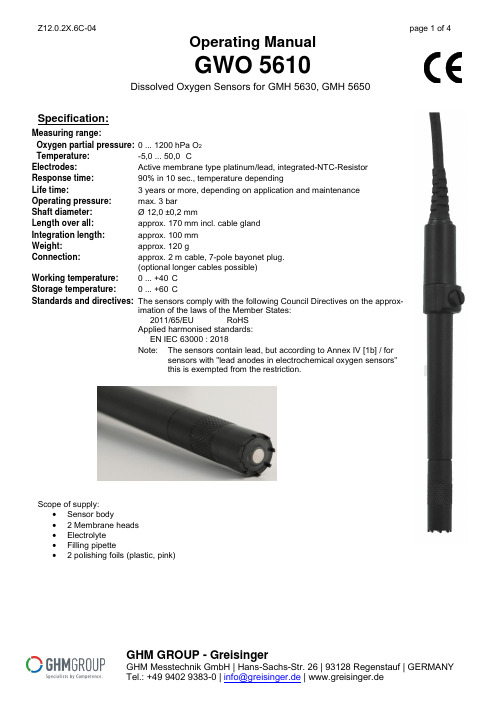
Operating ManualGWO 5610Dissolved Oxygen Sensors for GMH 5630, GMH 5650Specification:Measuring range:Oxygen partial pressure: 0 ... 1200 hPa O2Temperature:-5,0 ... 50,0 °CElectrodes:Active membrane type platinum/lead, integrated-NTC-ResistorResponse time:90% in 10 sec., temperature dependingLife time: 3 years or more, depending on application and maintenanceOperating pressure:max. 3 barShaft diameter:Ø 12,0 ±0,2 mmLength over all:approx. 170 mm incl. cable glandIntegration length:approx. 100 mmWeight:approx. 120 gConnection:approx. 2 m cable, 7-pole bayonet plug.(optional longer cables possible)Working temperature:0 ... +40°CStorage temperature: 0 ... +60°CStandards and directives:The sensors comply with the following Council Directives on the approx-imation of the laws of the Member States:2011/65/EU RoHSApplied harmonised standards:EN IEC 63000 : 2018Note: The sensors contain lead, but according to Annex IV [1b] / forsensors with "lead anodes in electrochemical oxygen sensors"this is exempted from the restriction.Scope of supply:∙Sensor body∙ 2 Membrane heads∙Electrolyte∙Filling pipette∙ 2 polishing foils (plastic, pink)GHM GROUP - GreisingerGHM Messtechnik GmbH | Hans-Sachs-Str. 26 | 93128 Regenstauf | GERMANYTel.: +49 9402 9383-0 | | www.greisinger.deDesign of Sensor GWO 5610Lifetime:At the end of the Lifetime, the signal of the sensor is dropping rapidly. The sensor evaluation in % therefore e can only be taken as a relative measure. An evaluation of 70% does not mean that 70% of lifetime is left, but that the electrode signal has 70% of a good state reference.Note: The sensor state evaluation will be stored after a successful calibration of the oxygen sensorThe nominal lifetime may be reduced due to the application. Negative effecting are:- Extreme storage and operation temperature- D irty water during measuring- Mechanical stress to sensor membrane- Dry storage of filled sensor- Permanent use at higher CO 2-concentrationsMounting/Operation Position:The optimum position is with sensor membrane pointing downwards.Measuring Precision: The precision can be influenced due to:- To less flow- Water and sensor temperature have to be the same, most exact measuring is done, when calibrated at measuring temperature.Generalfilling hole shaft membrane head platinum elec-trode protective flask The oxygen sensor is an active sensor. It consists of a platinum cathode, a lead an-ode and potassium hydroxide (KOH) as an electrolyte. If oxygen is present, it is re-duced on the platinum cathode and the sensor delivers a signal. If no oxygen is pre-sent, no signal is delivered. The anode is consumed by the oxygen measurement.The sensor ages. Furthermore, the sensor loses liquid through the permeable mem-brane, in particular, when it is stored in dry air. Therefore, it should be checked andmaintained regularly and replaced as necessary. (p.r.t. sensor maintenance)Make it a rule to always store the electrode in a humid environment- in the storage flask filled with water or- in another container filled with waterIf electrode has not been used for some time, clean membrane with softcloth and remove deposits, if any (algae, bacteria etc.).Attention: The membrane is delicate – if damaged, caustic electrolytegets lost and the sensor shows wrong signal. DesignThe electrode housing is made of ABS. With the exception of the electrode shaft all parts need to be maintained regularly and be replaced if necessary. o Protective flask : The protective flask is used to moisten the membrane. This prolongs service life of the electrode. The protective flask contains water. Attention ! Use water only; never use potassium chloride (KCI); this is only re-quired for storage of pH-electrode.o Membrane head : the membrane head is covered with a Teflon membrane. It will be filled with KOH electrolyte and screwed onto the electrode shaft (no airbubbles). Damages in the membrane, large air bubbles or air bubble rings in the membrane head will result in erroneous measurements. This may also be the rea-son for errors in the calibration.The membrane head (GWOK 02) is a spare part and can be ordered individually. o Filling hole : If the electrode is used at high temperatures or if it has been stored without its protective flask for a longer period of time, some electrolyte will be lostdue to evaporation. Please refer to Refilling description below.DANGER Attention when working with electrolyte: The electrolyte is caustic! (strong base, KOH) Avoid contact to skin, protect Your eyes !Visible Residues in the Inner of Membrane Head:As a reaction product in operation, there will be lead oxide (red and brown – from the reaction with oxygen) and lead carbonate (white – from the reaction of carbon dioxide) in the inner of the sensor.These substances may accumulate visibly at the membrane, but usually have now negative effect on the operability. Within a maintenance cycle the residues can be washed off the membrane nearly completely.Significant deposits on the membrane and matt platinum electrode.Deposits already have an effect on the measurement.=> Carry out maintenance to remove these.Slight deposits on the edge of the electrode, predominantly blank platinum elec-trode.No significant influences on the measurement to be expected.=> Maintenance not absolutely necessary.Deposits on the membrane, bare platinum electrode.=> no maintenance required.Polished platinum electrode during maintenance.Before screwing the membrane head on sensor body again they should be washed off, to avoid them getting in be-tween platinum cathode and membrane.A fast occurrence shortly after first filling or an unusual high amount of them (e.g. within some days) may be a sign of air in the sensor – either because of incorrect filling (bubbles), not sufficiently closing membrane head or filling screw or a leaking membrane.First start of operation of dry sensor GWO 5610 / Refilling of GWO 5610The GWO 5610 can be delivered dry as an option. Therefore the sensor is easily storable over a long time.The sensor has to be filled timely towards the measuring. After filling a time of ~ 2 hours has to be considered, until the sensor has stabilized.Wear suitable gloves*) and protect your eyes with safety goggles when filling the electrolyte!Do not touch the electrolyte with bare skin, if there was contact rinse sufficiently with water.Material:∙Sensor GWO 5610 with membrane head∙Filling-pipette∙Electrolyte KOH∙Flat blade screw driver∙Paper towel∙Suitable gloves *), safety goggles∙Wash basinFirst Filling:∙Check membrane head GWOK 02: is it in good state? Is Mem-brane undamaged?∙Open filling screw∙Fill pipette with KOH∙First fill the membrane head up to ¾ of its height, screw onmembrane head tightly, rinse excess KOH with water.∙Then carefully fill the sensor, try to flick at the shaft from time totime, helping air bubbles coming out. In sum the sensor fillingtakes around 5 ml.∙If there are no more air bubbles and the filling hole is full, closewith filling screw.∙Rinse excess KOH with waterFigure: Filling with pipette ∙Turn sensor upwards: Are air bubbles visible below the mem-brane? If so: Refill once again.∙Wait approximately 2 hours for the sensor to stabilize, afterwards calibrate the sensor – the electrode state evaluation should deliver 100%.*) suitable gloves: Acc. to DIN EN 420, e.g. natural latex, natural rubber, butyl rubber, nitrile rubber,polychloroprene, fluorinated rubber.Sensor Maintenance of GWO 5610If the sensor can no more be calibrated or only unstable values are displayed, it has to be maintained or even or the membrane head has to be exchanged.Wear suitable gloves*) when filling the electrolyte! Do not touch the electrolyte with bare skin. If there was contact rinse sufficiently with water.Material:∙Sensor GWO 5610, eventually spare membrane head GWOK 02∙Filling pipette∙Electrolyte KOH∙Flat blade screw driver∙Paper towel∙Polishing foil (pink)∙Suitable gloves *), Safety goggles∙Wash basinMaintenance is basically the same as the first filling, but first the membrane head is unscrewed and the old electro-lyte is removed.Unscrew the membrane head and the refill opening - Attention! Old electrolyte will now leak out!If the membrane is undamaged and free of deposits, the membrane head can be used again.The platinum electrode must be bright and free of deposits!Wipe off existing deposits from the platinum electrode with a cloth, if necessary polish the electrode using the pink polishing foil.The filling of the sensor is like described bevor.Hints for Operation:a.) Treat device and sensor carefully. Use only in accordance with above specification. (do not throw, hit againstetc.). Protect plug and socket from soiling.b.) The electrode are only suitable for the devices GMH5630, 5650. Unsuitable devices may lead to the destructionof the measuring device and the oxygen sensor.c.) A protective cap, such as GSKA 3600 in plastic or GSKA 3610 in red bronze is recommended for protection ofthe membrane, e.g. for use in bodies of water.Safety guidelines:This device has been designed and tested in accordance with the safety regulations for electronic devices. However, its trouble-free operation and reliability cannot be guaranteed unless the standard safety measures and special safety advises given in this manual will be adhered to when using the device.1. Trouble-free operation and reliability of the device can only be guaranteed if the device is not subjected to anyother climatic conditions than those stated under "Specification".2. Do not use these products as safety or emergency stop devices or in any other application wherefailure of the product could result in personal injury or material damage.Failure to comply with these instructions could result in death or serious injury and material dam-age.3. Attention, caustic! The sensor contains KOH electrolyte (Potassium Hydroxide).KOH may cause burns!Avoid the contact to leaking liquid!When there was contact:- to skin: immediately flush with water for several minutes- to clothing: take of affected clothing.- to the eyes flush with water for several minutes, get medical aid.In case of ingestion:Drink plenty of water immediately, do not induce vomiting! Get medical aid.Disposal instructionsThe electrode contains lead and corrosive electrolytic liquid and must not be disposed of in theresidual waste bin. Do not dispose of together with batteries, risk of explosion!Return it to us, freight prepaid. We will then arrange for the proper and environmentally-friendlydisposal.Private end users in Germany have the possibility of dropping off the product at the municipalcollection centre。
氧传感器技术手册

氧传感器使用说明书 (第一版)适用零件号:25327985 253599081.概述氧传感器是现代发动机管理系统中必不可少的重要零部件。
它是一种利用电化学工作原理发展出来的电器元件。
氧传感器在现代发动机管理系统的配置机构中被用于探测汽车发动机所排出的燃烧废气中氧的含量,借以判定发动机实时燃油供给空气燃料混合比的实际状态,并通过自身产生的电器反应信号反馈给发动机电子控制模块(ECM),以作为系统燃油管理系统的闭环燃油修正补偿控制的重要依据,使燃油管理子系统能够更加精确地控制调整发动机各种工作状态下的空气燃料混合比;并在绝大多数工况下使系统保持在理想空燃比工作状态,以便获得更加优良的汽车排放控制特性和燃油经济性。
氧传感器的输出信号为0 ~ 1V的交变电压信号。
传感器可根据发动机所排燃烧气中氧的含量高低自动感应和探测并向发动机电子控制模块输出这一高低变化的电压信号。
现代发动机管理系统采用的氧传感器有两种主要类型:非加热型氧传感器和加热型氧传感器。
装配在发动机排气歧管上的氧传感器,由于可以利用发动机所排出燃烧废气的余热进行快速加热,故可使用价格低廉的非加热型氧传感器;当氧传感器的安装位置受到整车布置限制,氧传感器距离发动机排气歧管出口较远时,由于不能利用发动机燃烧废气对于传感器迅速加热,此时必然需要采用加热式氧传感器。
加热式氧传感器的内部设计有热敏电加热元件,可利用系统供电电压强制使氧传感器加速预热,促使其快速起燃,及早实现系统的闭环燃油管理控制。
2. 工作原理德尔福公司生产的氧传感器是采用氧化锆元件作为传感器的基础元件。
氧化锆元件是一种通体充满无数微孔的陶瓷基础元件外面镀有氧化锆涂层,该涂层外测暴露于发动机燃烧废气之中;涂层的内侧透过含微孔的陶瓷元件与大气相通。
集中在氧化锆内外两侧电极之间氧含量的差别形成的微分电压信号。
当氧化锆元件被电流加热或被流经传感器的发动机燃烧废气加热所激活,空气经过通体充满无数微孔的陶瓷基础元件进入氧化锆元件的内电极,而燃烧废气流经氧化锆的外电极。
ME3-O2电化学氧气传感器

技术参数 0—25%vol 30%vol 2年 0.15±0.05 mA(空气中) ﹣20℃~+50℃ 标准大气压±10﹪ ≤15S 0—99﹪RH 无凝结 <2﹪ 100Ω <2﹪输出值
A━左视图 B━仰视图 C━俯视图
以诚为本、信守承诺
创造完美、服务社会 2008.03.13
输出电 压(mV) 信号输 出(mV)
ME3-O2 电化学式气敏元件产品说明书
以诚为本、信守承诺
创造完美、服务社会 2008.03.13
ME3-O2 型氧传感器是根据电化学原电池的原理工作, 利用待测气体在原电池中阴极上的电化学还原和阳极的 氧化过程,产生电流,并且待测气体电化学反应所产生的 电流与其浓度成正比并遵循法拉第定律。这样,通过测定 电流的大小就可以确定待测气体的浓度。
特点
。低功耗
。
高
精
度
元件外形结构
。高灵敏度
。线性范围宽
。抗干扰能力强
。优异的重复性和稳定性
应用
广泛适合工业、矿下及环保中氧气的检测。
18697315156
QQ:2627662407
W
无
C
技术指标
项目 量程 最大测量限 检测寿命 灵敏度 温度范围 压力范围 响应时间(T90) 湿度范围 稳定性(/月) 负载电阻(推荐) 重复性
高低温传感器零点变化
1.06 ME3-O2温度特性
1.04
1.02
1
0.98
0.96
0.94
0.92
0.9
-40
-20
0
20
温度(℃)
40
60
以诚为本、信守承诺
创造完美、服务社会 2008.03.13
氧传感器说明书(国华元融)
3. 工作原理
系统原理方框见下图。24V 直流电源输入后,一路用于产生系统内部的工作电压, 一路用于氧探头的加热。
3
国华元融
经过一定时间的上电预热,氧探头中的二氧化锆,在达到 700℃的工作温度后,由 绝缘体成为氧离子导体。动态氧传感器独特的双锆盘结构,使氧探头、信号放大器、 逻辑监测模块和离子泵形成稳定的负反馈回路。当温度稳定时,负反馈的脉冲输出信 号的周期时间,与氧量成线性正比。
5.2.2. 人工校准 ........................................................................................... 8
6. 串口工作模式....................................................................................................... 8
5.2.Biblioteka 校准 ............................................................................................................ 8
5.2.1. 自动校准 ........................................................................................... 8
模拟信号输出可以通过内部跳线选择 0~10V 电压信号或 4~20mA 电流信号。串 口工作模式主要推荐 RS485 总线工作模式。UART 是单片机的串口不经过 RS485 芯片 的直接输出,两者在软件上的使用是相同的,所有操作均为半双工模式。
O2 传感器 4100 e 说明书

Instruction manual O2Transmitter 4100 eOrder number: 52 121 114ContentsMettler-Toledo GmbH, Process Analytics, Industrie Nord,CH-8902 Urdorf, Tel. (01) 736 26 36Subject to technical changes. Mettler-Toledo GmbH, 10/03.WarrantyDefects occurring within 1 year from delivery date shall be remedied free of charge at our plant (carriage and insurance paid by sender).Subject to change without noticeDisposal (Directive 2002/96/EC of January 27, 2003)Please observe the applicable local or national regulations concerning the disposal of “waste electrical and electronic equipment”.ContentsSafety information Array Be sure to read and observe the following instruc-tions!The device has been designed in accordance with the state ofthe art and complying with the applicable safety regulations.When operating the device, certain conditions may neverthe-less lead to danger for the operator or damage to the device.Caution!Commissioning may only be carried out by trained experts.Whenever it is likely that protection has been impaired, thedevice shall be made inoperative and secured against unintend-ed operation.The protection is likely to be impaired if, for example:•the device shows visible damage•the device fails to perform the intended measurements•after prolonged storage at temperatures above 70 °C•after severe transport stressesBefore recommissioning the device, a professional routine testin accordance with EN 61010-1 must be performed. This testshould be carried out by the manufacturer.Intended useThe O2Transmitter 4100 e is used for dissolved oxygen and tem-perature measurement in biotechnology, pharmaceutical industry, as well as in the field of environment, food processing, and sewage treatment.The rugged molded enclosure can be wall or pipe mounted or fixed into a control panel.The protective hood provides additional protection against direct weather exposure and mechanical damage.The Transmitter has been designed for application with ampero-metric sensors of the InPro6000 ... InPro6800 Series. TrademarksThe following names are registered trademarks. For practical rea-sons they are shown without trademark symbol in this manual. InPro®EasyClean®EC Declaration of conformityOverview of O 2Transmitter 4100 eDo not connect!CathodeGuardAnodeReference electrode RTDRTDshieldHOLD HOLD/CONTROL CONTROL+ Output 1- Output 1/2+ Output 2Relay 1Relay 1/2Relay 2AlarmAlarmClean Clean Power PowerPackage contentsCheck the shipment for transport damage and completeness. The package should contain:• Front unit• Lower case• Bag containing small parts• Instruction manual• Specific test reportAssemblyFig.: Pipe-mount kitPipe mounting, panel mountingInstallation and connectionCaution!•Installation may only be carried out by trained experts in accordance with this instruction manual and as per applicable local and national codes.•Be sure to observe the technical specifications and input ratings.•Be sure not to notch the conductor when stripping the insulation.•Before connecting the device to the power supply, make sure that its voltage lies within the range 20.5 to 253 V AC/DC.•When commissioning, a complete configuration must be carried out by the system administrator.The terminals are suitable for single wires and flexible leads upto 2.5 mm2(AWG 14)Warning!Additional safety precautions have to be taken for applications in hazardous locations to CSA (CLI DIV2 GPA,B,C,D T4, Ex nA IIC T4)!(See Pg 93.)Protective wiring of switching contactsRelay contacts are subjected to electrical erosion. Especially with inductive and capacitive loads, the service life of the con-tacts will be reduced. For suppression of sparks and arcing,components such as RC combinations, nonlinear resistors,series resistors and diodes should be used.Protective wiringA: DC application with inductive loadB: AC/DC applications with capacitive load C: Connection of incandescent lampsA1Inductive loadA2Free-wheeling diode, e.g. 1N4007 (Observe polarity)A3ContactB1Capacitive loadB2Resistor, e.g. 8 Ohms/1 W at 24 V / 0.3 A B3ContactC1Incandescent lamp, max 60 W / 230 V , 30 W / 115 V C3ContactWarning!Make sure that the maximum ratings of the relay contacts are not exceeded even during switching!Typical protective wiring measuresProtective wiringUser interface, displayDisplayOperation: KeypadSensocheck, Sensoface sensor monitoringSensocheck continuously monitors the sensor and leads.Sensocheck can be switched off (Configuration, Pg 46).Safety featuresMode codesThe mode codes allow fast access to all functions CalibrationOverview of configuration stepsNote:The Transmitter 4100 e has a device a resolution of 0.01 ppm. For the sensor type B, we recommend the O2Transmitter 4100ppb with a device resolution of 0.001 ppm.Polarization voltage. Process pressure. Salt correction.Two complete parameter sets are stored in the EEPROM. As delivered, the two sets are identical but can be edited. Note:Fill in your configuration data on the following pages.Default settings of parameter setsCode. Parameter Setting o1. Sensor type ________________________o1. %, mg/l, ppm ________________________o1. 0/4-20 mA________________________o1. Current beginning ________________________o1. Current end ________________________o1. Filter time ________________________o1. 22mA signal ________________________o1. Hold behavior ________________________o1. Fix current ________________________o2. Unit °C / °F ________________________o2. Temp probe ________________________o2. 0/4...20mA________________________o2. Current beginning ________________________o2. Current end ________________________o2. Filter time ________________________o2. 22mA signal ________________________o2. Hold behavior ________________________o2. Fix current________________________Co. Polarization voltage ________________________Co. Pressure unit ________________________Co. Pressure ________________________Co. Salinity ________________________CA. Cal mode ________________________CA. Cal interval ________________________AL. Sensocheck ________________________AL. Alarm delay ________________________AL. LED Hold________________________Parameter set – user settingsCode. Parameter Setting rL. Relay function ________________________L1. Contact function ________________________L1. Contact response ________________________L1. Switching point ________________________L1. Hysteresis ________________________L1. Delay________________________L2. Contact function ________________________L2. Contact response ________________________L2. Switching point ________________________L2. Hysteresis ________________________L2. Delay________________________Ct. Setpoint ________________________Ct. Neutral zone ________________________Ct. P action ________________________Ct. I action ________________________Ct. D action________________________Ct. PLC/PFC controller ________________________Ct. Pulse length ________________________Ct. Pulse frequency ________________________Ct. Hold behavior ________________________Pb. Probe selection ________________________Pb. Rinsing interval ________________________Pb. Rinse duration ________________________Pb. Contact type ________________________Pb. Cleaning interval________________________Pb. Lock cleaning interval________________________It is always recommended to calibrate in air.Compared to water, air is a calibration medium which is easy to handle, stable, and thus safe. In the most cases, however, the sensor must be dismounted for a calibration in air.When dealing with biotechnological processes which require sterile conditions, the sensor cannot be removed for calibration. Here, calibration must be performed with aeration directly in the process medium (e.g. after sterilization).The calibration procedures for these two common applications are described on the following pages. Of course, other combina-tions of process variable and calibration mode are possible.Note:When a 2-point calibration is required, the zero point calibration should be performed prior to saturation or concentration cali-bration, resp.All calibration procedures must be performed by trainedpersonnel.Zero point calibrationNote:In Hold mode the controller output acts as configured (Y = const. or Y = 0).50 %X w10 / (1.00)20 / (2.00)30 / (3.00)40 / (4.00)50 / (5.00) ControlleroutputYProportional action (Gradient K C[%])Neutral zone (Y=0)Tolerated deviation from setpoint.The setting “010%”, for example, permits a deviation of ±5 % from the desired value without activating the controller.Pulse length / pulse frequency controllerPulse length controller (PLC)The pulse length controller is used to operate a valve as an actuator. It switches the contact on for a time that depends on the controller output. The period is constant. A minimum ON time of 0.5 sec is maintained even if the controller output takes corresponding values.Pulse frequency controller (PFC)The pulse frequency controller is used to operate a frequency-controlled actuator. It varies the frequency with which the contacts are switched on. The maximum pulse frequency [pulses/min] can be defined. It depends on the actuator.The Contact ON time is constant. It is automatically calculated from the user-defined maximum pulse frequency:Output signal (switching contact) of pulse frequency controllerOutput signal (switching contact) of pulse length controllerOperation with automatic cleaning system“EasyClean” is a separate automatic cleaning system. The cleaning cycle is activated according to the cleaning interval defined during configuration (Pg 55).Calibration error messagesNoteThe worsening of a Sensoface criterion leads to the devaluation of the Sensoface indicator (Smiley becomes “sad”). An improvement of the Sensoface indicator can only take place after calibration or removal of a sensor defect.SensocheckContinuously monitors the sensor and lines for short circuits or open circuits. Critical values make the Sensoface “sad” and the corresponding icon flashes:The Sensocheck message is also output as error messageErr33. The alarm contact is active, the red LED is lighted, out-put current 1 is set to 22 mA (when configured corresponding-ly). Sensocheck can be switched off during configuration (then Sensoface is also disabled). Exception: After a calibration aAppendixProduct line and accessoriesDevices Order No. O2Transmitter 4100 e52 121 103 Mounting accessoriesPipe-mount kit52 120 741 Panel-mount kit52 120 740 Protective hood52 120 739 SensorsMettler-Toledo GmbH, Process Analytics offers a wide range of sensors for the following fields of applications:- Chemical process industry- Pharmaceutical industry- Food and beverage industry- Water/waste-waterFor more information concerning our sensors and housings program, please refer to .DO input Sensor Type A: InPro6000 – 6800Sensor Type B:InPro6900Measuring current-2 to 1800 nA,Resolution 0.05nA(with Vpol = 800 mV and Vref = 200 mV)Saturation (-10 to 80 °C)0 to 500 %Meas. error1,2,30.5 % meas.val. + 0.5 %Concentration (-10 to 80 °C)0.00 to 50.00 mg/l0.00 to 50.00 ppmMeas. error1,2,30.5 % meas.val. + 0.05 mg/lor 0.05 ppmAdm. guard current≤20 µAPolarization voltage*0 to 1000 mV,Process pressure *0.000 to 9.999 bars(to 999.9 kPa / to 145.0 psi)Salt correction *00.00 to 45.00 g/kgSensor standardizationOperating modes *DO saturation (automatic)DO concentration (automatic)Product calibrationZero point calibrationCalibration range Zero point±2 nASensor Type A Slope25 to 130 nA(at 25 °C, 1013 mbars)Calibration range Zero point±2 nASensor Type B Slope200 to 550 nA(at 25 °C, 1013 mbars)Calibration timer *0000 to 9999 hPressure correction *0.000 to 9.999 bars / 999.9 kPa / 145.0 psiSensocheck Monitoring for short circuits / open circuits (can be disabled)Sensoface Provides information on the sensor conditionEvaluation of zero/slope, response,calibration interval, Sensocheck Temperature NTC 22 kOhms / NTC 30 kOhms, selectableinput2-wire connection, adjustableMeasurement range-20.0 to +150.0 °C / -4 to +302 °FAdjustment range10 KResolution0.1 °C / 1 °FMeas. error1,2,3< 0.5 K (<1 K at > 100°C)HOLD input Galv. separated (OPTO coupler)Function Switches Transmitter to HOLD modeSwitching voltage Inactive0 to 2 V (AC/DC)Active10 to 30 V (AC/DC) CONTROL input Galv. separated (OPTO coupler)Function Control input for automatic cleaning system Switching voltage Inactive0 to 2 V (AC/DC)Active10 to 30 V (AC/DC) Output 10/4 to 20 mA, max. 10 V, floating(galv. connected to output 2)Process variable *DO saturation/DO concentrationOverrange *22 mA in the case of error messagesOutput filter *Low-pass, filter time constant 0 to 120 sMeas. error 1< 0.3 % current value + 0.05 mAStart/end of scale Configurable within selected rangeAdm. span 5 to 500 % / 0.5 to 50 mg/l (ppm)Output 20/4 to 20 mA, max. 10 V, floating(galv. connected to output 1)Process variable TemperatureOverrange *22 mA in case of temp error messagesOutput filter *Low-pass, filter time constant 0 to 120 sMeas. error 1< 0.3 % current value + 0.05 mAStart/end of scale*-20 to +150 °C / -4 to +302 °FAdm. span 20 to 170 K (68 to 338 °F)Alarm contact Relay contact, floatingContact ratings AC< 250 V / < 3 A / < 750 VADC< 30 V / < 3 A / < 90 WContact response N/C (fail-safe type)Response delay *0000 to 0600 sLimit values Output via relay contacts R1, R2Contacts R1, R2 floating but inter-connected Contact ratings AC< 250 V / < 3 A / < 750 VADC< 30 V / < 3 A / < 90 WContact response*N/C or N/OResponse delay *0000 to 0600 sSwitching points*Within selected rangeHysteresis*000.0 to 050.0 % / 00.00 to 05.00 mg/l (ppm)PID Output via relay contacts R1, R2process controller(Relay R1: below setpoint,Relay R2: above setpoint)Setpoint specification*0 to 500 % / 0.00 to 50.00 mg/l (ppm)Neutral zone*000.0 to 050.0 % / 00.00 to 05.00 mg/l (ppm)P-action component*Controller gain Kp: 0010 to 9999 %I-action component*Reset time Tr:0000 to 9999 s(0000 s = no integral action) D-action component*Rate time Td: 0000 to 9999 s(0000 s = no derivative action) Controller type*Pulse length controller or pulse frequency controller Pulse period*0001 to 0600 s, min. ON time 0.5 s(pulse length controller)Max. pulse frequency*0001 to 0180 min-1(pulse frequency controller)Cleaning function*Relay contact, floating, for controlling a simple rinsingsystem or an automatic cleaning system (EasyClean) Contact ratings AC< 250 V / < 3 A / < 750 VADC< 30 V / < 3 A / < 90 WContact response*N/C or N/OInterval *000.0 ... 999.9 h(000.0 h = cleaning function switched off)Rinse duration*0000 ... 1999 sDisplay LC display, 7-segment with iconsMain display Character height 17 mm, unit symbols 10 mm Secondary display Character height 10 mm, unit symbols 7 mmSensoface 3 status indicators (friendly, neutral, sad Smiley)Mode indicators 5 status bars“meas”, “cal”, “alarm”, “cleaning”, “config”18 further icons for configurationand messagesAlarm indication Red alarm LED in case of alarm or HOLD (user defined) Keypad 5 keysService functionsCurrent source Current specifiable for output 1 and 2 (00.00 to 22.00 mA) Manual controller Controller output entered directly (start of control process) Device self-test Automatic memory test (RAM, FLASH, EEPROM)Display test Display of all segmentsLast Error Display of last error occurredSensor monitor Display of direct, uncorrected sensor signalRelay test Manual control of the four switching contactsParameter sets Two selectable parameter sets for differentapplicationsData retention Parameters and calibration data > 10 years (EEPROM)Protection against Protective separation of all extra-low-voltage circuits against electrical shock mains by double insulation as per EN 61010-1Power supply24 (-15%) to 230 V AC/DC (+10%); approx. 5 VA, 2.5 WAC: 45 to 65 Hz; Overvoltage category II, Class IINominal operating conditionsAmbient temperature-20 to +55 °CTransport/Storage temp.-20 to +70 °CRelative humidity 10 to 95 % not condensingPower supply24 (-15%) to 230 V AC/DC (+10%)Frequency for AC45 to 65 HzEMC EN 61326Emitted interference Class B (residential environment)Class A for mains supply > 60 V DCImmunity tointerference IndustrialenvironmentExplosion protectionFM: NI Class I Div 2 Group A, B, C & D,T4T a = 55 °C; T ype 2NI Class I Zone 2Group IIC,T4 T a = 55°C; T ype 2CSA:Class I Div 2 Groups A, B, C and D,T4Ex nA IIC T4Enclosure Molded enclosure made of PBT (polybutylene terephtalate) Color Bluish gray RAL 7031Assembly• Wall mounting• Pipe mounting: dia 40 to 60 mm, 30 to 45 mm• Panel mounting, cutout to DIN 43 700Sealed against panelDimensions H 144 mm, B 144 mm, T 105 mmIngress protection IP 65 / NEMA 4XCable glands 3 breakthroughs for cable glands M20x1.52 breakthroughs for NPT 1/2 “orRigid Metallic ConduitWeight Approx. 1 kg*) User-defined) To IEC 746 Part 1, at nominal operating conditions) ±1 count) Plus sensor errorExplosion protectionWarnings and notesto ensure safe operation2-point calibration . . . . . . . . . . . . . . . . . . . . . . . . . . . . . .6122 mA signal for error message . . . . . . . . . . . . . .37, 43, 78Accessories . . . . . . . . . . . . . . . . . . . . . . . . . . . . . . . . . . . .85Alarm settings . . . . . . . . . . . . . . . . . . . . . . . . . . . . . . . . . .46Alarm contact . . . . . . . . . . . . . . . . . . . . . . . . .46, 88, 78Alarm delay . . . . . . . . . . . . . . . . . . . . . . . . . . . . . . . . . 47Error messages . . . . . . . . . . . . . . . . . . . . . . . . . . . . . . .78Operating states . . . . . . . . . . . . . . . . . . . . . . . . . . . . . .80Assembly . . . . . . . . . . . . . . . . . . . . . . . . . . . . . . . . . . . . .10Cal timer . . . . . . . . . . . . . . . . . . . . . . . . . . . . . . . . . . . . . .47Calibration . . . . . . . . . . . . . . . . . . . . . . . . . . . . . . . . . . . .61Calibration to concentration (Conc) . . . . . . . . . . . . . . . .64Calibration to saturation (SAT) . . . . . . . . . . . . . . . . . . . .62Display of calibration data . . . . . . . . . . . . . . . . . . . . . . .71Specify calibration mode . . . . . . . . . . . . . . . . . . . . . . . .47Cleaning system . . . . . . . . . . . . . . . . . . . . . . . . . . . . . . . .77Configuration . . . . . . . . . . . . . . . . . . . . . . . . . . . . . . . .54Lock cleaning interval . . . . . . . . . . . . . . . . . . . . . . . . . .54Configuration . . . . . . . . . . . . . . . . . . . . . . . . . . . . . . . . . .26Configuration steps . . . . . . . . . . . . . . . . . . . . . . . . . . . .28Menu structure . . . . . . . . . . . . . . . . . . . . . . . . . . . . . . .27Configuration: Alarm settings . . . . . . . . . . . . . . . . . . . . . .46Alarm delay . . . . . . . . . . . . . . . . . . . . . . . . . . . . . . . . . .47LED in HOLD mode . . . . . . . . . . . . . . . . . . . . . . . . . . . .47Sensocheck . . . . . . . . . . . . . . . . . . . . . . . . . . . . . . . . . .47Configuration: Correction . . . . . . . . . . . . . . . . . . . . . . . . .44Polarization voltage . . . . . . . . . . . . . . . . . . . . . . . . . . . .44Process pressure . . . . . . . . . . . . . . . . . . . . . . . . . . . . . .44Salt correction . . . . . . . . . . . . . . . . . . . . . . . . . . . . . . . .44Configuration: Calibration mode . . . . . . . . . . . . . . . . . . .46Cal timer interval . . . . . . . . . . . . . . . . . . . . . . . . . . . . . .47Configuration: Controller . . . . . . . . . . . . . . . . . . . . . . . . .52IndexConfiguration: Limit function . . . . . . . . . . . . . . . . . . . . . .48Settings for relay 1 . . . . . . . . . . . . . . . . . . . . . . . . . . . .48Settings for relay 2 . . . . . . . . . . . . . . . . . . . . . . . . . . . .50Use of relays . . . . . . . . . . . . . . . . . . . . . . . . . . . . . . . . .49Configuration: Output 1 . . . . . . . . . . . . . . . . . . . . . . . . . .30Measurement procedure . . . . . . . . . . . . . . . . . . . . . . . .30Output current during Error . . . . . . . . . . . . . . . . . . . . . .36Output current range . . . . . . . . . . . . . . . . . . . . . . . . . .32Output signal during HOLD . . . . . . . . . . . . . . . . . . . . . .37Select sensor type . . . . . . . . . . . . . . . . . . . . . . . . . . . . .30Time constant of output filter . . . . . . . . . . . . . . . . . . . . .34Configuration: Output 2 . . . . . . . . . . . . . . . . . . . . . . . . . .38Output current during HOLD . . . . . . . . . . . . . . . . . . . . .42Set output current range . . . . . . . . . . . . . . . . . . . . . . . .39Temperature error . . . . . . . . . . . . . . . . . . . . . . . . . . . . .42Temperature probe . . . . . . . . . . . . . . . . . . . . . . . . . . . .39Temperature unit . . . . . . . . . . . . . . . . . . . . . . . . . . . . . .38Time constant of output filter . . . . . . . . . . . . . . . . . . . .40Configuration: Rinsing and calibration probes . . . . . . . . . .54Control drawing . . . . . . . . . . . . . . . . . . . . . . . . . . . . .94, 96Controller . . . . . . . . . . . . . . . . . . . . . . . . . . . . . . . . . . . . .74Configuration . . . . . . . . . . . . . . . . . . . . . . . . . . . . . . . .62Controller equations . . . . . . . . . . . . . . . . . . . . . . . . . . .75Controller test . . . . . . . . . . . . . . . . . . . . . . . . . . . . . . . .73Pulse length / pulse frequency controller . . . . . . . . . . . .74Controller: behavior during HOLD . . . . . . . . . . . . . . . . .53Current source 1/2 . . . . . . . . . . . . . . . . . . . . . . . . . . . . . .72Diagnostics functions . . . . . . . . . . . . . . . . . . . . . . . . . . . .71Controller test . . . . . . . . . . . . . . . . . . . . . . . . . . . . . . . .73Display of calibration data . . . . . . . . . . . . . . . . . . . . . . .71Display of last error message . . . . . . . . . . . . . . . . . . . . .71Display of output currents . . . . . . . . . . . . . . . . . . . . . . .71Display of sensor current . . . . . . . . . . . . . . . . . . . . . . . .71。
- 1、下载文档前请自行甄别文档内容的完整性,平台不提供额外的编辑、内容补充、找答案等附加服务。
- 2、"仅部分预览"的文档,不可在线预览部分如存在完整性等问题,可反馈申请退款(可完整预览的文档不适用该条件!)。
- 3、如文档侵犯您的权益,请联系客服反馈,我们会尽快为您处理(人工客服工作时间:9:00-18:30)。
氧传感器使用说明书(详细版)-CAL-FENGHAI.-(YICAI)-Company One11.概述氧传感器是现代发动机管理系统中必不可少的重要零部件。
它用于探测汽车发动机排气管中燃烧废气中氧的含量,借以判定发动机实时空燃比状态。
根据氧浓度的不同,传感器将输出高低不同的电压信号给发动机电子控制模块(ECM),作为系统闭环燃油修正补偿控制的重要依据。
由于氧传感器的应用,发动机能在绝大多数工况下工作在理想空燃比状态,从而获得良好的排放特性和燃油经济性。
本公司加热式氧传感器尺寸小巧,起燃迅速,可使发动机管理系统及早实现系统的闭环燃油管理控制。
图一氧传感器外观2.工作原理氧传感器采用平板结构多层氧化锆陶瓷作为核心元件。
3.结构特征本公司生产的现代发动机管理系统配套用氧传感器的主要特点为:全球统一设计,全球采购系统可保障全球产品性能的一致性;也可根据客户图纸要求制作,满足客户需求的产品氧传感器插接器具备防水功能起燃时间极短,反应迅速通用化接口结构设计,易于满足不同客户需要超强低温适应性能超强抗杂质中毒性能设计可预防表面化合物烧结采用不锈钢材料导线,工作可靠具有防错设计,便于应用单独接地设计,系统工作稳定可靠4. 性能参数和技术规格(在温度450℃条件下的发动机测功机上的实测数值)空燃比为浓的电压信号: >750毫伏 空燃比为稀的电压信号: <120毫伏 450℃时,空燃比浓变稀的相应时间: <150毫秒 450℃时,空燃比稀变浓的相应时间: <65毫秒 锆元件活化时间 <12秒 加热元件电阻(21℃) ±欧姆 加热元件电流: ±安培 加热元件功率: 瓦 内部电阻: <500欧姆 外接电压(接ECM 控制器): 伏特 氧传感器信号传输线束线径要求: 氧传感器典型配套接插器由我公司生产;也可采用其代用品。
氧传感器接线端子及导线定义,详见表1和图3。
也可根据客户提供的外观要求制作。
5. 产品考核要求氧传感器满足以下性能、耐久及环境测试要求。
表1 接线端子定义 接线端子编号接线端子定义 连接导线颜色A 信号输出低电平 灰色B 信号输出高电平 黑色C 加热元件负极白色 D加热元件正极白色A B C D图3 接线端子图示发动机极限温度试验对氧传感器进行500小时高温循环耐久试验(最高温度为930℃),试验后,氧传感器性能符合规定要求。
浸没试验对氧传感器进行特定条件的水浸泡循环试验(不包括插接件和感应头/下护罩),试验后,氧传感器性能符合规定要求。
线束抗拉力抗疲劳试验氧传感器线束能够分别承受至少1分钟的三个方向最小100牛顿拉力试验,试验后性能符合产品要求。
氧传感器线束经过特定条件循环疲劳试验,试验后,氧传感器性能符合规定要求。
机械冲击试验将100克钢珠从规定高度自由降落至传感器四个不同部位,试验后,氧传感器性能符合规定要求。
热振动试验对氧传感器进行特定条件的随机振动和正弦振动,同时环境温度循环最高至900℃。
试验后,氧传感器性能符合规定要求。
抗化学腐蚀性试验氧传感器能满足汽油、刹车液、动力转向液、机油、发动机冷却液等环境下的暴露试验(不包括插接件和感应头/下护罩)。
试验后,氧传感器符合产品性能要求。
盐雾试验氧传感器能承受特定条件盐雾腐蚀试验。
试验后,氧传感器性能符合规定要求。
抗硅中毒试验将氧传感器暴露在一定浓度硅元素环境中。
试验后氧传感器符合产品性能要求。
存储环境试验氧传感器能够承受从-60度至140度的特定条件存储环境循环试验。
试验后,传感器性能符合规定要求。
6.产品图纸本公司承诺向用户提供发动机氧传感器外形图。
或者根据用户提供的产品图纸制定加工,外形图上一般将包含如下主要内容:氧传感器主要装配相关外形尺寸电器部件接口端子定义及相配插接器型号零部件安装简单说明关键产品特征(KPC),质量及用户接口特征(QCI)图纸变更记录产品零部件名称及零件号注意:本说明书中任何与产品图纸不一致的内容,应以产品图纸为准。
7.安装与调试7.1安装位置要求控制用氧传感器(前氧传感器)安装布置前氧传感器应安装于可以代表所有汽缸排出废气状态的位置附近。
此外各个气缸排气气流混合均匀,避免只探测到发动机某单一汽缸的废气氧浓度,从而影响整个系统对发动机实时燃烧状态作出正确判断。
为了使系统在冷启动时尽快进入闭环控制,传感器应安装在离发动机排气歧管出口较近、气流温度较高的位置。
图4前氧传感器安装位置三元催化器功能监测用氧传感器(后氧传感器)安装布置:后氧传感器的理想安装位置推荐在三元催化器下游外壳的延长管上且距催化器载体后端面100~300毫米以内。
当催化器与排气消音器之间带有装配法兰时,为了防止因联结法兰漏气造成错误判断,应将传感器布置在三元催化器一侧联结法兰上游。
图5后氧传感器安装位置图7氧传感器安装凸台7.2 安装方向要求氧传感器的装配位置选择应注意避免路面砂石直接冲击或飞溅到氧传感器的外壳及传 感器的线束上。
氧传感器安装方向应尽可能减少冷凝水在氧传感器头部附近聚积,避免排气中冷凝水损 坏锆元件。
氧传感器头部应朝下装配,且其装配孔轴心线与水平面夹角不小于10度。
图6 氧传感器安装角度7.3 安装凸台要求:装配凸台材料:不锈钢凸台最小外直径:不小于26毫米 凸台推荐最大厚度:不大于13毫米 (9~13毫米之间为佳) 螺纹孔尺寸:M18×螺纹质量:表面应无行刺,砂眼,或 其他任何可能影响安装和拆卸的缺陷安装表面平面度为,表面粗糙度为,表而对安装孔心和垂直度为。
7.4车身装配孔尺寸要求(后氧传感器)对于接插器布置在车身内部的后氧传感器,由于氧传感器需要穿过车身底板,氧传感器线束设计有防水橡胶密封塞用于防止线束磨损和造成短路。
氧传感器一般采用从外向内装配方式。
图8后氧传感器橡胶密封塞结构后氧传感器与车身穿越装配孔的推荐尺寸为~毫米;适于钢板厚度毫米。
7.5其他装配要求:氧传感器安装扭矩:40~60Nm防烧结剂:新传感器螺纹表面涂有防烧结剂,氧传感器在拆下后重新安装前,必须补涂防烧结剂。
7.6传感器拆装及其它注意事项(见下表):操作注意事项原因氧传感器总成禁止:氧传感器跌落或与坚硬硬物表面撞击剧烈的振动可损坏陶瓷元件或加热元件,如果氧传感器被跌落过,不应再继续使用。
禁止:装上氧传感器后,给发动机施加大的敲击力(例如在发动机缸体上打印发动机号或爆震氧传感器试验)如此大的冲击可能会把振动氧传给氧传感器,并造成损坏。
禁止:让发动机排放的积碳、硅油、机油、铅、油漆或其他有机物等污染传感器污染物会影响传感器输出信号并可造成不可逆的损害。
氧传感器线束应该:拆装之前适度加热排气系统更容易拆卸,但注意不能太热,以免灼伤应该:在氧传感器座上涂抹少量渗透润滑油更容易拆卸并减少螺纹损坏的可能性禁止:不小心将油涂抹在传感器外露部分润滑油进入传感器内部将导致电器特性的变化应该:以正、反时针方向来回旋转传感器使润滑油更容易沿螺纹深度旋向渗透以便拆卸应该:用硬丝刷清理安装孔及附近区域避免可能导致的再次拆装困难程度可有效防止废气泄漏并保证易于再次拆卸应该:重新安装氧传感器应换用新的密封垫圈及涂抹专用螺纹防烧结剂表2 氧传感器拆装注意事项8.推荐使用条件氧传感器常规工作温度范围感应元件起燃温度约为400℃氧传感器最优工作温度范围:650℃~800℃氧传感器最高连续工作温度及允许最大过热温度:传感器部位最高连续工作温度℃允许最大过热温度℃*下护罩(排气温度)9301000锆元件头部1000100壳体安装座处:700720导线密封圈处250280导线及护套275290插接器元件**----表3 氧传感器工作温度范围备注:*最大过热温度定义:氧传感器可在其寿命期限内忍受此最大温度下不超过250小时,并且这250小时由每次不超过10分钟的时间段累计而成。
**以接插器耐温要求为准,不同类型的插接器可能有不同的工作温度范围。
当废气温度低于废气冷凝水露点温度时,系统控制器必须通过延迟开启加热来保证感应元件头温度不高于350℃。
允许燃油杂质量:铅(Pb):不大于克/升磷(P):不大于克/升硫(S)不大于%(重量比)MMT:不大于克/升硅(Si)不大于4ppm机油消耗:不大于升/小时9.失效模式氧传感器主要失效模式概述如下:氧传感器电器接插器与车身线束的接线端子连接接触不良;氧传感器内部锆元件碎裂、断裂损坏;氧传感器加热元件电路断路或短路;氧传感器感应元件内部断路或短路;氧传感器热敏电阻对外壳短路;氧传感器加热元件电路对外壳短路。
10.保养维修调整和检修:发动机氧传感器无须进行任何调整和修理。
互换性:通常只允许更换零部件号码完全相同的氧传感器或经本公司技术人员确认的等效替换件。
11.其它包装和运输包装箱应牢固,总成产品在箱内不得发生窜动;包装箱内应有合格证和装箱单;包装箱的总质量应不超过20Kg;运输过程中应轻拿轻放,不得野蛮装卸;禁止任何跌落现象。
收货和储存收货方应检查每个包装箱。
检查标签,确认零件号。
如发现包装托盘如有严重变形或破损,须及时向本公司有关部门反馈。
请公司有关部门确认之后再行使用。
在工厂内部转运时,应特别注意避免被损坏和污染。
售后服务和保证客户可以根据与香之君签署的质量保证协议规定条款进行按合同中的退货条例及索赔事项进行退货和索赔。