
2PT4DO4AI采集模块说明书
2路热电阻+4路开关输出NPN+4AI模拟输入 采集模块说明书使用说明书
此说明书适用于:
PD3060-2PT-4AI-4DO:2路PT100+4路开关输出(NPN)+4路模拟量输入 采集模块,35mm导轨安装
V2.1 2014-09-16
1 概述
此模块由独立功能的模块衍生而来,相关接口参数请参考:
“PD3060-PT100温度采集模块”,“PD3058模拟量采集模块”,“IOMxxxx IO模块”。
2 产品图片
12路电流单端输入
3 模块接口
A:RS485 串行通讯 A
B:RS485 串行通讯 B
电源V+:直流电源正极
电源GND:直流电源负极、公共端
IN(x):模拟量输入端
DO(x):开关量输出端
三线接法:
RTD(n)+:传感器供电端,约0.5mA输出。
RTD(n)-:传感器测量输入端。
GND:传感器公共端。
两线接法:
RTD(n)+:传感器供电端+测量输入端,约0.5mA输出。
RTD(n)-:需要与GND短接。
GND:传感器另一端。
4 寄存器信息表
4.1 功能码03H(读)、06H(写)
参数设置寄存器信息表
字地址 字节 位置 描述 参数说明
属性 低8位
通讯配置 初始值:00
BIT<7> 参数保护功能 0 = 关闭 1 = 开启 见注释① BIT<6:5> 保留
BIT<4:3> 00=无校验 01=偶校验 10=奇校验 (11=奇校验) BIT<2:0> 000=9600 001=1200 010=2400 011=4800 100=9600 101=14400 110=19200 其它组合没有定义,按照9600 处理 RW
10H
高8位
通讯地址 初始值:01 设定值范围=1 到 250
地址0 为广播地址(如果通讯程序设置的数值为0,等同于1) RW 11H 保留 RW 12H 保留 RW 13H 保留 RW 14H 保留 RW 15H 保留 RW 16H 保留 RW 17H 保留 RW 18H 保留 RW 19H
保留
RW
注释①:参考“IOMxxxx IO 模块”说明书。
4.2 功能码03H(读)、06H(写)
当前DI、DO运行状态寄存器信息表与IOMxxxx IO模块完全相同,请参考“IOMxxxx IO模块说明书”。
4.3 位操作功能码:01H(读多路输出开关量状态)、02H(读多路输入开关量状态)、
05H(设置单路开关输出状态)、0FH(设置多路开关输出状态)
位操作功能码与IOMxxxx IO模块完全相同,请参考“IOMxxxx IO模块说明书”。
4.4 功能码03H(读)
数据寄存器信息表
字地址 描述
参数说明
属性24H 第1路模拟量输入值 R 26H 第2路模拟量输入值 R 28H 第3路模拟量输入值 R 2AH 第4路模拟量输入值 数值为32 位float 类型,标准的IEEE-754 浮点数格式.。
R 2CH 第1路数字输出代码 R 2EH 第2路数字输出代码 R 30H 第3路数字输出代码 R 32H 第4路数字输出代码 数值为32 位符号长整型(long signed int)。
R 34H 第1路模拟量输入值 R 35H 第2路模拟量输入值 R 36H 第3路模拟量输入值 R 37H 第4路模拟量输入值 数值为符号整型,-32768 - 32767,单位为:uA 、mV 。
例如:25432表示25432(uA 、mV) 相当于25.432(mA 、V)。
R 38H 第1路温度输入值 R 39H
第2路温度输入值
数值为符号整型,数值包含位小数。
R
5 模块应用技术
5.1 MODBUS协议解释
请参考《V2.4单相三相LEDLCD仪表通用说明书》中关于MODBUS的介绍。
可以用我们提供的测试工具查看采集的数据。
如下图。
选择“读运行状态,同时读取PD3060-2PT-4AI-4DO模拟量和温度”
5.2 组态王应用
参考其他模块。
iOAv2004功能说明书.docx

提供个人电子邮件的收发、转发、删除、保存等功能。系统的主要功能特点包括:
■有新邮件时,系统会自动进行提示。
■HTM1.格式文本支持
■邮件系统支持POP3邮件和INTERNET邮件
注:电子邮件寄
2)留言消息
留言信息指系统用户相互之间的交流沟通的简要信息,它不象En1.ai1.一样需要强大的效劳系统的支持,但能够方便地传递各种简要的信息。
高平安性
就系统体系而言,创新通软提供的基于三层结构的系统系统具有如下的平安特性:
■更多层次的保护
■中间层的设置隔离了客户端对数据库的直接访问。
■平安敏感信息实行集中式管理。
■业务系统中的用户身份给证、权限控制与操作系统、数据库系统进行优化集成。
■在网络通信中设置防火墙(FireWa1.1),以及应用端到端的高强度加密保护。
具体内容包括:
■发送留言通知
可同时发送给多个人员
■留言通知回复
添加回复内容
■留言通知转发
3)工作任务/日历
为用户提供灵活的日历、周历和月历方式显示、有效地安排和组织办公日程。
具体内容包括:
■任务日历视图
日、周、月视图
■任务状态视图
待办、办理中、结案、延期任务视图
■任务定义
定义任务
4)个人文档/便签
用于存储和管理私有的个人文档和信息。
■网络远程办公节约纸张、差旅、会议、通讯等方面的费用
■提高员工日常办公效率
■提高政策、制度、任务指标等信息的传播、共享速度
■提高各部门协同工作能力
■增强对下属部门人员的业务监管能力,提高其信息透明度
另外,创新通软iOA还能带来增值的战略性投资回报:
■建设透明化、协作型、学习型、以市场为中心的企业办公文化
二代数据采集器使用说明书

二代数据采集器使用说明书一、数据采集器概述数据采集器是以嵌入式技术为基础,基于32位高速ARM微控器和嵌入式实时uC/OS(Linux)操作系统,具有现场采集、数据处理和存储、远程传送、软件在线升级、可控多种外围设备等功能。
它由微处理器主控模块、电源子模块、模拟量采集输入子模块、数据量输入输出子模块、远程通讯子模块和人机界面子模块构成。
提供模拟量输入检测口、继电器触点和TTL电平输出接口、开关量输入接口、RS232/485串行接口、Modem通信接口、以太网接口。
采集器根据程序设置的采集周期采集各通道数据、存储,通过GPRS上传给监控中心站。
采集器本身有汉字LCD菜单,可以通过本地设置采集器各项参数,也可以通过远程设置采集器参数。
从而实现环境污染连续在线监测,实时掌握排污情况,确保及时发现问题,及时处理。
二、数据采集器正面三、数据采集器侧面四、数据采集器内部图主串口1)主控板2)模拟输入板模拟通道JP01~JP16(两脚短路是电流型,断开是电压型)3)串口板数据采集器主要组成部件说明1、模拟板:用于将外围设备输出(4-20mA)的模拟信号转成数字信号。
2、数字输入/输出板:用于数字量输入,及反控设备。
3、串口扩展板:用于连接网络,采集外围设备输出量。
4、主控板:处理外围设备输入数据,并上传给监控中心。
5、按键板:数据采集器设置输入,状态指示。
6、LCD显示屏:用来显示信息7、开关电源:给数据采集器提供稳定电源。
8、蓄电池:在停电状态下给数据采集器供电,起备用电源作用。
五、数据采集器主界面开机工作后,机器工作正常,LCD第一行显示输入密码,第2行显示宇星科技,第3行显示系统的日期和时间,第4行显示监测的实时因子数据。
按任意键LCD屏幕亮后,要求输入密码,输入正确的密码后进入菜单设置。
六、数据采集器密码操作6个智能按键分别为:上“▲”,下“▼”,左“◄”,右“►”,“取消”,和“确认”。
初始普通用户密码为:“▲”,超级密码为“▲▼►▼▲”。
DAM-5181 模拟量采集模块使用说明书

DAM-5181使用说明书模拟量采集模块(Version3.10)四川中科亿优科技有限公司w w w.z-y i y o u.c o m目录1产品简介 (1)1.1产品概述 (1)1.2技术参数 (1)1.3产品出厂默认设置 (1)1.4产品外形 (2)2接线说明 (2)2.1模块端口示意图 (2)2.2接口定义 (3)2.3供电电源 (3)2.4通信接口 (3)2.4.1RS485连接 (4)2.4.2RS232连接 (4)2.5电压模拟量输入接线 (5)3通信说明 (5)3.1主从模式 (5)3.2通信参数 (5)3.2.1通信地址 (5)3.2.2通信速率 (6)3.3MODBUS-RTU通信协议 (5)3.3.1读寄存器状态采集数据 (6)3.3.2设置设备地址 (7)3.3.3设置波特率 (7)4配置安装 (8)4.1上位机调试说明 (8)4.2模块参数配置说明 (9)4.3指示灯说明 (9)4.4产品尺寸 (9)4.5安装方式 (10)5售后服务 (11)6免责声明 (11)6.1版权 (11)6.2修改文档的权利 (11)1、产品简介1.1产品概述DAM-5181模拟量采集模块可采集量程为0-5V/0-10V/±5V/±10V的模拟量输入信号,其他量程可以定制。
模块配置隔离RS485/隔离RS232通讯接口,采用工业标准Modbus-RTU 通信协议,可与组态软件、PLC、工业触控屏等进行组网使用,广泛应用于工业现场设备的信号采集、监控等。
电源端口和通信端口都具有防浪涌,防雷击保护,能够最大限度防止工业现场的静电和浪涌冲击。
采用标准DIN35导轨安装方式,现场安装简单方便。
1.2技术参数技术参数描述输入通道2路/4路/8路模拟量输入输入类型电压输入电压量程0~5V、0~10V、±5V、±10V(其他量程可以定制)通信接口隔离RS485/隔离RS232通信协议标准Modbus-RTU波特率1200~115200bps默认参数设备地址1;9600,8,N,1分辨率12位采集精度0.2%采样频率AD采样速率1kHz;Modbus通信更新速率<10Hz工作电压DC+8~24V通信地址1~245支持设备PLC、触摸屏、组态软件等稳定性内置看门狗,防死机保护等级电源接口有防反接保护,防浪涌,防雷击工作温度-40℃~+80℃安装方式标准DIN导轨安装外形尺寸122*72*45mm1.3产品出厂默认设置产品出厂默认设置参数为:●设备地址:1;●波特率:9600bps;●MODBUS-RTU的数据通信格式:8位数据位,1位停止位,无奇偶校验位;1.4产品外形2、接线说明2.1模块端口示意图2.2接口定义端子编号端子名称说明1VCC电源输入正极2GND电源输入负端3GND接地端4485B RS485信号B-5485A RS485信号A+6GND RS485信号接地端7232T RS232发送端8232R RS232接收端9GND RS232接地端10CANL CANL端11CANH CANH端12GND接地端13AIV1第1路模拟量输入正端14GND信号地15AIV2第2路模拟量输入正端16GND信号地17AIV3第3路模拟量输入正端18GND信号地19AIV4第4路模拟量输入正端20GND信号地21AIV5第5路模拟量输入正端22GND信号地23AIV6第6路模拟量输入正端24GND信号地25AIV7第7路模拟量输入正端26GND信号地27AIV8第8路模拟量输入正端28GND信号地2.3供电电源供电电压为8~24V DC的直流电源,需要注意接口有正负之分,输入电源的最大电压为24V,注意保持电压波动在规定的范围内,超过范围可能会造成模块电路永久性损坏。
海伯核采样器操作手册说明书

After obtaining enough samples, remove the bag from the steel cup, press the excessive air out from the plastic bag and secure it tightly. Add necessary markings (date, bale, crop, name, number) and store it properly. [cool place with non-fluctuating temperature]
Tests have shown that Hay Core Sampler’s cutting tip stays sharp for about 500 full depth core samples taken from dense round hay bale. You can also use drill to sharpen the cutting tip but use special care when sharpening the tip with the help of drill.
Cleaning and Storage After use clean the hay core sampler with a damp cloth and rub it dry. Store in dry place, preferably inside where the temperature stays above 32°F / 0°C and doesn’t fluctuate much.
USA
Do not wear any loose clothing when using Hay Core Sampler. Be aware that the cutting tip is very sharp, especially when using the cleaning rod. Use the rubber tip cover to protect the user and the tip when not using the item.
采集模块使用说明

采集模块使用说明:当前最终版本4.0功能按钮区:最上面按钮从左至右功能分别为:1:选择软件按钮:点击之后选择软件发送方式。
即选择直接读取指定通道AD值方式。
2:选择硬件按钮:点击之后选择硬件发送方式。
即设定硬件发送参数后小批量读取方式。
3:软件参数配置:配置采集周期,范围和想要读取通道数。
4:硬件参数配置:配置采集范围,采集频率,开启通道数和读取长度。
5:连接和断开:连接与断开采集卡,下面状态栏有响应状态提示。
6:硬件采集:发送硬件采集所需相应指令,并启动开启。
7:采集开始:当点击选择软件时,读取指定通道AD值;当点击选择硬件时,小批量读取AD值。
8:采集停止:当点击选择软件时,停止读取指定通道AD值;当点击选择硬件时,关闭硬件采集功能。
9:退出系统。
显示区:左边显示每次小批量读取之后换算成的加速度值。
右边显示每个通道的AD数值,以16进制形式。
建议使用次序:1:若要选择软件读取第一,点击“选择软件”。
第二,点击软件配置,选择参数。
第三,连接服务。
第四,采集开始。
第五,采集停止。
第六,其中第一第二第三没有顺序。
第七,采集过程中可随时更改参数配置。
2:若要选择硬件读取第一,点击选择硬件。
第二,点击硬件配置,配置参数。
第三,连接服务。
第四,前三步没有顺序限制。
第五,确定点击选择硬件后,点击硬件采集,此时采集灯闪烁。
第六,点击采集开始。
采集卡的IP地址和端口号可以在bin目录下debug文件夹中的ini文件中修改。
4-通道通用模拟输入USB数据采集模块说明书
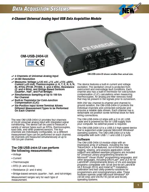
OM-USB-2404-UIU 4 Channels of Universal Analog InputU 24-Bit ResolutionU M easures: Voltage (±125 mV, ±1V, ±4V, ±15V, ±60V), Current (±25 mA), Thermocouples (J, K, T, E, R, S, N,B), RTDs (Pt100, Pt1000, 3- and 4-Wire), Resistance(2- and 4-Wire), and Bridge-Based Sensors(Quarter-, Half-, and Full-Bridge)U S imultaneous Sampling at Up to 100 S/sPer ChannelU B uilt-In Thermistor for Cold-JunctionCompensation (CJC)U S ix-Position Input Screw Terminal Allows Different Measurement Types to be PerformedOn Each ChannelThe new OM-USB-2404-UI provides four channelsof 24-bit universal analog input with integrated signal conditioning. The device can be used to measure a variety of sensor types such as RTDs, thermocouples, load cells, and other powered sensors. The four channels are individually configurable, so a different measurement type can be performed on each channel. All channels are measured simultaneously at up to100 S/s per channel.The OM-USB-2404-UI can performthe following measurements:• Voltage• Current• Thermocouple• RTD (3- and 4-wire)• Resistance (2- and 4-wire)• Bridge-based sensors (quarter-, half-, and full-bridge) Measurement ranges vary for each type ofOM-USB-2404-UI shown smaller than actual size.The device features a built-in current and voltage excitation. The excitation circuit is protected from overcurrent and overvoltage fault conditions. Each channel also has a built-in thermistor for cold-junction compensation (CJC) calculations when measuring thermocouples. An analog pre-filter removes noise that may be present in the signals prior to conversion. With 250 Vac channel-to-channel and channel-to-ground isolation, the OM-USB-2404-UI protects the individual channels and connected computer and ensures a reliable data stream. Each channel has a detachable six-position screw terminal block for field wiring connections.The OM-USB-2404-UI ships with a 2 m (6') USB cable and is powered by the 5V USB supply fromyour computer. No external power is required.The OM-USB-2404-UI is a USB 2.0 high-speed device that is supported under popular Microsoft Windows®operating systems. The OM-USB-2404-UI is fully compatible with both USB 1.1 and USB 2.0 ports. SoftwareThe OM-USB-2404-UI module ships with an impressive array of software, including the new TracerDAQ®, a full-featured, out-of-the-box data logging, viewing, and analysis application. Driver support and detailed example programs are included for Universal Library programming libraries for Microsoft® Visual Studio® programming languages, and other languages, including DASYLab®, and ULx for NI LabVIEW® (comprehensive library of Vls and example programs compatible with 32-bit and 64-bit LabVIEW v8.5 through 2013) and InstaCal™ installation, calibration and test utility-powerful solutions for programmers and nonprogrammers alike. These modules operate under Microsoft Windows® XP(32-bit only) and VISTA/7/8 (32-bit and 64-bit) operating systems.with Measurements.output signals:T racerDAQ PRO is an enhanced version of T racerDAQ. A comparison of some of the features included inANALOG INPUTNumber of Channels: 4A/D Converter Resolution: 24-bitA/D Converter Type: Delta-Sigma with analog pre-filteringSampling Mode: SimultaneousTEDS Sensor Type Supported: IEEE 1451.4 TEDS Class II (interface)Input Mode: Voltage, current, resistance (2- and 4-wire), RTD (3- and 4-wire), thermocouple, quarter-bridge, half-bridge, full-bridgeConversion Time (No channels in TC mode) High Speed: 10 ms for all channelsBest 60 Hz Rejection: 110 ms for all channels Best 50 Hz Rejection: 130 ms for all channels High Resolution: 500 ms for all channelsConversion Time (One or More Channels in TC Mode) High Speed: 20 ms for all channelsBest 60 Hz Rejection: 120 ms for all channels Best 50 Hz Rejection: 140 ms for all channels High Resolution: 510 ms for all channels Overvoltage Protection Terminals 1 and 2: ±30V T erminals 3 Through 6, Across any Combination: ±60VInput ImpedanceVoltage Mode (±60V, ±15V, ±4V): 1 M Ω Current Mode: <40 Ω All Other Modes: >1G ΩInput Bias Current: <1nAIntegral Non-Linearity (INL): ±15 ppmCommon Mode Rejection Ratio (CMRR): >100 dB Normal Mode Rejection Ratio (NMRR) Best 60 Hz Rejection: 90 dB at 60 Hz Best 50 Hz Rejection: 80 dB at 50 HzHigh Resolution:65 dB at 50 Hz and 60 HzCurrent±25 mA ±25 mA4-Wire and 3-Wire RTD, Pt100±15±60Conversion TimeINPUT NOISE (ppm of Range )Resistance, RTD,STABILITYGENERALOperating Temperature Range: 0 to 60ºC (32 to 140ºF), 10 to 90% RH non-condensing Storage Temperature Range: -40 to 85ºC (-40 to 185ºF), 5 to 95% RH non-condensingCommunications: USB 2.0 Hi-Speed mode (480 Mbps) is recommended; otherwise USB 1.1 full-speed mode (12 Mbps)Current Consumption from USB: 500 mA, maximum Channel-to-Earth Ground IsolationC ontinuous: 250 Vrms (measurement category II for measurements performed on circuits directly connected to the electrical distribution system) W ithstand: 2300 Vrms (verified by a 5 second dielectric withstand test)Channel-to-Channel IsolationC ontinuous: 250 Vrms (measurement category II for measurements performed on circuits directly connected to the electrical distribution system) W ithstand: 1390 Vrms (verified by a 5 second dielectric withstand test)Signal I/O Connector: 6-position screw terminalsScrew terminal Wiring: 18 to 28 AWG copper conductor wire with 7 mm (0.28") of insulation stripped from the end Maximum Altitude: 2000 m (6562')Dimensions: 134 L x 143 W x 39 mm H (5.27 x 5.64 x 1.54")Weight: 567 g (1.25 lb)Ordering Example: OM-USB-2404-UI 4-channel universal analog input USB data acquisition module and OCW-1, OMEGACARE SM extendsstandard 1-year warranty to a total of 2 years.TracerDAQ software (included).OM-USB-2404-UI shownsmaller than actual size.OMEGACARE SM extended warranty program is available for models shown on this page. Ask your sales representative for full details whenplacing an order. OMEGACARE SMcovers parts,labor and equivalent loaners.。
M-3004-用户手册-基于Modbus的8AI4DI4DO采集模块V1.1
M-3004用户手册V1.1基于Modbus的8AI/4DI/4DO采集模块1 产品简介M-3004(基于Modbus的8AI/4DI/4DO采集模块)作为通用型模拟量和数字量采集模块广泛应用于冶金、化工、机械、消防、建筑、电力、交通等工业行业中,可接入8路温度、湿度、液位、压力、流量、PH值等传感器输出的0~20mA 或4~20mA模拟量信号,同时具有4路数字量输入通道和4路继电器输出通道。
支持标准的Modbus RTU 协议,并具有通讯超时检测功能,可同其它遵循Modbus RTU 协议的设备联合使用。
1.1 系统概述M-3004模块主要由电源电路、模拟量输入采样电路、数字量输入电路、继电器输出电路、RS485收发电路及MCU等部分组成。
采用高速ARM处理器作为控制单元,拥有隔离的RS485通讯接口,具有ESD、过压、过流保护功能,避免了工业现场信号对模块通讯接口的影响,使通讯稳定可靠。
1.2 主要技术指标1)系统参数供电电压:5~40VDC,电源反接保护功率消耗:最大2.0W(24V供电)工作温度:-10℃~60℃存储温度:-40℃~85℃相对湿度:5%~95%不结露2)模拟量输入参数输入路数:8路单端输入正常输入范围:0~20mA,4~20mA最大输入范围:0~21mA隔离电压:2500VDC输入电阻:120ΩADC分辨率:12位采样精度:0.5%采样速率:10次/s3)数字量输入参数输入路数:4路输入类型:开关触点信号或电平信号隔离电压:2500VDC输入范围:高电平(数字1):5VDC~30VDC,6mA@24V,低电平(数字0):≤1VDC4)继电器输出参数输出路数:4路输出类型:继电器常开输出触点容量:5A 30VDC,5A 250VAC机械寿命:2*107次隔离电压:4000VDC5)通讯接口通讯接口:RS485 接口,隔离1500VDC,±15kV ESD 保护、过流保护隔离电压:1500V通讯协议:Modbus RTU 协议波特率:1.2k,2.4k,4.8k,9.6k,19.2k,38.4k,57.6k,115.2k通讯数据格式:1个起始位,8个数据位,无、奇或偶校验,1个或2个停止位1.3 外形及尺寸外壳材料:ABS工程塑料尺寸大小:145mm(长) * 90mm(宽) * 40mm(高)安装方式:标准DIN35导轨安装和螺钉安装,安装尺寸如图所示。
数采仪说明书
物联网数据采集控制仪使用说明书Operat ing In structi ons物联网数据采集控制仪使用说明书Operating Instructions仪器的商标 (4) 状态显示灯可以显示仪器工作状态,从左至右依次是: GPRS 、充电、保护、过冲、浮充、放电、断电。
(5) 电源开关(POWER )备用电池开关,当按钮被按下时,启用备用电池;当按钮弹起时,切断备用 电池。
后面板说明物联网数据采集控制仪背面板如图1-2所示图1-2 背面板(1)电源接口及开关仪器电源线接口以及开关,插上电源线,当开关处于位置“电源;当开关处于位置“ O ”,断开仪器电源。
(2)SIM 卡插槽可插3G SIM 卡,用于GPRS 模块进行无线数据传输(3)串口扩展外围接口尸尸尸尸尸 目I ”,接通仪器仪器串口扩展模块的外围接口,可扩展4路串口4) I/O 模块外围接口仪器的I/O 扩展模块外围接口,可用于采集8 路模拟量与12 路数字量。
5)扩展板外部接口未使用,可插( 3 )或( 4)模块,用于扩展串口或I/O 。
6)扩展板外部接口未使用,可插( 3 )或( 4)模块,用于扩展串口或I/O 。
7)开关选择从NOR 启动或者NAND 启动,当开关拨到左端,选择从NAND 启动,当开关拨到右端,选择从NOR 启动。
8)RS485 接口用于485 通讯。
9) CAN 接口CAN 总线通讯接口,可进行数据传输。
10)音频接口左侧绿色接口可插耳机,右侧粉色接口可插麦克风。
11)MICRO USB 接口用于给仪器烧写程序。
12)SD 卡槽可插SD 卡,用于扩展存储。
13) USB 接口双USB 接口。
14) RJ45 网口及USB 接口上端是RJ45 网口,可以连接网线,用于与主机通讯;下端是双USB 接口。
15) 串行及视频接口上端为串行通讯接口,下端为VGA 视频接口。
装箱清单1 台主机箱1 条电源线1 本说明书1 条串口线1 个合格证1 包螺丝1 个名牌1 本故障手册安装说明安装环境:温度5 C〜40 C之间;相对湿度在90%以下;大气压力在电源86〜106kPa 。
5069 Compact I O 数字量 4 点隔离型继电器输出模块用户手册说明书
安装说明5069 Compact I/O 数字量 4 点隔离型继电器输出模块产品目录号 5069-OW4I主题页码关于模块5准备事宜5所需组件5安装概要7安装可拆卸端子块8安装模块8安装端盖10对可拆卸端子块进行接线10断开电线与可拆卸端子块之间的连接11接线图11为 5069 Compact I/O 系统供电12拆卸模块12更换模块12模块技术参数13其他资源14产品概述5069-OW4I 数字量 4 点隔离型继电器输出模块用于驱动输出设备。
从控制器和某些输入模块发送至上述模块的数据用于确定 5069-OW4I 模块行为。
5069 Compact I/O™ 模块采用生产者-消费者通信模式。
生产者-消费者通信模式是模块与其他系统设备之间的一种智能数据交换,在通信过程中,每个模块都会生成数据,而不是先被轮询。
5069 Compact I/O 系统与一些 Logix5000™ 控制器配合使用,并通过 Studio 5000 Logix Designer® 应用程序进行配置。
有关 Logix5000 控制器和 Logix Designer 应用程序版本与 5069 Compact I/O 模块兼容的更多信息,请参见第14 页上的其他资源中列出的出版物。
5069 Compact I/O 数字量 4点隔离型继电器输出模块Read this document and the documents listed in the Additional Resources section about installation, configuration and operation of this equipment before you install, configure, operate or maintain this product.注意:在安装、配置、操作和维护本产品前,请阅读本文档以及“其他资源”部分列出的有关设备安装、配置和操作的相应文档。
Omega PT-104 四通道高分辨率温度数据采集模块说明书
The PT-104 is a four-channel, high-resolution temperature data acquisition module for use with Pt100 and Pt1000 RTD sensors. It can also be used to measure resistance (375 Ωand 10,000 Ωranges) and voltage(115 mV or 2.5 V ranges).In Pt100/Pt1000/resistance mode,the unit uses a four-wire circuit. In voltage mode, the input connector can be treated as a differential input with ground, or two single-ended inputs. Both inputs must be 0 V or above, though it does not matter which input has the higher voltage.For the 115 mV voltage range, the accuracy may vary by 2%, and the temperature co-efficient will be 100 ppm/°C.Although accurate temperature sensors are widely available, it has been difficult to take advantage of them due to errors caused by the measuring device.The PT-104, however, is designed to be inherently accurate. Rather than relying on voltage references (which tend to be temperature sensitive) it uses ‘reference’resistors which are extremely stable (low temperature co-efficient and drift).The exact value of each resistor is stored in an EEPROM to provide the ultimate in accuracy (yearly re-calibration is recommended). To achieve the 0.001°C resolution a highly-advanced ADC is used that can resolve to better than 1 part in 16 million.TemperatureThe PT-104 measures temperature using platinum resistancetemperature sensors (RTDs). Both common industry standards (Pt100and Pt1000) are supported. The unit is compatible with 2, 3 and 4 wiresensors (4 wire Pt100 sensors are recommended for accurate measurements).ResistanceWhen measuring resistance, the unit uses a four-wire circuit to give the greatest possible accuracy. Two resistance ranges are available (0 to 375 Ωand 0 to 10,000 Ω). The unit is calibrated for 0 to 375 Ωso this range should be used for VoltageFor voltage measurements, each input connector can be treated as a differential input with ground, or two single-ended inputs. Both inputs must be zero volts or above, though it does not matter which input has the higher voltage. Two voltage ranges are available (0 to 115 mV and 0 to 2500 mV). For the most accurate measurements use the 0 to 2500 mV range.Remote Data CollectionThe PT-104 is normally connected directly to a PC, but it is alsopossible to communicate with the PT-104 using a modem (radio or telephone) so that you can collect data from a remote site.SoftwareThe PT-104 is supplied with Windows ®Logging and Player Software. The software willautomatically detect which sensor is connected and will display readings in the correct units. Also supplied is4-Channel RTD Input Data Acquisition ModulePT-104$660PT-104, $660,shown smaller than actual size.cable, RS-232 to USB converter, and Windows ®ߜMeasures Temperature (RTDs), Resistance and VoltageߜHigh Accuracy (0.01°C) and Resolution (0.001°C)ߜNo Power Supply Required ߜRS-232 or USB Interface (USB Interface via Included RS-232 to USB Interface Converter)ߜFor Use with Pt100 and Pt1000RTD Sensors OMEGACARE SM extended warranty program isavailable for models shown on this page. Ask yoursales representative for full details when placing an order. OMEGACARE SM covers parts, labor and equivalent loaners.2For 4-wire temperature and resistance measurementThe SDK contains a range ofsoftware drivers and example code that you can use to write your own software or to use your PT-104 data logger with third party software.With the included Logging Software you can set the sampling interval from 1 second to several hours and set the maximum number of readings.You can also tell PT-104 dataacquisition module what do to when the temperature readings have been taken - either: stop; repeatimmediately (start again); scroll (oldest recordings disappear); or repeat after delay (where the delay is set by the user).Multiple PT-104 modules can be used simultaneously with the Logging Software. Also, PT-104modules can be mixed with TC-08thermocouple input modules and used at the same time. Up to 20units of any kind (PT-104 or TC-08)can be connected.Using the PT-104 LoggingSoftware, data can be viewed in a spreadsheet and/or in a graph as it is being recorded. Data collected from previous recordings can also be viewed using the Player.PT-104 logging software, displays data in graphical or tabular format.and operator’s manual on CD.Ordering Example: PT-104,4-channel RTD input data acquisition module and OMEGACARE SM 1 year extended warranty for PT-104 ($80)(adds 1 year to standard 2 year warranty), $660 + 66 = $726.ߜProbe Transition Includes Strain Relief Spring at the Cable Exit ߜ Available in Standard and Metric Sizesߜ Temperature Range -200 to 600ºC (Transition and Cable to 260ºC Max)ߜ High-Accuracy, Wire Wound 100 Ω, Class “A” DIN Platinum Elements perIEC 751 (alpha = 0.00385 Ω/Ω/ºC)ߜ 2-, 3-, and 4-Wire Constructions AvailableߜThermal Response (63%) Less Than 75 Milliseconds in Water Flowingat 3 Feet per SecondߜHigh-Accuracy Class “A”, 100 Ω DIN Platinum Elements Standard ߜUltra Precise Accuracy 1⁄3and 1⁄10DIN, and EconomicalClass “B” Also AvailableߜOperating Range Up to 480°C (900°F) Availableߜ1 m (40") Long 2-, 3-, or 4-Wire #26 AWG Cables for Connecting toMost Handheld Instruments ߜ100 Ω DIN Class A (±0.06 Ω or ±0.15°C at 0°C) Accuracy Standard ߜEasy-Installation Silicone-Based, Self-Adhesive Backing Rated to260°C (500°F)ߜSensor Can be Re-appliedߜ290°C (554°F) Short-Term Operation When Used as a “Cement-On”(OMEGABOND ®Air Set Cements)ߜStripped 3-Wire or 4-Wire Leads Standard (Connectors Optional)ߜStocked in 1 m (40") Lengths; Also Available in 2 and 3 m (80 and 120")and Custom Length Lead WiresߜOther Resistances/Accuracies Available on RequestRTD-2-F3105-36-T, $45, for more information, visit /rtd-2-f3105SA1-RTD, $50, for more information, visit /sa1-rtdPR-11-2-100-1/8-6-E, $72,for more information, visit /pr-11cable, RS-232 to USB converter, and Windows ®CANADA www.omega.ca Laval(Quebec) 1-800-TC-OMEGA UNITED KINGDOM www. Manchester, England0800-488-488GERMANY www.omega.deDeckenpfronn, Germany************FRANCE www.omega.fr Guyancourt, France088-466-342BENELUX www.omega.nl Amstelveen, NL 0800-099-33-44UNITED STATES 1-800-TC-OMEGA Stamford, CT.CZECH REPUBLIC www.omegaeng.cz Karviná, Czech Republic596-311-899TemperatureCalibrators, Connectors, General Test and MeasurementInstruments, Glass Bulb Thermometers, Handheld Instruments for Temperature Measurement, Ice Point References,Indicating Labels, Crayons, Cements and Lacquers, Infrared Temperature Measurement Instruments, Recorders Relative Humidity Measurement Instruments, RTD Probes, Elements and Assemblies, Temperature & Process Meters, Timers and Counters, Temperature and Process Controllers and Power Switching Devices, Thermistor Elements, Probes andAssemblies,Thermocouples Thermowells and Head and Well Assemblies, Transmitters, WirePressure, Strain and ForceDisplacement Transducers, Dynamic Measurement Force Sensors, Instrumentation for Pressure and Strain Measurements, Load Cells, Pressure Gauges, PressureReference Section, Pressure Switches, Pressure Transducers, Proximity Transducers, Regulators,Strain Gages, Torque Transducers, ValvespH and ConductivityConductivity Instrumentation, Dissolved OxygenInstrumentation, Environmental Instrumentation, pH Electrodes and Instruments, Water and Soil Analysis HeatersBand Heaters, Cartridge Heaters, Circulation Heaters, Comfort Heaters, Controllers, Meters and SwitchingDevices, Flexible Heaters, General Test and Measurement Instruments, Heater Hook-up Wire, Heating Cable Systems, Immersion Heaters, Process Air and Duct, Heaters, Radiant Heaters, Strip Heaters, Tubular HeatersFlow and LevelAir Velocity Indicators, Doppler Flowmeters, LevelMeasurement, Magnetic Flowmeters, Mass Flowmeters,Pitot Tubes, Pumps, Rotameters, Turbine and Paddle Wheel Flowmeters, Ultrasonic Flowmeters, Valves, Variable Area Flowmeters, Vortex Shedding FlowmetersData AcquisitionAuto-Dialers and Alarm Monitoring Systems, Communication Products and Converters, Data Acquisition and Analysis Software, Data LoggersPlug-in Cards, Signal Conditioners, USB, RS232, RS485 and Parallel Port Data Acquisition Systems, Wireless Transmitters and Receivers。