实验十五 帧中继配置
帧中继配置
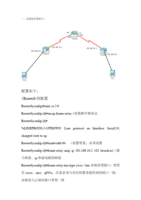
一、实验拓扑图如下:配置如下://Router0的配置Router0(config)#inter se 2/0Router0(config-if)#encap frame-relay //封装帧中继协议Router0(config-if)#%LINEPROTO-5-UPDOWN: Line protocol on Interface Serial2/0, changed state to upRouter0(config-if)#bandwidth 64 //设置带宽,必须设置Router0(config-if)#frame-relay map ip 192.168.10.2 102 broadcast //建立映射,ip和虚电路的映射Router0(config-if)#frame-relay lmi-type cisco //lmi本地管理接口,类型有cisco,ansi,q933a。
注意必须与对应的服务提供商的接口一致,也就是与云端对接口类型一致Router0(config-if)#ip ospf network broadcast //在帧中继上使用ospf 协议的一种方法,开启广播。
Rip不用设置,直接就能使用。
Router0(config-if)#exitRouter0(config)#router ospf 1Router0(config-router)#network 192.168.20.0 0.0.0.255 area 0Router0(config-router)#network 192.168.10.0 0.0.0.255 area 0Router0(config-router)#exit//Router1的配置Router1(config)#interface se 2/0Router1(config-if)#encap frame-relayRouter1(config-if)#%LINEPROTO-5-UPDOWN: Line protocol on Interface Serial2/0, changed state to upRouter1(config-if)#bandwidth 64Router1(config-if)#frame-relay map ip 192.168.10.1 201 broadcast Router1(config-if)#frame-relay lmi-type ansiRouter1(config-if)#%LINEPROTO-5-UPDOWN: Line protocol on Interface Serial2/0, changed state to downRouter1(config-if)#ip ospf p 0 //必须设这权限,让一个路由器成为DRRouter1(config-if)#ip ospf network broadcastRouter1(config-if)#exitRouter1(config)#router ospf 1Router1(config-router)#network 192.168.10.0 0.0.0.255 area 0 Router1(config-router)#network 192.168.40.0 0.0.0.255 area 0 Router1(config-router)#exit//云端的配置选择se0口;DLCI编号:输入102,Name :输入1->2,点击添加Se1类似。
实验十五、帧中继交换机的配置
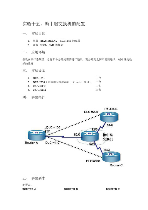
实验十五、帧中继交换机的配置一、实验目的1. 掌握FRAM-RELAY SWITCH 的配置2. 理解DLCI、LMI 等概念二、应用环境假设在银行系统里,总行和各分理处需要进行通讯,而分理处之间不需要通讯,帧中继是最好的选择三、实验设备1. DCR-17512. DCR-2630(安装相应模块满足三个serial 接口)3. CR-V35FC4. CR-V35MT四、实验拓扑五、实验要求配置表:ROUTER-A ROUTER-B 三台一台三条三条ROUTER-CS1/1 192.168.1.1/24 S1/0 192.168.1.2/24 S0/3192.168.1.3/24 PVC DLCI 如图所示六、实验步骤第一步:配置帧中继交换机(配置前请恢复原厂设置)Router#confRouter_config#hostname frswitchfrswitch_config# interface Serial2/0frswitch_config_s2/0# encapsulation frame-relay frswitch_config_s2/0#frame-relay intf-type dce frswitch_config_s2/0# physical-layer speed 64000 frswitch_config# interface Serial2/1frswitch_config_s2/1# encapsulation frame-relay frswitch_config_s2/1#frame-relay intf-type dce frswitch_config_s2/1# physical-layer speed 64000 frswitch_config# interface Serial2/3frswitch_config_s2/3# encapsulation frame-relay frswitch_config_s2/3#frame-relay intf-type dce frswitch_config_s2/3# physical-layer speed 64000 frswitch_config_s2/3#exit !进入接口配置模式!封装帧中继!配置接口类型!配置时钟频率frswitch_config# frswitch Serial2/0 100 Serial2/1 200 !配置PVC转发表frswitch_config#frswitch Serial2/0 110 Serial2/3 300第二步:配置路由器A、B、CRouter-A#confRouter-A_config# interface Serial1/1Router-A_config_s1/1# ip address 192.168.1.1 255.255.255.0 !配置IP地址Router-A_config_s1/1# encapsulation frame-relayRouter-B#confRouter-B_config# interface Serial1/0Router-B_config_s1/0# ip address 192.168.1.2 255.255.255.0Router-B_config_s1/0#encapsulation frame-relay_config#int s0/3Router-C_config_s0/3#Router-C #confRouter-C _config#int s0/3Router-C _config_s0/3#ip address 192.168.1.3 255.255.255.0Router-C _config_s0/3# encapsulation frame-relay第三步:查看各路由器接口状态Router-A#sh int s1/1!封装帧中继Serial1/1 is up, line protocol is upMode=Sync DTEDTR=UP,DSR=UP,RTS=UP,CTS=UP,DCD=UPInterface address is 192.168.1.1/24MTU 1500 bytes, BW 64 kbit, DLY 2000 usec Encapsulation Frame-relay, loopback not setKeepalive set(10 sec)FrameRelay DTE, LMI type AutosenseLMI DTE Link Errors 1, Protocol Errors 0, Inactives 0T391 10, N391 6, N392 3, N393 4Recvd Octets 15177, Recvd Frames 913, Recvd Discards 2Sent Octets 12767, Sent Frames 912, Sent Discards 0Recvd Errors 0, Sent Errors 0, Recvd Unknowns 060 second input rate 15 bits/sec, 0 packets/sec!60 second output rate 12 bits/sec, 0 packets/sec!987 packets input, 18264 bytes, 5 unused_rx, 0 no buffer0 input errors, 0 CRC, 0 frame, 0 overrun, 0 ignored, 0 abort1043 packets output, 17759 bytes, 8 unused_tx, 0 underruns error:0 clock, 0 gracePowerQUICC SCC specific errors:0 recv allocb mblk fail 0 recv no buffer0 transmitter queue full 0 transmitter hwqueue_fullRouter-B#sh int s1/0Serial1/0 is up, line protocol is upMode=Sync DTEDTR=UP,DSR=UP,RTS=UP,CTS=UP,DCD=UPInterface address is 192.168.1.2/24MTU 1500 bytes, BW 64 kbit, DLY 2000 usec Encapsulation Frame-relay, loopback not setKeepalive set(10 sec)FrameRelay DTE, LMI type AutosenseLMI DTE Link Errors 1, Protocol Errors 0, Inactives 0T391 10, N391 6, N392 3, N393 4Recvd Octets 12867, Recvd Frames 834, Recvd Discards 0Sent Octets 11779, Sent Frames 836, Sent Discards 3Recvd Errors 0, Sent Errors 0, Recvd Unknowns 060 second input rate 14 bits/sec, 0 packets/sec!60 second output rate 12 bits/sec, 0 packets/sec!905 packets input, 15828 bytes, 3 unused_rx, 0 no buffer0 input errors, 0 CRC, 0 frame, 0 overrun, 0 ignored, 0 abort1036 packets output, 18275 bytes, 8 unused_tx, 0 underruns error:0 clock, 0 gracePowerQUICC SCC specific errors:0 recv allocb mblk fail 0 recv no buffer0 transmitter queue full 0 transmitter hwqueue_fullRouter-C#sh int s0/3Serial0/3 is up, line protocol is upMode=Sync DTEDTR=UP,DSR=UP,RTS=UP,CTS=UP,DCD=UPInterface address is 192.168.1.3/24MTU 1500 bytes, BW 64 kbit, DLY 2000 usecEncapsulation Frame-relay, loopback not setKeepalive set(10 sec)FrameRelay DTE, LMI type AutosenseLMI DTE Link Errors 1, Protocol Errors 0, Inactives 0T391 10, N391 6, N392 3, N393 4Recvd Octets 472, Recvd Frames 31, Recvd Discards 0Sent Octets 464, Sent Frames 33, Sent Discards 0Recvd Errors 0, Sent Errors 0, Recvd Unknowns 060 second input rate 14 bits/sec, 0 packets/sec!60 second output rate 12 bits/sec, 0 packets/sec!31 packets input, 534 bytes, 7 unused_rx, 0 no buffer0 input errors, 0 CRC, 0 frame, 0 overrun, 0 ignored, 0 abort41 packets output, 722 bytes, 8 unused_tx, 0 underrunserror:0 clock, 0 gracePowerQUICC SCC specific errors:0 recv allocb mblk fail 0 recv no buffer0 transmitter queue full 0 transmitter hwqueue_full第四步:查看帧中继状态Router-A#sh frame-relayFrame Relay/IP stateSerial1/1 UP====================================================================== Port DLCI State remote IP local IPType======================================================================Serial1/1 100ACTIVE192.168.1.2 192.168.1.1 ISerial1/1 110 ACTIVE192.168.1.3 192.168.1.1 IRouter-B#sh frame-relayFrame Relay/IP stateSerial1/0 UP======================================================================Port DLCI State remote IP local IP Type====================================================================== Serial1/0 200 ACTIVE192.168.1.1 192.168.1.2IRouter-C#sh frame-relayFrame Relay/IP stateSerial0/3 UP======================================================================Port DLCI State remote IP local IP Type======================================================================Serial0/3 300ACTIVE192.168.1.1 192.168.1.3 I七、注意事项和排错1. 帧中继交换机不要配置IP 地址2. 配置PVC 的DLCI 一定要对应3. 路由器接口只需要封装帧中继八、配置序列frswitch#sh run正在收集配置...当前配置:!!version 1.3.1Sservice timestamps log dateservice timestamps debug dateno service password-encryption!hostname frswitch!!!!!!interface FastEthernet0/0no ip addressno ip directed-broadcast!interface Ethernet1/0no ip addressno ip directed-broadcastduplex halfinterface Serial2/0no ip addressno ip directed-broadcast encapsulation frame-relayframe-relay intf-type dce physical-layer speed 64000!interface Serial2/1no ip addressno ip directed-broadcast encapsulation frame-relayframe-relay intf-type dcephysical-layer speed 64000!interface Serial2/2no ip addressno ip directed-broadcast!interface Serial2/3no ip addressno ip directed-broadcast encapsulation frame-relayframe-relay intf-type dcephysical-layer speed 64000!interface Async0/0no ip addressno ip directed-broadcast!!!!!!!!gateway-cfgGateway keepAlive 60 shutdown!frswitch Serial2/0 100 Serial2/1 200 frswitch Serial2/0 110 Serial2/3 300 !!!!ivr-cfg!!!九、共同思考1. 路由器的DLCI 有什么意义?是如何得到的?2. 为什么帧中继交换机不配置IP 地址?3. 帧中继的MAP 是如何得到的?十、课后练习请重复以上实验十一、相关命令详解frswitch这个全局配置命令在帧中继的DCE 或NNI 上激活PVC 交换。
15 建立帧中继连接

© 2004,Enhan info, Inc. All rights reserved.建立帧中继的连接目标通过本章学习,你能够完成以下内容:•给定一个路由器,使用Cisco IOS命令去配制一个可操作的串型帧中继连接和帧中继的子接口.•使用show命令去检验帧中继的连接配置.•使用debug命令去检验帧中继的连接配置.帧中继概述© 2002, Cisco Systems, Inc. All rights reserved.4目标通过本章学习,你能够完成以下内容:•描述帧中继网络的特性和操作•定义一些重要的帧中继网络中的概念如local access rate, virtualcircuit, PVC, SVC, DLCI, CIR, circuit, PVC, SVC, DLCI, CIR, InARP InARP InARP, LMI, FECN,, LMI, FECN, 和BECN帧中继概述是由国际电信联盟通信标准化组和美国国家标准化协会制定的一种标准。
它定义在公共数据网络上发送数据的过程。
它是一种面向连接的数据链路技术,为提供高性能和高效率数据传输进行了技术简化,它靠高层协议进行差错校正,并充分利用了当今光纤和数字网络技术。
帧中继的作用帧使用DLCI进行标识,它工作在第二层;帧中继的优点在于它的低开销。
帧中继在带宽方面没有限制,它可以提供较高的带宽。
典型速率56K-2M/s内。
本章目标通过本章的学习,您应该掌握以下内容:•了解Frame Relay 工作过程•配置Frame Relay•配置Frame Relay 的子端口•查看Frame Relay 信息学员思考 五个点要求能两两互连,如何连接?每个点需要多少串口?Full MeshPartial MeshStar (Hub and Spoke)全网结构:提供最大限度的相互容错能力;物理连接费用最为昂贵。
部分网格结构:对重要结点采取多链路互连方式,有一定的互备份能力。
帧中继概念 帧中继配置命令有哪些
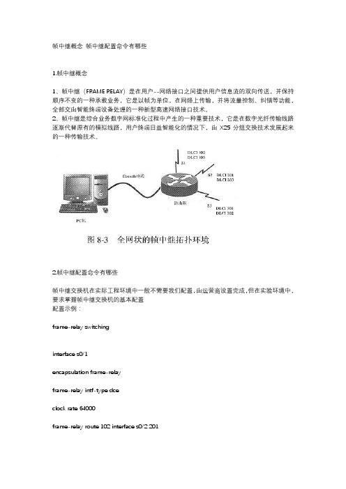
帧中继概念帧中继配置命令有哪些1.帧中继概念1、帧中继(FRAME RELAY)是在用户--网络接口之间提供用户信息流的双向传送,并保持顺序不变的一种承载业务,它是以帧为单位,在网络上传输,并将流量控制、纠错等功能,全部交由智能终端设备处理的一种新型高速网络接口技术。
2、帧中继是综合业务数字网标准化过程中产生的一种重要技术,它是在数字光纤传输线路逐渐代替原有的模拟线路,用户终端日益智能化的情况下,由X25分组交换技术发展起来的一种传输技术。
2.帧中继配置命令有哪些帧中继交换机在实际工程环境中一般不需要我们配置,由运营商设置完成,但在实验环境中,要求掌握帧中继交换机的基本配置配置示例:frame-relay switchinginterface s0/1encapsulation frame-relayframe-relay intf-type dceclock rate 64000frame-relay route 102 interface s0/2 201// 定义PVC,该条命令是,s0/1口的DLCI 102,绑定到s0/2口的201 DLCI号frame-relay route 103 interface s0/3 301no shutdown主接口运行帧中继(Invers-arp)FRswitch(帧中继交换机)的配置:frame-relay switchinginterface s0/1 // 连接到R1的接口encapsulation frame-relayframe-relay intf-type dceclock rate 64000frame-relay route 102 interface s0/2 201// 定义PVC,该条命令是,s0/1口的DLCI 102,绑定到s0/2口的201 DLCI号no shutdowninterface s0/2 // 连接到R2的接口encapsulation frame-relayframe-relay intf-type dceclock rate 64000frame-relay route 201 interface s0/1 102no shutdownR1的配置如下:interface serial 0/0ip address 192.168.12.1 255.255.255.252encapsulation frame-relay// 接口封装FR,通过invers-arp发现DLCI,并建立对端IP到本地DLCI的映射(帧中继映射表)no shutdownR2的配置如下:interface serial 0/0ip address 192.168.12.2 255.255.255.252encapsulation frame-relayno shutdown在FRswitch上查看PVI(验证配置):FRswitch#show frame-relay routeInput Intf Input Dlci Output Intf Output Dlci StatusSerial0/1 102 Serial0/2 201 activeSerial0/2 201 Serial0/1 102 active在R1上查看帧中继映射R1#show frame-relay mapSerial0/0 (up): ip 192.168.12.2 dlci 102(0x66,0x1860), dynamic,broadcast,, status defined, activeR1#ping 192.168.12.2Type escape sequence to abort.Sending 5, 100-byte ICMP Echos to 192.168.12.2, timeout is 2 seconds:环境2 主接口运行帧中继(静态映射)FRswitch的配置同上,这里不再赘述上述案例是终端路由器采用动态invers-arp获取帧中继相关映射信息,本例采用静态建立映射的方式进行配置。
帧中继实验配置
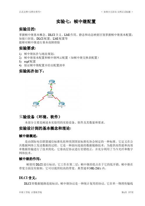
实验七:帧中继配置实验目的:掌握帧中继基本概念、DLCI含义、LMI作用、静态和动态映射区别掌握帧中继基本配置:如接口封装、DLCI配置、LMI配置等能够对帧中继进行基本故障排除实验要求:1)帧中继拓扑与地址规划;2)帧中继基本配置和帧中继网云配置(如帧中继交换表配置)3)ospf配置4)验证帧中继配置并给出配置清单实验拓扑如下:实验设备(环境、软件)本部分主要是阐述本实验用的实验设备、软件及其数量和要求。
实验设计到的基本概念和理论:帧中继概述:是由国际电信联盟通信标准化组和美国国家标准化协会制定的一种标准。
它定义在公共数据网络上发送数据的过程。
它是一种面向连接的数据链路技术,为提供高性能和高效率数据传输进行了技术简化,它靠高层协议进行差错校正,并充分利用了当今光纤和数字网络技术。
帧中继的作用:帧使用DLCI进行标识,它工作在第二层;帧中继的优点在于它的低开销。
帧中继在带宽方面没有限制,它可以提供较高的带宽。
典型速率56K-2M/s内。
DLCI含义:DLCI即数据链路连接标识,帧中继协议是一种统计复用的协议,它在单一物理传输线路上能够提供多条虚电路。
每条虚电路都是用DLCI(Data Link Connection Identifier)来标识。
虚电路是面向连接的,它将用户数据帧按顺序传送至目的地。
从建立虚电路的方式的不同,将帧中继虚电路分为两种类型:永久虚电路(PVC)和交换虚电路(SVC)。
永久虚电路是指给用户提供固定的虚电路。
这种虚电路是通过人工设定产生的,如果没有人为取消它,它是一直存在的。
交换虚电路是指通过协议自动分配的虚电路,当本地设备需要与远端设备建立连接时,它首先向帧中继交换机发出“建立虚电路请求”报文,帧中继交换机如果接受该请求,就为他分配一虚电路。
在通信结束后,该虚电路可以被本地设备或交换机取消。
这种虚电路的创建/删除不需要人工操作。
LMI的作用:LMI即本地管理接口,它是一种存活机制,他提供路由器和帧中继交换机之间的帧中继连接的状态信息。
帧中继配置(点到点)
帧中继是ISP提供的一种广域网服务,是一种网络与数据终端设备(DTE)接口标准,多用于公司总部与分支机构互连。
帧中继的主要特点是:使用光纤作为传输介质,因此误码率极低,能实现近似无差错传输,减少了进行差错校验的开销,提高了网络的吞吐量;帧中继是一种宽带分组交换,使用复用技术时,其传输速率可高达44.6Mbps。
但是,帧中继不适合于传输诸如话音、电视等实时信息,它仅限于传输数据。
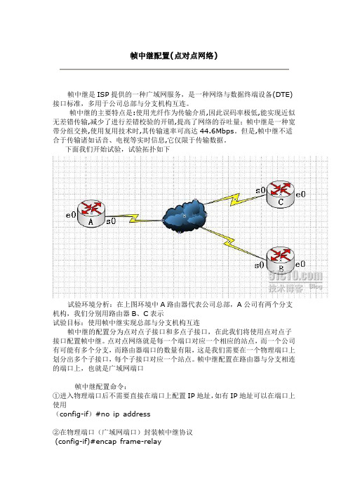
下面我们开始试验,试验拓扑如下试验环境分析:在上图环境中A路由器代表公司总部,A公司有两个分支机构,我们分别用路由器B、C表示试验目标:使用帧中继实现总部与分支机构互连帧中继的配置分为点对点子接口和多点子接口,在此我们将使用点对点子接口配置帧中继。
点对点网络就是每一个端口对应一个相应的站点,而一个公司有可能有多个分支,而路由器端口的数量有限,这是我们需要在一个物理端口上划分出多个子接口,每个子接口对应一个站点。
帧中继配置在路由器与分支相连的端口上,也就是广域网端口帧中继配置命令:①进入物理端口后不需要直接在端口上配置IP地址,如有IP地址可以在端口上使用(config-if)#no ip address②在物理端口(广域网端口)封装帧中继协议(config-if)#encap frame-relay③激活物理端口(config-if)#no shutdown④在物理端口上建立子接口,并指定接口类型(config-if)#interface 子接口point-to-point⑤给子接口配置IP地址和子网掩码(config-subif)#ip address IP地址子网掩码⑥给子接口配置DLCI值(config-subif)#frame-relay interface-dlci DLCI值⑦给子接口配置端口速率(config-sibif)#bandwidth 带宽DLCI值IP地址规划A:e0---192.168.10.1 B:e0---192.168.20.1 C:e0---192.168.30.1 s0.1--202.110.100.1 s0---202.110.100.2 s0---202.110.10 1.2s0.2--202.110.101.1一、配置A路由器A(config)#interface e0 进入局域网端口A(config-if)#ip address 192.168.10.1 255.255.255.0配置局域网I P和掩码A(config-if)#no shutdown激活局域网端口A(config-if)# interface s0 进入广域网端口A(config-if)#no ip address 删除广域网端口的IPA(config-if)#no shutdown 激活广域网A(config-if)#encap frame-relay封装帧中继协议A(config-if)#interface s0.1 point-to-point 在物理端口上建立子接口S0.1,指定端口类型A(config-subif)#ip address 202.110.100.1 255.255.255.0给子接口配置IP和掩码A(config-subif)#frame-relay interface-dlci 102 给S0.1子接口封装DLCIA(config-subif)#bandwidth 64给S0.1子接口配置A(config-subif)#interface s0.2 point-to-point 建立子接口S0.2,并指定子接口类型A(config-subif)#ip address 202.110.101.1 255.255.255.0 给子接口S0.2配置IP和掩码A(config-subif)#frame-relay interface-dlci 103给S0.2子接口封装DLCIA(config-subif)#bandwidth 64 给S0.2子接口配置端口速率A(config-subif)#exit 退出子接口A(config)#router eigrp 100 配置路由,协议为EIGRPA(config-router)#net 192.168.10.0A(config-router)#net 202.110.100.0A(config-router)#net 202.110.101.0二、配置B路由器B路由器上有两个端口,一个是局域网端口E0,一个是广域网端口S0,S0为连接A路由器的S0.1端口,不需要配置子接口,只需要配置IP地址然后封装帧中继协议即可B(config)#int e0B(config-if)#ip address 192.168.20.1 255.255.255.0B(config-if)#no shutdownB(config-if)#int s0B(config-if)#ip address 202.110.100.2 255.255.255.0B(config-if)#encap frame-relayB(config-if)#frame-relay interface-dlci 201B(config-if)#bandwidth 64B(config-if)#no shutB(config-if)#exitB(config)#router eigrp 100B(config-router)#net 192.168.20.0B(config-router)#net 202.110.100.0三、配置路由器CC路由器有两个端口,E0为局域网端口。
帧中继的配置

帧中继的配置一.帧中继帧中继协议是一个第二层协议,即数据链路层协议,它工作在OSI参考模型的物理层和数据链路层。
帧中继提供面向连接的数据链路层通讯,由于其可靠的性能,因此目前成为一种非常重要的广域网技术。
在学习帧中继的过程中,以下的几个术语及与其相关的技术是必须要重点掌握的内容:●虚电路(Virtual circuit):为保证两个DTE设备(如路由器)之间的双向通信而创建的逻辑链路称为虚电路(VC),帧中继用虚电路来提供端点之间的连接,用DLCI来标识;●永久虚电路(Permanent VC-PVC):由服务提供商预先设置,在需要经常通过帧中继网络进行数据传送的DTE设备之间建立的永久逻辑连接,称为永久虚电路(PVC);●交换虚电路(Switched VC-SVC):在只需要通过帧中继网络进行零星数据传送的DTE 设备之间建立的临时的逻辑连接,称为交换虚电路(SVC),它是动态设置的虚电路;●DLCI:数据链路连接标识符(Data-Link Connection Identifier),是帧中继帧头的地址字段中用来区分VC的10bits标识,该标识具有本地意义,只涉及到本地路由器和所连帧中继交换机之间的那一部分,只是路由器和帧中继交换机之间表示VC的数字,因此,远端设备可以用与本地设备相同或完全不同的DLCI表示同样一条逻辑连接,两端的DLCI互不相干。
帧中继交换机通过在一对路由器之间映射DLCI来创建虚电路;●本地访问速率(Local Access Rate):指连接到帧中继云团的连接(本地回路)的时钟速度(端口速度),是数据流入或流出网络的速率;●LMI:本地管理接口(Local Management Interface),是用户设备(DTE)和帧中继交换机(DCE)之间的信令标准,它负责管理设备之间的连接并维护设备之间的连接状态;●CIR:承诺信息速率(Committed Information Rate):申请帧中继服务时服务提供商(ISP)承诺提供的有保证的速率,CIR是在正常条件下帧中继网络保证为用户传送数据所提供的最大平均数据速率;●Inverse ARP:反向地址解析协议(Inverse Address Resolution Protocol),动态地把远端设备的网络层地址与本地DLCI相关联的方法,使本地路由器能自动发现与一个VC相关联的远端设备的网络层地址;●帧中继映射:作为第二层的协议,帧中继协议必须有一个与第三层协议之间建立关联的手段,才能用它来实现网络层的通信,帧中继映射即实现这样的功能,它把网络层地址和DLCI之间进行映射。
帧中继(ppp)实验

拓扑图:配置过程:1、添加3台路由器,我用的是2811,为路由器添加S端口模块,我用的是NM-4A/S模块。
2、添加一个Cloud-PT-Empty设备(Cloud0)模拟帧中继网络,为Cloud0添加3个S端口模块,好与路由器连接!3、设置好S1,S2,S3,的DLCI值:4、配置好Frame-relay连接:5、连接端口注意:路由器作为DTE设备,Cloud0作为DCE设备,按照拓扑添加3台PC 作测试用,连接到路由器F端口,并启动各连接端口。
为各PC设置好IP和网关:PC1: IP:192.168.10.10/224 网关:192.168.10,1PC2: IP:192.168.20.20/224 网关:192.168.20,1PC3: IP:192.168.30.30/224 网关:192.168.30,1二、配置3台路由器:R1路由器配置:Router>enRouter#conf tRouter(config)#int f0/0 进入S1/0端口配置Router(config-if)#ip address 192.168.10.1 255.255.255.0Router(config-if)#no shutdownRouter(config-if)#exitRouter(config)#int serial 1/0Router(config-if)#clock rate 64000Router(config-if)#no shutdown 启动端口Router(config-if)#encapsulation frame-relay 帧中继封装Router(config-if)#frame-relay lmi-type cisco 帧中继类型为ciscoRouter(config-if)#exitRouter(config)#int s1/0.1 point-to-point 配置子端口,并设置为点对点模式Router(config-subif)#ip address 192.168.1.1 255.255.255.0 分配子端口ip地址Router(config-subif)#frame-relay interface-dlci 102 指定点对点对应的DLCI值Router(config-subif)#exitRouter(config)#interface s1/0.2 point-to-point 配置子端口,并设置为点对点模式Router(config-subif)#ip address 192.168.2.1 255.255.255.0 分配子端口ip地址Router(config-subif)#frame-relay interface-dlci 103 指定点对点对应的DLCI值Router(config-subif)#no shutdownRouter(config-subif)#exitrouter ripnetwork 192.168.1.0network 192.168.2.0network 192.168.10.0R2路由器配置:Router>enRouter#conf tRouter(config)#int f0/0Router(config-if)#ip address 192.168.20.1 255.255.255.0Router(config-if)#exitRouter(config)#int s1/0Router(config-if)#clock rate 64000Router(config-if)#no shutdownRouter(config-if)#encapsulation frame-relayRouter(config-if)#frame-relay lmi-type ciscoRouter(config-if)#exitRouter(config)#int s1/0.1 point-to-pointRouter(config-subif)#ip address 192.168.1.2 255.255.255.0 Router(config-subif)#frame-relay interface-dlci 201 Router(config-subif)#no shutdownRouter(config-subif)#exitRouter(config)#int s1/0.2 point-to-pointRouter(config-subif)#ip address 192.168.3.1 255.255.255.0 Router(config-subif)#frame-relay interface-dlci 203 Router(config-subif)#no shutdownRouter(config-subif)#exitRouter(config)#router ripRouter(config-router)#network 192.168.20.0Router(config-router)#network 192.168.1.0Router(config-router)#network 192.168.3.0R3路由器配置:Router>enRouter#conf tRouter(config)#int f0/0Router(config-if)#ip address 192.168.30.1 255.255.255.0 Router(config-if)#no shutdownRouter(config-if)#exitRouter(config)#int s1/0Router(config-if)#clock rate 64000Router(config-if)#no shutdownRouter(config-if)#encapsulation frame-relayRouter(config-if)#frame-relay lmi-type ciscoRouter(config-if)#exitRouter(config)#int s1/0.1 point-to-pointRouter(config-subif)#ip address 192.168.3.2 255.255.255.0 Router(config-subif)#frame-relay interface-dlci 302 Router(config-subif)#no shutdownRouter(config-subif)#exitRouter(config)#int s1/0.2 point-to-pointRouter(config-subif)#ip address 192.168.2.2 255.255.255.0 Router(config-subif)#frame-relay interface-dlci 301 Router(config-subif)#no shutdownRouter(config-subif)#exitRouter(config)#router ripRouter(config-router)#network 192.168.30.0Router(config-router)#network 192.168.3.0Router(config-router)#network 192.168.2.0。
- 1、下载文档前请自行甄别文档内容的完整性,平台不提供额外的编辑、内容补充、找答案等附加服务。
- 2、"仅部分预览"的文档,不可在线预览部分如存在完整性等问题,可反馈申请退款(可完整预览的文档不适用该条件!)。
- 3、如文档侵犯您的权益,请联系客服反馈,我们会尽快为您处理(人工客服工作时间:9:00-18:30)。
《网络工程与实践》实验报告
实验名称帧中继配置实验室502实验日期2015.6.2
【实验目标】
通过本案例,你可以掌握如下技能:
1)理解帧中继交换表的工作原理
2)理解PVC的概念
3)帧中继的基本配置
4)帧中继的动态映射
5)帧中继的静态映射
【技术原理】
帧中继用途:是一种用于连接计算机系统的面向分组的通信方法。它主要用在公共或专用网上的局域网互联以及广域网连接。大多数公共电信局都提供帧中继服务,把它作为建立高性能的虚拟广域连接的一种途径。帧中继是进入带宽范围从56Kbps到1.544Mbps的广域分组交换网的用户接口。帧中继概念;一种用于统计复用分组交换数据通信的接口协议,分组长度可变,传输速度为2.408Mb/s或更高,没有流量控制也没有纠错。DLCI含义:帧中继地址映射用到的数据链路控制标识符。LMI作用:本地管理状态用于管理DT设备与DCE设备之间的连接状态。
注意:Hub的2个子接口共有3条虚电路101、102和103,输出表明这3条pvc均已正常激活。
验证pvc映射、Hub#sh frame-relay map
注意,上述输出表明,Hub的3条pvc实现了正常的pvc映射,其中点对点子接口无需动态或静态映射,多点子接口可动态或静态映射,在本例中实现的是动态映射。在某些情况下,若动态映射失败,可手工静态配置,例如,要配置Hub的DLCI 102与R2(172.16.1.10)之间的静态映射,可使用命令frame-relay map ip 172.16.1.10 102 broadcast。
2)在R1上
3)在R2上
7、配置RIPv2实现全网连通性
1)在Hub上
Hub(config)#router rip
Hub(config-router)#version 2
Hub(config-router)#no auto-summary
Hub(config-router)#network 172.16.0.0
注意:此子接口的DLCI为101,在帧中继网云中是连接R1的虚电路标识。
3)配置多点子接口
注意:此子接口有2个DLCI:102和103,在帧中继网云中是连接R2和R2的虚电路标识。
5.2、配置R1路由器
1)在S0/0接口上配置帧中继封装和LMI类型
注意:在帧中继云的配置中,Serial1接口连接R1的s0/0接口,且LMI类型是q933a。
【实验结果】
8、验证全网连通性
1)在Hub上
Hub#sh ip ro
……
172.16.0.0/16 is variably subnetted, 2 subnets, 2 masks
C 172.16.1.0/30 is directly connected, Serial0/0/0.100
C 172.16.1.8/29 is directly connected, Serial0/0/0.900
R1#conf t
R1(config)#int s0/0
R1(config-if)# encapsulation frame-relay
R1(config-if)# frame-relay lmi-type q933a
No shutdown
2)配置点对点子接口
注意:路由器的串行接口缺省为多点接口,而Hub与R1连接的子接口类型是点对点,故R1对于的接口也应配置为点对点,其DLCI为100,在帧中继网云中是连接Hub的虚电路标识。
3)在R2上
R2#conf t
R2(config)#router rip
R2(config-router)#version 2
R2(config-router)#no auto-summary
R2(config-router)#network 192.168.2.0
R2(config-router)#network 172.16.0.0
5)根据实际需要配置点对点子接口或多点接口。
6)用show frame-reply pvc/map/lmi验证帧中继的配置。
R3#conf t
R3 (config)# interface Serial0/0
R3 (config-if)# ip address 172.16.1.11 255.255.255.248
R3 (config-if)# encapsulation frame-relay
R3 (config-if)# frame-relay interface-dlci 301
2)在R1上
R1#conf t
R1(config)#router rip
R1(config-router)#version 2
R1(config-router)#no auto-summary
R1(config-router)#network 192.168.1.0
R1(config-router)#network 172.16.0.0
Hub#
2)在R1、R2和R3上
从略
//注意:若RIP配置正确,应获得全网的连通性。由于Hub与R2和R3之间是全互联拓扑,不会遇到水平分割问题,如果是中心与周边的星型拓扑,会由于水平分割导致R2和R3的路由表不全。这种情况下Hub与R2和R3之间可使用缺省和静态路由配置。
3)用3台PC互Ping验证连通性
【配置总结】
1)封装帧中继协议,主要类型有cisco和ietf,Cisco路由器缺省为cisco。
2)配置服务商提供的本地DLCI。
3)配置DLCI与IP的映射。对于点对点子接口无需配置,对于多点子接口有动态和静态配置,反向解析协议可动态获得映射表。若动态映射不成功,可静态配置。
4)配置本地管理接口类型,根据帧中继云的配置决定,也可由接口自动配置。
R3 (config-if)# frame-relay interface-dlci 302
No shutdown
6、验证帧中继配置
1)在Hub上:
验证LMI、Hub#sh frame-relay lmi
注意:Hub的2个子接口都连接到帧中继网云的Serial0接口,其LMI类型皆为ansi
验证pvc、Hub#sh frame-relay pvc
4)在R3上
R3#conf t
R3(config)#router rip
R3(config-router)#version 2
R3(config-router)#no auto-summary
R3(config-router)#network 192.168.3.0
R3(config-router)#network 172.16.0.0
R1#conf t
R1 (config)#int Serial0/0.100 point-to-point
R1 (config-subif)# ip address 172.16.1.2 255.255.255.252
R1 (config-subif)# frame-relay interface-dlci 100
4、在帧中继网云的4个串行接口上配置lmi类型及DLCI
4.2、在帧中继网云上配置帧中继交换表如下
5、配置帧中继
5.1、配置hub路由器
1)在S0/0/0接口上配置帧中继封装和LMI类型
注意:在帧中继云的配置中,Serial0接口连接Hub的s0/0/0接口,且LMI类型是ansi
2)配置点对点子接口
R2 (config-if)# encapsulation frame-relay
R2 (config-if)# frame-relay lmi-type ansi
R2 (config-if)# frame-relay interface-dlci 201
R2 (config-if)# frame-relay interface-dlci 203
R 192.168.1.0/24 [120/1] via 172.16.1.2, 00:00:13, Serial0/0/0.100
R 192.168.2.0/24 [120/1] via 172.16.1.10, 00:00:19, Serial0/0/0.900
R 192.168.3.0/24 [120/1] via 172.16.1.11, 00:00:24, Serial0/0/0.900
【实验设备】
1台2811路由器,3台2621XM路由器,3台PC,1个空白网云。
【实验步骤】
1、新建拓扑图
给所有路由器添加1个WIC-2T模块;
给帧中继网云添加4个PT-CLOUD-NM-1S模块,接口编号为Serial0~ Serial03。
2、配置3台PC机的IP
3、修改路由器名称并配置路由器与PC机相连的接口IP地址
No shutபைடு நூலகம்own
5.3、配置R2路由器
注意:Hub与R1连接的子接口是多点类型,而路由器的串行接口缺省为多点接口,故R2无需配置子接口,可直接在物理接口上配置。R3相同,后面不再赘述。
R2#conf t
R2 (config)# interface Serial0/0
R2 (config-if)# ip address 172.16.1.10 255.255.255.248
No shutdown
注意:在帧中继云的配置中,Serial2接口连接R2的s0/0接口,且LMI类型是ansi。此接口有2个DLCI:201和203,在帧中继网云中是连接Hub和R3的虚电路标识。实际上,Hub、R2和R3之间是全互联拓扑。
5.4、配置R3路由器
注意:在帧中继云的配置中,Serial3接口连接R3的s0/0接口,且LMI类型是cisco,路由器封装帧中继后,LMI类型缺省即为cisco,故无需配置。此接口有2个DLCI:301和302,在帧中继网云中是连接Hub和R2的虚电路标识。