连接器界面尺寸汇总
基本连接器识图

3、客戶承認圖中 A.材質及電鍍方式(MATERIAL AND FINISH )
a.塑膠(HOUSING)材質規格、防火等級;
b.端子(CONTACT)材質規格、電鍍規格;
B.機械特性(MECHANICAL CHARACTERISTICS ) a.插入力(Insertion Force ); b.拔出力(Withdrawal Force ); c.保持力(Retention force ); d.耐久性(Durability )
C.電氣特性 a.額定電流(Current rating ); b.接觸電阻(Contact resistance ); c.絕緣電阻(Insulation Resistance ); d.耐電壓(Dielectric Withstanding Resistance ) e.適用溫度(Operating temperature )
引標注加“ ”符號表示(*為數字1.2.3…),然后 在注解處對應該符號作說明即可﹔ d.所使用材質規格.防火等級.及最大次料添加比例 ; e.重點尺寸與CPK標識符號說明及CPK規格﹔ f.模穴號CAV.NO.允許高出或下陷于表面最大值﹔
g.澆口GATE與頂針痕跡允許高出或下陷于所在表面 最大值﹔
(1) 設定:
尺寸標注樣式Dimension style之具體設定如 下列圖一至圖五所示:
圖一 尺寸線和箭頭(Lines and Arrows) 設定欄
圖二 文字(Text) 設定欄
圖三 調整(Fit) 設定欄
圖四 主單位(Primary Units) 設定欄
圖五 公差(Tolerances) 設定欄
標注加“ ”符號表示(*為數字1.2.3…),然后在注 解處對應該符號作說明即可﹔ d.重點尺寸與CPK標識符號說﹔ e.電鍍區域及鍍層規格 ; f.產品包裝方式; g.所使用材質規格.厚度 ; h.允許毛邊.銅絲.拉傷.壓傷等品質異常的最大狀況﹔
冷压接线端子尺寸标准
冷压接线端子尺寸标准
冷压接线端子的尺寸标准主要包括以下两个方面:
1. 圆环冷压端子的直径:通常根据电线直径和所需电流选择合适的圆环直径。
一般的直径规格有4mm、5mm、6mm、8mm、10mm、12mm、
16mm、20mm等。
2. 导线插槽宽度:导线插槽宽度应与导线直径相适应,确保导线插入后能牢固固定在环端子上。
一般而言,导线插槽的宽度与圆环的直径成正比,可根据实际需要进行选择。
常见的有、、、、、等。
请注意,以上为冷压接线端子的部分尺寸标准,建议查阅产品使用说明书或咨询厂家了解完整的尺寸标准。
常用界面尺寸WR28 BJ320波导同轴转换

在广播电视发射系统和微波通讯领域中,同轴矩形波导转换是一个不可缺少的元件,在很多微波系统中,例如:天线、发射机、接收机和载波终端设备等,普遍用到了同轴波导转换。
在微波输入、输出电路中,较强的反射波将可能对发射机或其它级联器件的正常工作造成严重干扰,导致微波系统性能不稳定,因此对转换的基本要求是:(1)低驻波、低插入损耗;(2)有足够的频带宽度;(3)便于设计加工。
波导转换的作用:在射频微波领域的信号传输中大部分是需要传输线知来进行信号传导,其中同轴线和道波导管广泛用来传输微波射频能量。
内这两种传输线在大小尺寸和材质以及传输特性上有巨大的差异。
为将两种传输线互连就需要同轴波导转换器。
波导同轴转换的功能:在射频微波领域的信号传输,我们出了无线信号的传输不需要传输线以外,大部分场景还是需要传输线来进行信号传导,其中同轴线和波导管广泛用来传输微波射频能量。
市面上应用最为广泛的波导管是矩形波导管,通信最常用的同轴线是50Ω的同轴电缆组件,这两种传输线在大小尺寸和材质以及传输特性上有巨大的差异。
但是由于其应用的广泛性,工程师经常会遇到需要将两种传输线互连的场合,这时我们就需要一个同轴波导转换器。
同轴波导转换器在各种雷达系统、精密制导系统以及测试设备中都扮演着不可或缺的角色。
同轴线和波导各自传输时带宽比较宽,相连后带宽取决于转换器,也就是取决于同轴波导特性阻抗的匹配。
介绍一种常用的界面尺寸的波导同轴转换:WR28A(BJ320)作为介绍例子1. WR28A波导同轴转换器,此转化器常应用于微波测量、微波设备、微波系统和微波工程中。
2.频率覆盖范围:26.5~40.0GHz;波导规格为WR28(BJ320),连接器2.92mm/2.4mm标准接口;3.驻波比:<1.203.具有频带宽、规格品种齐全、电压驻波比和插入损耗低4.可以应用于卫星通信、雷达、无线通讯、工业微波、微波测试测量系统、医用微波系统等。
频率指标参考:Model Number Freq.Range(GHz)InsertionLossMax(dB)VSWRMaxConnectorType(Waveguide)ConnectorType(Coaxial)CWPower(W)Peak Power(KW)Temp.(°C)UIYWTCWR28A265T40292F 26.5 ~ 40.0 0.3 1.2WR28(BJ320)2.92mm-F 1 0.1 -55 ~ +85UIYWTCWR28A265T40292M 26.5 ~ 40.0 0.3 1.2WR28(BJ320)2.92mm-M 1 0.1 -55 ~ +85UIYWTCWR28A265T4024F 26.5 ~ 40.0 0.3 1.2WR28(BJ320)2.4mm-F 1 0.1 -55 ~ +85UIYWTCWR28A265T4024M 26.5 ~ 40.0 0.3 1.2WR28(BJ320)2.4mm-M 1 0.1 -55 ~ +85✧Listed are specific frequency ranges and other ranges are available.✧Please provide the below information when inquiring and mark * is required.* 1. The specific frequency range.2. Other special requests (such as Insertion Loss, VSWR, Connector Type, Dimension, etc.)尺寸图:优译创立于中国深圳市,公司成立以来与国内外知名企业、院校、科研机构进行相互交流并深度合作,为产品开发研究奠定了技术基础。
接线端子规格大全

宽度F内圆直径E 长度D 内径C 1OT1-3 5.7 3.113.52OT1-47.4 4.115.53OT1-59 5.1174OT1.5-36 3.1145OT1.5-47.1 4.115.46OT1.5-59.2 5.1187OT1.5-610.5 6.1198OT1.5-813.28.1249OT1.5-1015.510.425.510OT1.5-1211OT2.5-37.2 3.114.212OT2.5-47.5 4.11613OT2.5-59.1 5.11814OT2.5-610.7 6.119.215OT2.5-813.38.12416OT2.5-1015.510.42617OT2.5-1218OT4-48 4.11919OT4-59 5.119.220OT4-611.1 6.32221OT4-813.38.225.522OT6-48.1 4.11923OT6-58.3 5.12124OT6-6116.223编号型号插入导线截面前后2-2.55总长 1.2-1.55 2.10.75-151.92.73-46.2 3.24.35-67.1国产圆型裸端头OT25OT6-8148.325.726OT6-101810.43227OT10-613 6.325.528OT10-8158.329.229OT10-101710.332.130OT10-121912.535.831OT16-613.8 6.43032OT16-816.28.330.833OT16-1018.810.535.834OT16-1220.812.539.935OT25-615.8 6.33236OT25-817.88.334.237OT25-1019.510.536.638OT25-1221.812.540.739OT25-1424.114.540.640OT25-1626.516.54441OT35-616 6.333.542OT35-8178.335.543OT35-1019.510.338.344OT35-1221.812.441.545OT35-1424.314.54346OT35-1626.916.546.547OT50-817.58.337.548OT50-1019.510.339.449OT50-122212.442.750OT50-1424.314.54451OT50-1626.916.547.952OT70-818.38.34053OT70-1020.410.44454OT70-1222.412.44755OT70-1424.514.548.556OT70-1627.516.552.557OT95-818.58.343.558OT95-1022.710.348.559OT95-1224.512.549.560OT95-1427.514.553.561OT95-163116.557.580-9520158-108.5 5.6714-1610.560-701813国产叉型裸端头UT20-2512.58.530-3513.59.540-501411.5宽度F 内圆直径E长度D内径C 1UT1-3 5.5 3.114.52UT1-4 6.8 4.1153UT1.5-3 5.5 3.114.54UT1.5-47 4.115.55UT1.5-58.5 5.1176UT1.5-610 6.119.57UT2.5-3 5.8 3.119.58UT2.5-47 4.1169UT2.5-58.5 5.11810UT2.5-610 6.12011UT4-47.5 4.11812UT4-58.5 5.119.513UT4-610.5 6.121.514UT4-813.38.12415UT6-48 4.119.516UT6-59.2 5.121.317UT6-610.5 6.122.518UT6-813.58.42519UT10-612 6.22520UT10-814.28.227.2圆型绝缘端头编号总长A 0.75-151.81.2-1.5型号插入导线载面前后4.25 2.22-2.55 2.73-4 6.2 3.25-67国产叉型裸端头UT8-108.5 5.6型号螺栓口直径B L F H d2mm mm mm mm1RV1.25-3.2#4 3.2mm 5.717.8 4.952RV1.25-3.7S#63.7mm5.717.84.95345RV1.25-4S #8 4.3mm 6.620.1 6.36RV1.25-4L #8 4.3mm 821.577RV1.25-5#10 5.3mm 821.578RV1.25-6 1/4 6.5mm 11.627.511.19RV1.25-8 5/168.4mm 11.627.511.110RV1.25-10 3/810.5mm 13.631.613.911RV2-3.2#4 3.2mm 6.617.8 4.312RV2-3.7S#63.7mm6.617.84.3131415RV2-4S #8 4.3mm 6.621716RV2-4L #8 4.3mm 8.522.57.7517RV2-5S #10 5.3mm 8.522.57.751819RV2-6 1/4 6.5mm 1227.61120RV2-8 5/168.4mm 1227.61121RV2-103/810.5mm13.630.213.922RV5.5-3.7#6 3.7mm 7.221.4 5.923RV5.5-4S #8 4.3mm 7.221.4 5.92425RV5.5-5#10 5.3mm 9.525.58.326RV5.5-6 1/4 6.5mm 1231.51327RV5.5-8 5/168.4mm 1533.713.728RV5.5-10 3/810.5mm 1533.713.729RV5.5-121/213mm19.238.1161012.5美制螺栓号尺寸导线截面:0.5-1.5mm2(美国线规22-16) 最大电流:lmax=19A型号编号导线截面:4-6mm2(美国线规12-10) 最大电流:lmax=48A导线截面:1.5-2.5mm2(美国线规16-14) 最大电流:lmax=27A1030RV3.5-4#8 4.3mm824.57.731RV3.5-5S#10 5.3mm824.57.73233RV3.5-6 1/4 6.5mm1227.97.7螺栓口直径B L F Hd2mm mm mm mm1SV1.25-3.2#4 3.2mm 5.721.2 6.5234SV1.25-4S#8 4.3mm 6.421.2 6.55SV1.25-4M#8 4.3mm7.221.2 6.56SV1.25-4L#8 4.3mm8.121.2 6.57SV1.25-5S#10 5.3mm8.121.2 6.58SV1.25-5L#10 5.3mm9.521.2 6.59SV1.25-6S 1/4 6.5mm9.521.2 6.51011SV2-3.2#4 3.2mm 5.721.2 6.512SV2-3.7S#6 3.7mm 5.721.2 6.51314SV2-4S#8 4.3mm 6.421.2 6.515SV2-4M#8 4.3mm7.221.2 6.5 16SV2-4L#8 4.3mm8.121.2 6.5 17SV2-5S#10 5.3mm8.121.2 6.5 18SV2-5L#10 5.3mm9.521.2 6.5 19SV2-6S 1/4 6.5mm9.521.2 6.510 12.5 10叉型绝缘端头编号型号尺寸美制螺栓号导线截面:2。
常用接插件尺寸查询手册
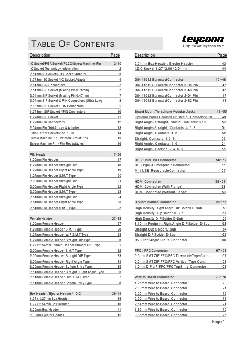
T ABLE O F C ONTENTSPage 1Description PageIC Socket/PGA Socket/PLCC/Screw Machine Pin 2~16IC Socket Technology Information22.54mm IC Sockets / IC Socket Adapter 31.778mm IC Socket / IC Socket Adapter 42.54mm PIN Connectors52.54mm SIP Socket (Mating Pin 0.76mm) 62.54mm SIP Socket (Mating Pin 0.47mm)72.54mm SIP Socket & PIN Connectors (Ultra Low)82.00mm SIP Socket / PIN Connectors 91.778mm SIP Socket / PIN Connectors 101.27mm SIP Socket 111.27mm Pin Connectors122.54mm Pin Grid Arrays & Adapter 13Chip Carrier Sockets for PLCC14Screw Machine Pin - Printed Circuit Pins 15Screw Machine Pin - Pin Receptacles 16PIN Header17~261.00mm Pin Header171.27mm Pin Header Straight DIP 181.27mm Pin Header Right Angle Type 191.27mm Pin Header S.M.T Type 202.00mm Pin Header Straight DIP 212.00mm Pin Header Right Angle Type 222.00mm Pin Header S.M.T Type 232.54mm Pin Header Straight DIP 242.54mm Pin Header Right Angle Type 252.54mm Pin Header S.M.T Type26Female Header27~381.00mm Female Header271.27mm Female Header S.M.T Type 281.27mm Female Header W/P S.M.T Type 291.27mm Female Header Straight DIP Type301.27 x 2.54mm Female Header Straight DIP Type 312.00mm Female Header S.M.T Type322.00mm Female Header Straight DIP Type 332.00mm Female Header Right Angle Type 342.00mm Female Header Bottom Entry Type352.54mm Female Header Straight / Right Angle Type 362.54mm Female Header DIP / S.M.T Type 372.54mm Female Header Bottom Entry Type 38Box Header / Ejector Header / I.D.C 39~441.27 x 1.27mm Box Header 391.27 x 2.54mm Box Header 402.00mm Box Header 412.00mm Ejector Header42Description Page2.54mm Box Header / Ejector Header 43I.D.C Socket:1.27 / 2.00 / 2.54mm 44DIN 41612 Eurocard Connector 45~48DIN 41612 Eurocard Connector 3-96 Pin 45DIN 41612 Eurocard Connector 3-48 Pin 46DIN 41612 Eurocard Connector 2-64 Pin 47DIN 41612 Eurocard Connector 2-32 Pin 48Board Mount Telephone Modular Jacks 49~55 49 50 51 52S 53 54 55USB / Mini USB Connector 56~57USB Type-A Receptacle Connector 56Mini USB Receptacle Connector 57HDMI Connector 58~59HDMI Connector (With Flange) 58HDMI Connector (Without Flange) 59D subminiature Connector 60~66High Density Right Angle DIP Solder D-Sub 60High Density Cup Solder D-Sub 61High Density DIP Solder D-Sub 628.10mm Footprint Right Angle DIP Solder D-Sub 63Straight Cup Solder D-Sub 64Straight DIP Solder D-Sub 65DVI Right A ngle Digital Connector 66FFC / FPC Connector 67~690.5mm SMT ZIF FFC/FPC Downside Type Conn. 670.5mm SMT ZIF FFC/FPC Vertical Type Conn. 681.0mm DIP LIF FFC/FPC Top Entry Connector 69Wire to Board Connector 70~761.25mm Wire to Board Connector 702.00mm Wire to Board Connector 712.00mm Wire to Board Connector 722.50mm Wire to Board Connector 732.54mm Wire to Board Connector 743.96mm Wire to Board Connector 753.96mm Wire to Board Connector 76Optional Panel Ground Out Shield, Contacts: 8,10 Right Angle / Straight, Shield, Contacts: 8,10Right Angle /Straight, Contacts: 4, 6, 8Right Angle, Contacts: 4, 6, 8traight, Contacts: 4, 6, 8Right Angle, Contacts: 4, 6Right Angle, Ports: 1, 2, 4, 6, 8IC socket / PCB Connectors/ PGA Socket / PLCC SocketPitch:2.54mm / 2.00m / 1.778mm /1.27mm / 1.00mmDue to technical progress, all the information provided is subject to change without prior notice. Page 2IC SocketPitch:2.54mmIC Solder AdapterSolder Type, SMT Type, Wire-WrapTechnical Specs:Insulator: Black glass filled polyester PBT-GF30-FR Flammability: UL 94V-OPIN(Sleeve): Brass CuZn36Pb3 (C36000)Contact clip (4 finger): Beryllium copper (C17200)Accepted pin : 0.40 to 0.56 mmForces(IC Socket): (polished steel gauge 0.43 mm) -- Insertion 2 N typ. -- Withdrawal 1 N typ.Mechanical life: min 500 cycles Rated current: 1 AContact resistance: max 10 mDielectric strength: min 1000 V RMS5263.5022.8666.0425.4081.286478.7422.8625.402833.0215.2435.5640.6445.7250.8053.3460.9663.5066.0463.50525048503640423258.4260.9663.5060.9615.2422.8615.2415.2438.1043.1848.2650.8015.2415.2415.2415.2440.6430.48322438.1027.9410.1615.2417.7817.7825.4017.7817.7817.7817.7817.7817.7812.7017.78Dim A Contact Dim B Dim CDim D IC SocketWire - WrapPage 3Due to technical progress, all the information provided is subject to change without prior notice.Technical Specs:Insulator: Black glass filled polyester PBT-GF30-FR Flammability: UL 94V-OPIN (Sleeve): Brass CuZn36Pb3 (C36000)Rated current: 1 AContact resistance: max 10 m1000 V RMSAccepted pin :0.40 to 0.56 mmForces: (polished steel gauge 0.43 mm)-- Insertion 2 N typ.-- Withdrawal 1 N typ.Mechanical life: min 100 cyclesIC Socket:Poles A B C16 14.6 7.62 10.128 25.2 10.16 12.730 27.0 10.16 12.732 28.8 10.16 12.748 43.1 10.16 12.720 18.1 15.24 17.6424 21.7 15.24 17.6428 25.2 15.24 17.6440 35.8 15.24 17.6442 37.7 15.24 17.6448 43.1 15.24 17.6452 46.7 15.24 17.6456 50.2 15.24 17.6464 57.3 15.24 17.6468 60.9 15.24 17.6464* 57.3 19.05 21.5 IC Socket Adapter:IC Socket - Solder Type Pitch:1.778mmIC Socket Adapter - Solder Type Pitch:1.778mmPage 4Due to technical progress, all the information provided is subject to change without prior notice.Flammability: UL 94V-OContact: Brass CuZn36Pb3 (C36000)Connecting pins : 0.47 mmMechanical life: min 500 cycles Rated current: 3 ADielectric strength: min1000 V RMSPage 5Due to technical progress, all the information provided is subject to change without prior notice.Flammability: UL 94V-OSleeve: Brass CuZn36Pb3 (C36000)Contact clip (6 finger): Beryllium copper (C17200)Mating pins:0.70 to 0.90 mm, 0.635 mm Forces: (polished steel gauge 0.76 mm)-- Insertion 2 N typ.-- Withdrawal 1 N typ.Mechanical life: min 500 cycles Rated current: 3 AContact resistance: max 10 mDielectric strength: min 1000 V RMSCoplanarity SMD max 0.1 mm (measured on terminations: 25 mmlong connectors)Page 6Due to technical progress, all the information provided is subject to change without prior notice.2Number of Contacts:Single row = 01 to 40Double row=02 to 803Dip Spacing:0=Single row 1=Double rowOrdering Code2XX 3X 4X 576X 7XX11411Series No.:141=SIP Socket6Plated(Sleeve / Contact):0 = Tin 200u" / Tin 200u"1 = Tin 200u" / Gold Flash 2 = Tin 200u" / Gold 5u"3 = Tin 200u" / Gold 15u"4 = Tin 200u" / Gold 30u"5 = Gold Flash / Gold Flash 5Insulator Height 7=7.00mm4Tail & Mounting Style:S=Straight DIP Type M=Straight S.M.T Type R =Right A ngle Type 7Pin TypeSee Page 15~16Flammability: UL 94V-OSleeve: Brass CuZn36Pb3 (C36000)Contact clip (6 finger): Beryllium copper (C17200)Mating pins:0.40 to 0.56 mmForces: (polished steel gauge 0.43 mm)-- Insertion 2 N typ.-- Withdrawal 1 N typ.Mechanical life: min 500 cycles Rated current: 3 AContact resistance: max 10 mDielectric strength: min 1000 V RMSCoplanarity SMD max 0.1 mm (measured on terminations: 25 mmlong connectors)Page 7Due to technical progress, all the information provided is subject to change without prior notice.2Number of Contacts:Single row = 01 to 40Double row=02 to 803Dip Spacing:0=Single row 1=Double rowOrdering Code2XX 3X 4X 5X 6X 7XX11411Series No.:141=SIP Socket6Plated(Sleeve / Contact):0 = Tin 200u" / Tin 200u"1 = Tin 200u" / Gold Flash 2 = Tin 200u" / Gold 5u"3 = Tin 200u" / Gold 15u"4 = Tin 200u" / Gold 30u"5 = Gold Flash / Gold Flash 5Insulator Height 3=3.00mm4Tail & Mounting Style:S=Straight DIP Type M=Straight S.M.T T ype R =Right A ngle Type 7Pin TypeSee Page 15~16Flammability: UL 94V-OSleeve: Brass CuZn36Pb3 (C36000)Contact clip (6 finger): Beryllium copper (C17200)Mating pins:0.40 to 0.56 mmForces: (polished steel gauge 0.43 mm)-- Insertion 2 N typ.-- Withdrawal 1 N typ.Mechanical life: min 500 cycles Rated current: 3 AContact resistance: max 10 mDielectric strength: min1000 V RMSPage 8Due to technical progress, all the information provided is subject to change without prior notice.2Number of Contacts:Single row = 01 to 40Double row=02 to 803Dip Spacing:0=Single row 1=Double rowOrdering Code2XX 3X 4X 5X 6X 7XX11411Series No.:141=SIP Socket6Plated(Sleeve / Contact):0 = Tin 200u" / Tin 200u"1 = Tin 200u" / Gold Flash 2 = Tin 200u" / Gold 5u"3 = Tin 200u" / Gold 15u"4 = Tin 200u" / Gold 30u"5 = Gold Flash / Gold Flash 5Insulator Height 1=1.30mm 2=1.90mm4Tail & Mounting Style:S=Straight DIP Type M=Straight S.M.T Type R =Right A ngle Type 7Pin TypeSee Page 15~16Flammability: UL 94V-OSleeve: Brass CuZn36Pb3 (C36000)Contact clip (6 finger): Beryllium copper (C17200)Mating pins:0.40 to 0.56 mmForces(SIP Socket): (polished steel gauge 0.43 mm) -- Insertion 2 N typ. -- Withdrawal 1 N typ.Mechanical life: min 500 cycles Rated current: 3 AContact resistance: max 10 mDielectric strength: min1000 V RMSPage 9Due to technical progress, all the information provided is subject to changewithout prior notice.Flammability: UL 94V-OSleeve: Brass CuZn36Pb3 (C36000)Contact clip (6 finger): Beryllium copper (C17200)Mating pins:0.40 to 0.56 mmForces(SIP Socket): (polished steel gauge 0.43 mm) -- Insertion 2 N typ. -- Withdrawal 1 N typ.Mechanical life: min 500 cycles Rated current: 3 AContact resistance: max 10 mDielectric strength: min1000 V RMSPage 10Due to technical progress, all the information provided is subject to change without prior notice.2Number of Contacts:Single row = 01 to 40Double row=02 to 803Dip Spacing:0=Single row 1=Double rowOrdering Code2XX 3X 4X 536X 7XX11X71Series No.:147=SIP Socket Pitch:1.778mm137=PIN Connectors Pitch:1.778mm6Plated(Sleeve / Contact):0 = Tin 200u" / Tin 200u"1 = Tin 200u" / Gold Flash 2 = Tin 200u" / Gold 5u"3 = Tin 200u" / Gold 15u"4 = Tin 200u" / Gold 30u"5 = Gold Flash / Gold Flash 6 = Gold 3u" / Gold 3u"7 = Gold 5u" / Gold 5u"8 = Gold 10u" / Gold 10u"5Insulator Height 3=3.00mm 4Tail & Mounting Style:S=Straight DIP Type M=Straight S.M.T Type R =Right A ngle Type 7Pin TypeSee Page 15~16Flammability: UL 94V-OSleeve: Brass CuZn36Pb3 (C36000)Contact clip (6 finger): Beryllium copper (C17200)Mating pins:0.38 to 0.50 mmForces: (polished steel gauge 0.41 mm) -- Insertion 0.5 N typ. -- Withdrawal 0.2 N typ.Mechanical life: min 500 cycles Rated current: 1 AContact resistance: max 20 m Dielectric strength: min 500 V RMSCoplanarity SMD max 0.1 mm (measured on terminations: 25 mmlong connectors)Page 11Due to technical progress, all the information provided is subject to change without prior notice.Flammability: UL 94V-OContact: Brass CuZn36Pb3 (C36000)Contact pin:•0.41mm Mechanical life: min 500 cycles Rated current: 1 ADielectric strength: min 1000 V RMS Coplanarity SMDterminations: max 0.1 mm (measured on 25 mm longconnectors)Page 12Due to technical progress, all the information provided is subject to change without prior notice.2Number of Contacts:Single row = 01 to 40Double row=02 to 803Dip Spacing:0=Single row 1=Double rowOrdering Code2XX 3X 4X 546X 7XX11331Series No.:133=PIN Connectors Pitch:1.27mm5Insulator Height 2=2.20mm 2=1.90mm 4Tail & Mounting Style:S=Straight DIP Type M=Straight S.M.T T ype R =Right A ngle Type 7Pin TypeSee Page 15~166PIN Plated:0 = Tin 200u" / Tin 200u"5 = Gold Flash / Gold Flash 6 = Gold 3u" / Gold 3u"7 = Gold 5u" / Gold 5u"8 = Gold 10u" / Gold 10u"Pin grid array Socket & AdapterPitch:2.54mmSolder TypeTechnical Specs:Insulator: Black glass filled polyester PBT-GF30-FRFlammability: UL 94V-OSleeve: Brass CuZn36Pb3 (C36000)Contact clip (4 finger): Beryllium copper (C17200)Accepted pin: 0.40 to 0.56 mmForces: (polished steel gauge 0.46 mm)-- Insertion 0.7 N typ.-- Withdrawal 0.4 N typ.Mechanical life: min 100 cyclesRated current: 1 AContact resistance: max 10 mDielectric strength: min 1000 V RMSCalculate with n1 = number of contacts in one line andn2 = characteristic size of the windowA = n1x2.54B = (n1-1)x2.54C = (n2x2.54)-0.40PGA basic body 11X11Number of contacts: 68PGA basic body 13X13Number of contacts: 84PGA basic body 13X13Number of contacts: 121PGA basic body 14X14Number of contacts: 132PGA basic body 17X17Number of contacts: 241PGA basic body 17X17Number of contacts: 169PGA basic body 16X16Number of contacts: 156PGA basic body 15X15Number of contacts: 145PGA basic body 20X20Number of contacts: 400PGA basic body 19X19Number of contacts: 306PGA basic body 19X19Number of contacts: 238PGA basic body 18X18Number of contacts: 225Ordering Code2XXX3X4X5XX6X115X2Number of Contacts:068=68 Pin306=306 Pin......1Series No.:152=Pitch 2.54mm PGA Socket151=Pitch 2.54mm PGA Socket Adapter3PGA basic body sizel:...... 7=7X78=8X8 9=9X90=10X10 A=11X11B=12X12 C=13X13D=14X14 E=15X15......4Insulator Material:1 =2 = PPSFR-4Page 13 Due to technical progress, all the information provided is subject to change without prior notice.6Plated(Sleeve / Contact):0 = Tin 200u" / Tin 200u"1 = Tin 200u" / Gold Flash2 = Tin 200u" / Gold 5u"3 = Tin 200u" / Gold 15u"4 = Tin 200u" / Gold 30u"5 = Gold Flash / Gold Flash6 = Gold 3u" / Gold 3u"7 = Gold 5u" / Gold 5u"8 = Gold 10u" / Gold 10u"7Pin TypeSee Page 15~16PLCC SocketSockets for Plastic Leaded Chip CarriersSMT Terminations / Sollder TypeTechnical Specs:Insulator: Black glass filled polyester PPS-GF30-FRFlammability: UL 94V-OContact: Phosphor bronzeContact pressure: min 1.5 N per contactMechanical life: min 50 cyclesRated current: 1 AContact resistance: max 20 mDielectric strength: min 600 V RMSInsulation resistance: min 5000 MCapacitance: max 2 pFCoplanarity SMDterminations: max 0.1 mmOrdering Code2XX3X45X6X7811296Height over PC Board0=3.80mm1=4.15mm2=4.60mm78Customer Request2Number of Contacts:20,28,32,44,52,68,841Series No.:129=PLCC Chip Carrier Socket5 Packing method:0 = Tube1 = T ape Reel3Tail& Mounting Style:S = Straight DIP TypeM = Straight S.M.T T ype4Body Color:1=BrownPage 14Due to technicalprogress, all the information provided is subject to change without prior notice.SCREW MACHINE PINS----Printed Circuit PinsDue to technical progress, all the information provided is subject to change without prior notice.Page 15SCREW MACHINE PINS----Pin ReceptaclesDue to technical progress, all the information provided is subject to change without prior notice. Page 16SPECIFICATIONS:Current Rating: 1.0 AMPContact Resistance: 30m Max Insulation Resistance: 500M Min Withstand V oltage: 500V AC/minute Operation T emperature: -40 to +105Max Process T emp: 230 for 30~60 secretary.MATERIALS:Contact Material: BrassContact Plating: Gold or Tin over 50Ni Insulator Material: Polyester(UL94V-0) Standard: LCPOrdering CodeSeries No.:3= Pin Header10XXX 918X 7X 6X 5XX 4X 3X 25131Pitch: 5= 1.00mm2Dip Spacing:1=Single row 2=Double row 4Number of Contacts:Single row = 01 to 50Double row=02 to 98 x0=100pin 5Insulator Height: 1 = 1.00mm 5 = 1.50mm3Contact Plated0=Tin 1=Gold Flash 2=Gold 3u" 3=Gold 5u"4=Gold 10u" 5=Gold 15u"6= Gold 30u"7Tail & Mounting Style:S=Straight DIP type M=Straight SMT type6Material Type0=PPS 3=Nylon-66 1=PBT 4=Nylon-6T 2=LCP 5=P A468Tiers of Body 1 = Single tier 2 = Double tier 3 = T riple tier9Pin LengthXXX=A+H+C10Page 17Due to technicalprogress, all the information provided is subject to change without prior notice.SPECIFICATIONS:Current Rating: 1.0 AMPContact Resistance: 30m Max Insulation Resistance: 1000M Min Withstand Voltage: 300VAC/minute Operation Temperature: -40 to +105MATERIALS:Contact Material: BrassContact Plating: Gold or Tin over 50Ni Insulator Material: Polyester(UL94V-0) Standard: PA 46••Ordering CodeSeries No.:3= Pin Header10XXX 9X 857X 6S 5XX 4X 3X 23131Pitch: 3= 1.27mm2Dip Spacing:1=Single row 2=Double row 4Number of Contacts:Single row = 01 to 50Double row=02 to 98 x0=100Pin 5Insulator Height:1 = 1.00mm2 = 2.00mm3 = 2.50mm 5 = 1.50mm 6 = 1.60mm 7 = 1.70mm 8 = 0.80mm 9 = 0.65mm3Contact Plated 0=Tin1=Gold Flash 2=Gold 3u" 3=Gold 5u"4=Gold 10u"5=Gold 15u"6= Gold 30u"7Tail & Mounting Style:S=Straight DIP type6Material Type 2=LCP 3=Nylon-664=Nylon-6T 5=PA468Tiers of Body 1 = Single tier 2 = Double tier 3 = T riple tier9Pin LengthXXX=A+B+C10Page 18Due to technical progress, all the information provided is subject to changewithout prior notice.SPECIFICATIONS:Current Rating: 1.0 AMPContact Resistance: 30m Max Insulation Resistance: 1000M Min Withstand Voltage: 300VAC/minute Operation T emperature: -40 to +105MATERIALS:Contact Material: BrassContact Plating: Gold or Tin over 50Ni Insulator Material: Polyester(UL94V-0) Standard: PA 46••Ordering CodeSeries No.:3= Pin Header10XXX 91857X 6R 5XX 4X 3X 23131Pitch: 3= 1.27mm2Dip Spacing:1=Single row 2=Double row 4Number of Contacts:Single row = 01 to 50Double row=02 to 98 x0=100Pin 5Insulator Height:1 = 1.00mm2 = 2.00mm3 = 2.50mm 5 = 1.50mm 6 = 1.60mm 7 = 1.70mm 8 = 0.80mm 9 = 0.65mm3Contact Plated 0=Tin1=Gold Flash 2=Gold 3u" 3=Gold 5u"4=Gold 10u"5=Gold 15u"6= Gold 30u"7Tail & Mounting Style:R=Right Angle DIP T ype6Material Type 2=LCP 3=Nylon-664=Nylon-6T 5=PA468Tiers of Body 1 = Single tier 2 = Double tier 3 = T riple tier9Pin LengthXXX=A+H+C10Page 19Due to technical progress, all the information provided is subject to changewithout prior notice.SPECIFICATIONS:Current Rating: 1.0 AMPContact Resistance: 30m Max Insulation Resistance: 1000M Min Withstand Voltage: 300VAC/minute Operation Temperature: -40 to +105MATERIALS:Contact Material: BrassContact Plating: Gold or Tin over 50Ni Insulator Material: Polyester(UL94V-0) Standard: PA 46••Ordering CodeSeries No.:3= Pin Header10XXX 9X 8X 7X 6M 5XX 4X 3X 23131Pitch: 3= 1.27mm2Dip Spacing:1=Single row 2=Double row 4Number of Contacts:Single row = 01 to 50Double row=02 to 98 x0=100Pin 5Insulator Height:1 = 1.00mm2 = 2.00mm3 = 2.50mm 5 = 1.50mm 6 = 1.60mm 7 = 1.70mm 8 = 0.80mm 9 = 0.65mm3Contact Plated 0=Tin1=Gold Flash 2=Gold 3u" 3=Gold 5u"4=Gold 10u"5=Gold 15u"6= Gold 30u"7Tail & Mounting Style:M=Straight SMT type6Material Type 2=LCP 3=Nylon-664=Nylon-6T 5=PA468Tiers of Body 1 = Single tier 2 = Double tier 3 = T riple tier9Pin LengthXXX=A+B+C10Page 20Due to technical progress, all the information provided is subject to changewithout prior notice.SPECIFICATIONS:Current Rating: 2.0 AMPContact Resistance: 30m Max Insulation Resistance: 1000M Min Withstand Voltage: 500VAC/minute Operation T emperature: -40 to +105MATERIALS:Contact Material: BrassContact Plating: Gold or Tin over 50Ni Insulator Material: Polyester(UL94V-0) Standard: PA46••Ordering CodeSeries No.:3= Pin Header10XXX 9X 8X 7X 6S 5XX 4X 3X 22131Pitch: 2= 2.00mm2Dip Spacing:1=Single row 2=Double row 4Number of Contacts:Single row = 01 to 40Double row=02 to 80 5Insulator Height: 2 = 2.00mm 5 = 1.50mm3Contact Plated0=Tin 1=Gold Flash 2=Gold 3u" 3=Gold 5u"4=Gold 10u" 5=Gold 15u"6= Gold 30u"7Tail & Mounting Style:S=Straight DIP type6Material Type0=PPS 3=Nylon-66 1=PBT 4=Nylon-6T 2=LCP 5=P A468Tiers of Body 1 = Single tier 2 = Double tier 3 = T riple tier9Pin LengthXXX=A+B+C10Page 21Due to technical progress, all the information provided is subject to changewithout prior notice.SPECIFICATIONS:Current Rating: 2.0 AMPContact Resistance: 30m Max Insulation Resistance: 1000M Min Withstand Voltage: 500VAC/minute Operation Temperature: -40 to +105MATERIALS:Contact Material: BrassContact Plating: Gold or Tin over 50Ni Insulator Material: Polyester(UL94V-0) Standard: PA46••Ordering CodeSeries No.:3= Pin Header10XXX 918X 7X 6R 5XX 4X 3X 22131Pitch: 2= 2.00mm2Dip Spacing:1=Single row 2=Double row 4Number of Contacts:Single row = 01 to 40Double row=02 to 80 5Insulator Height: 2 = 2.00mm 5 = 1.50mm3Contact Plated0=Tin 1=Gold Flash 2=Gold 3u" 3=Gold 5u"4=Gold 10u" 5=Gold 15u"6= Gold 30u"7Tail & Mounting Style:R=Right Angle DIP T ype6Material Type0=PPS 3=Nylon-66 1=PBT 4=Nylon-6T 2=LCP 5=P A468Tiers of Body 1 = Single tier 2 = Double tier 3 = T riple tier9Pin LengthXXX=A+H+C10Page 22Due to technical progress, all the information provided is subject to changewithout prior notice.SPECIFICATIONS:Current Rating: 2.0 AMPContact Resistance: 30m Max Insulation Resistance: 1000M Min Withstand Voltage: 500VAC/minute Operation T emperature: -40 to +105MATERIALS:Contact Material: BrassContact Plating: Gold or Tin over 50Ni Insulator Material: Polyester(UL94V-0) Standard: PA 46••Ordering CodeSeries No.:3= Pin Header10XXX 9X 8X 7X 6M 5XX 4X 3X 22131Pitch: 2= 2.00mm2Dip Spacing:1=Single row 2=Double row 4Number of Contacts:Single row = 01 to 40Double row=02 to 80 5Insulator Height: 2 = 2.00mm 5 = 1.50mm3Contact Plated0=Tin 1=Gold Flash 2=Gold 3u" 3=Gold 5u"4=Gold 10u" 5=Gold 15u"6= Gold 30u"7Tail & Mounting Style:M=Straight SMT type6Material Type0=PPS 3=Nylon-66 1=PBT 4=Nylon-6T 2=LCP 5=P A468Tiers of Body 1 = Single tier 2 = Double tier 3 = T riple tier9Pin LengthXXX=A+B+C10Page 23Due to technical progress, all the information provided is subject to changewithout prior notice.SPECIFICATIONS:Current Rating: 3.0 AMPContact Resistance: 30m Max Insulation Resistance: 1000M Min Withstand Voltage: 600VAC/minute Operation T emperature: -40 to +105MATERIALS:Contact Material: BrassContact Plating: Gold or Tin over 50Ni Insulator Material: Polyester(UL94V-0) Standard: PBT••Ordering CodeSeries No.:3= Pin Header10XXX 9X 8X 7X 6S 5XX 4X 3X 21131Pitch: 1= 2.54mm2Dip Spacing:1=Single row 2=Double row 4Number of Contacts:Single row = 01 to 40Double row=02 to 80 5Insulator Height: 3 = 2.50mm 5 = 1.50mm3Contact Plated0=Tin 1=Gold Flash 2=Gold 3u" 3=Gold 5u"4=Gold 10u" 5=Gold 15u"6= Gold 30u"7Tail & Mounting Style:S=Straight DIP Type6Material Type0=PPS 3=Nylon-66 1=PBT 4=Nylon-6T 2=LCP 5=P A468Tiers of Body 1 = Single tier 2 = Double tier 3 = T riple tier9Pin LengthXXX=A+B+C10Page 24Due to technical progress, all the information provided is subject to changewithout prior notice.SPECIFICATIONS:Current Rating: 3.0 AMPContact Resistance: 30m Max Insulation Resistance: 1000M Min Withstand Voltage: 600VAC/minute Operation T emperature: -40 to +105MATERIALS:Contact Material: BrassContact Plating: Gold or Tin over 50Ni Insulator Material: Polyester(UL94V-0) Standard: PBT••Ordering CodeSeries No.:3= Pin Header10XXX 918X 7X 6R 5XX 4X 3X 21131Pitch: 1= 2.54mm2Dip Spacing:1=Single row 2=Double row 4Number of Contacts:Single row = 01 to 40Double row=02 to 80 5Insulator Height: 3 = 2.50mm 5 = 1.50mm3Contact Plated0=Tin 1=Gold Flash 2=Gold 3u" 3=Gold 5u"4=Gold 10u" 5=Gold 15u"6= Gold 30u"7Tail & Mounting Style:R=Right Angle DIP T ype6Material Type0=PPS 3=Nylon-66 1=PBT 4=Nylon-6T 2=LCP 5=P A468Tiers of Body 1 = Single tier 2 = Double tier 3 = T riple tier9Pin LengthXXX=A+H+C10Page 25Due to technical progress, all the information provided is subject to change without prior notice.SPECIFICATIONS:Current Rating: 3.0 AMPContact Resistance: 30m Max Insulation Resistance: 1000M Min Withstand Voltage: 600VAC/minute Operation T emperature: -40 to +105MATERIALS:Contact Material: BrassContact Plating: Gold or Tin over 50Ni Insulator Material: Polyester(UL94V-0) Standard: PBT••Ordering CodeSeries No.:3= Pin Header10XXX 9X 857X 6M 5XX 4X 3X 21131Pitch: 1= 2.54mm2Dip Spacing:1=Single row 2=Double row 4Number of Contacts:Single row = 01 to 40Double row=02 to 80 5Insulator Height: 3 = 2.50mm 5 = 1.50mm3Contact Plated0=Tin 1=Gold Flash 2=Gold 3u" 3=Gold 5u"4=Gold 10u" 5=Gold 15u"6= Gold 30u"7Tail & Mounting Style:M=Straight SMT type6Material Type0=PPS 3=Nylon-66 1=PBT 4=Nylon-6T 2=LCP 5=P A468Tiers of Body 1 = Single tier 2 = Double tier 3 = T riple tier9Pin LengthXXX=A+H+C10Page 26Due to technical progress, all the information provided is subject to changewithout prior notice.SPECIFICATIONS:Current Rating: 1.0 AMPContact Resistance: 30m Max Insulation Resistance: 500M Min Withstand Voltage: 200VAC/minute Operation T emperature: -40 to +105Max Process Temp: 230 for 30~60 secretary.MATERIALS:Contact Material: Phosphor Bronze Contact Plating: Gold or Tin over 50Ni Insulator Material: Polyester(UL94V-0) Standard: LCP••Ordering CodeSeries No.:2= Female Header100918X 7X 6M 5XX 423225121Pitch: 5= 1.00mm2Dip Spacing:1=Single row 2=Double row 4Number of Contacts:Single row = 01 to 50Double row=02 to 98 x0=100 Pin 5Insulator Height: 2 = 2.0mm3Contact Plated 0=Tin1=Gold Flash 2=Gold 3u"3=Gold 5u"4=Gold 10u"5=Gold 15u"6= Gold 30u"7Tail & Mounting Style:M=Straight SMT type6Material Type 0=PPS 1=PBT 2=LCP 3=Nylon-664=Nylon-6T 5=PA468Color:1=Black9Customer Request10Page 27Due to technicalprogress, all the information provided is subject to change without prior notice.SPECIFICATIONS:Current Rating: 1.0 AMPContact Resistance: 30m Max Insulation Resistance: 1000M Min Withstand Voltage: 300VAC/minute Operation Temperature: -40 to +105MATERIALS:Contact Material: Phosphor Bronze Contact Plating: Gold or Tin over 50Ni Insulator Material: Polyester(UL94V-0) Standard: PA 46••Ordering CodeSeries No.:2= Female Header100918X 7X 6M 5XX 4X 3X 23121Pitch: 3= 1.27mm2Dip Spacing:1=Single row 2=Double row 4Number of Contacts:Single row = 01 to 50Double row=02 to 98 x0=100 Pin 5Insulator Height: 2 = 2.0mm 3 = 3.4mm 4 = 4.3mm 5 = 4.6mm3Contact Plated 0=Tin1=Gold Flash 2=Gold 3u"3=Gold 5u"4=Gold 10u"5=Gold 15u"6= Gold 30u"7Tail & Mounting Style:M=Straight SMT type6Material Type 0=PPS 1=PBT 2=LCP 3=Nylon-664=Nylon-6T 5=PA468Color:1=Black9Customer Request10H = 2.0mm H = 3.4mm H = 4.3mmH = 4.4mmPage 28Due to technical progress, all the information provided is subject to changewithout prior notice.。
J30J系列微型矩形电连接器
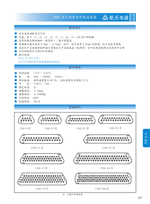
128
J30J 系列微型矩形电连接器
线夹合件族谱树
A1型线夹合件 线夹合件 A2型线夹合件 A3型线夹合件
航天电器
只能与"压接基本型"插头(座)合件配套使用。 只能与J30J-TJ-Q8/ZK-Q8插头(座)合件配套使用。 是"焊接基本型"插头(座)合件的默认配件。 还可与"压接基本型"插头(座)合件配合使用。
129
J30J 系列
航天电器
J30J 系列微型矩形电连接器
订货标志
J30J ①
×
②
- ×
③
TJ/ZK
④
×
×
- ×
×
(附加说明)
⑤ ⑥
⑦ ⑧
① 主称代号: ② 系列改型:不表示 - 基本型 A - 快锁型 C - 外壳材料为锡磷青铜并镀镍 D - 安装孔改为 M2-6H M - 胶密封 M1 - 玻璃烧结密封 ③ 接触件数目:9、15、21、25、31、37、51、66、74、100 ④ 连接器与接触件种类: TJ - 插头装插针 ZK - 插座装插孔 TJ、ZK 为固定搭配 ⑤ 尾端形式: 无字母 - 压接 S - 焊接 N - 直插印制板 W - 弯插印制板 ⑥ 锁紧组件类别:详见 J30J 锁紧组件 ⑦ 表面涂覆: 无字母 - 外壳镀镍 G - 外壳镀镉 ⑧ 基本改型:A - 外壳尾端带屏蔽网线夹 C - 用于产品出线方向与接触件轴向垂直时 D - 插座外壳法兰对接端上带有防转槽 AD - 改型 A 与改型 D 的结合 Q - 外壳法兰加宽 J - 印制板网格间距为 1.27×2.54(列 × 行) 注:附加说明不是订货标志的组成部分,顾客在选用时请在括号中注明压接的导线规格如:导线截面积、 长度和颜色等。有特殊连线要求时,请给出连线关系。
75ΩSMB射频同轴连接器标准
BS9210 F0022
Features/Benefits:
Styles to suit most popular 75 Ohm coaxial cables. Available for telecom standard and HDC distribution frames. Gold Plated contact surfaces.
MIL-STD-202
耐蚀性/Corrosion
材料/Materials
MIL-STD-202
壳体/Housing
黄铜/Brass
中心插针/Center pin
黄铜/Brass
中心接触体/Center Contact
铍铜/Be Cu
压接套管/Crimp Ferrule
铜/Cu
弹簧圈/Spring latch
Locking options prevent accidental disconnection , or ease of disconnection for testing.
Push-Pull self-latching mounting reduces the time needed for fitting to DDFs.
安装方法 Assembly instruction
4521 4531 4541
备注 Notes
弯式软电缆插头/Right Angle Flexible Cable Plugs(male)
适用软电缆/for flexible cables 电缆外导体压接/cable entry crimp 中心导体焊接/centre contact soldered
J30J系列微型矩形电连接器
J30J 系列微型矩形电连接器
J30J压接基本型\J30J-TJ&J30J-ZK
B 14.3 18.2 22 24.5 28.3 32.2 30.86 37.3 33.5 45.7 14.3 18.2 22 24.5 28.3 32.2 30.86 37.3 33.5 45.7 C 7.6 7.6 7.6 7.6 7.6 7.6 8.7 8.7 9.7 9.7 7.6 7.6 7.6 7.6 7.6 7.6 8.7 8.7 9.7 9.7 D 8.3 12.3 16 18.6 22.4 26.3 25 31.4 27.5 35 9.8 13.7 17.4 20 23.8 27.7 26.5 32.9 29 36.6 E 9.9 13.8 17.6 20.2 24 27.8 26.6 33 29.1 36.6 9.9 13.8 17.6 20.2 24 27.8 26.6 33 29.1 36.65 F 4.7 4.7 4.7 4.7 4.7 4.7 5.8 5.8 6.8 6.8 6.1 6.1 6.1 6.1 6.1 6.1 7.2 7.2 8.3 8.2 G 6.8 6.8 6.8 6.8 6.8 6.8 7.9 7.9 9.1 9.1 6.8 6.8 6.8 6.8 6.8 6.8 7.9 7.9 9.1 9.1
产品选用必知事项 选用J30J产品,应同时选择插头(座)合件及锁紧组件,这样才能够选出带有锁紧功能 的插头或插座。而线夹合件不是必选,但可按需决定是否选用。 此外,由于并非所有插头(座)合件、锁紧组件、线夹合件之间都能任意组合搭配以及 产品特点所致,选用J30J产品首先应知晓下列事项:
1、线夹合件选用应按“线夹合件族谱树”规定进行。此外,配装了线夹合件的插头(座)合件不宜配用 板前安装状态的锁紧组件(即安装螺钉适于板前安装的锁紧组件,如 P、P8、P9 等),因为线夹的存在 会使安装板无法安装;配装了线夹合件的插头(座)合件若要配用板后安装状态的锁紧组件(即安装螺 钉适于板后安装的锁紧组件,如 P0、P3、P4、P11 等),须将板的厚度按“安装板厚度 +0.7”来考虑。 2、因焊接基本型插头(座)合件(J30J-TJS/ZKS)默认配装有 A3 型线夹合件,所以在其基础上扩展而 来的 J30J-TJS/ZKS-G 插头(座)合件也要默认配装 A3 型线夹合件。为保持线夹与外壳镀层相同,线夹 也应镀镉。 3、型号中含有大写字母“D”的插头(座)合件不能配装 L、L1 ~ L8、K、K1 型等锁紧组件。 4、型号后端含有大写字母“D”的插头(座)合件如要配装用于板后安装状态的锁紧组件(即安装螺钉 适于板后安装的锁紧组件,如 P0、P3、P4、P11 等)时,必须将板的厚度按“安装板厚度 +0.6”来考虑。 5、J30J-TJ/ZK-Q 插头(座)合件默认配装有法兰盘界面橡胶垫,但该橡胶垫只有在插头(座)合件配装 固定端锁紧组件时才有意义,若插头(座)合件配装自由端锁紧组件则不需该橡胶垫,若插头(座)合 件配装特殊的锁紧组件则需根据锁紧组件是否需与安装板固定来确定是否配用法兰盘界面橡胶垫。但出 于产品状态统一性考虑 , 无论产品所配锁紧组件如何 , 该橡胶垫均与产品配套出厂。 6、第 505 页的压接扩展型中含有大写字母“A”的插头(座)合件均默认在导线束外整体依次套上热缩 管并热缩、屏蔽网,如果不需要则应在合同中注明。如果要求线束最外层套锦纶丝套,也应在合同中注明。 7、若产品的多数孔位都需接外径较粗的导线(如 AFRP-250 或 AFPF-1 屏蔽导线等),则应考虑产品的灌 胶腔及线夹合件(当有时)是否有足够的容纳空间,并且结论通常只有进行试装后才能得出。 8、若产品需压接线芯表面无镀覆导线、或线芯表面镀锡导线、或单芯导线,因压接这类导线的工艺较特 别,所以订货合同应是非标准合同并应在合同中注明导线线芯状况。此类导线主要有 AFR-200 导线、类 似 82A01111 等以 82A 开头的导线、以及软圆铜线等。 9、 产品中的空点处理, 若无技术协议或此前未达成共识的, 均用未压接导线的插孔或插针合件将空点堵上。
J30J 系列微型矩形电连接器——航天电器
J30J 系列
152
J30J 系列微型矩形电连接器
航天电器
线夹合件族谱树
线夹合件
A1型线夹合件 A2型线夹合件 A3型线夹合件
只能与"压接基本型"插头(座)合件配套使用。
只能与J30J-TJ-Q8/ZK-Q8插头(座)合件配套使用。 是"焊接基本型"插头(座)合件的默认配件。 还可与"压接基本型"插头(座)合件配合使用。
J30J 产品族谱树可按插头(座)合件族谱树、锁紧组件族谱树、线夹合件族谱树、以及插头(座)族 谱树分别列出,具体如下:
插头(座)合件族谱树
压接基本型 压接扩展型
插头合件或插座合件 插装印制板基本型 插装印制板扩展型 焊接基本型
(J30J-TJ/ZK)
-C -D -G -Q -Q8 (9.6) (11.6) -A
■ 插头 ■ J30J-9、15、21、25、31、37、51、66、74、100TJ-C
A
B
C
D
E
F
G
19.6
14.3
7.6
8.3
9.9
4.7
6.8
23.5
18.2
7.6
12.3
13.8
4.7
6.8
27.4
22
7.6
16
17.6
4.7
6.8
29.8
24.5
7.6
18.6
20.2
4.7
6.8
33.6
28.3
7.6
22.4
24
4.7
6.8
37.4
32.2
7.6
26.3
27.8
J30J 系列微型矩形电连接器——航天电器
30.86
8.7
25
26.6
5.8
7.9
42.9
37.3
8.7
31.4
33
5.8
7.9
38.8
33.5
9.7
27.5
29.1
6.8
9.1
54.7
45.7
9.7
35
36.6
6.8
9.1
19.6
14.3
7.6
9.8
9.9
6.1
6.8
23.5
18.2
7.6
13.7
13.8
6.1
6.8
27.4
22
7.6
17.4
2、因焊接基本型插头(座)合件(J30J-TJS/ZKS)默认配装有 A3 型线夹合件,所以在其基础上扩展而 来的 J30J-TJS/ZKS-G 插头(座)合件也要默认配装 A3 型线夹合件。为保持线夹与外壳镀层相同,线夹 也应镀镉。
3、型号中含有大写字母“D”的插头(座)合件不能配装 L、L1 ~ L8、K、K1 型等锁紧组件。
J30J 系列微型矩形电连接器
航天电器
特点简介
■ 对应美国 MDM 系列产品 ■ 芯数:有 9、15、21、25、31、37、51、66、74、100 芯十种规格 ■ 采用绞线式弹性插针(麻花针),接点密度高 ■ 导线线芯截芯面积 0.1mm2 ~ 0.15mm2。此外,还可采用 0.07mm2 的导线,但产品型号特殊 ■ 本系列产品的锁紧组件按订货要求与产品组装在一起供货,如不需锁紧组件应在合同中注明 ■ 产品性能符合 GJB2446 的要求 ■ 执行标准:
(J30J-TJN/ZKN) (J30J-TJN-J/ZKN-J) (J30J-TJW/ZKW) (J30J-TJW-J/ZKW-J)