(DVFS), Process-Driven Voltage Scaling (PDVS),
DYNAMIC VOLTAGE FREQUENCY SCALING (DVFS) FOR MICROPROCESSORS POWER AND ENERGY REDUCTION
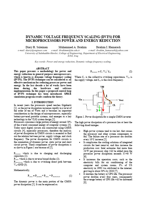
DYNAMIC VOLTAGE FREQUENCY SCALING (DVFS) FORMICROPROCESSORS POWER AND ENERGY REDUCTIONDiary R. Suleiman Muhammed A. Ibrahim Ibrahim I. Hamarash e-mail: diariy@ e-mail: ibrahimm@.tr e-mail: ibrahim_hamarash@ University of Salahaddin-Hawler, College of Engineering, Department of Electrical Engineering,Erbil, IraqKey words: Power and energy reduction, Dynamic voltage frequency scaling,ABSTRACTThis paper presents a methodology for power and energy reduction in general purpose microprocessors, which is known as dynamic voltage frequency scaling (DVFS). The DVFS technique can be considered as an effective mechanism for reducing processor power and energy. In the last decade a lot of works have been done during the hardware and software implementation. In this paper a proposed control loopof DVFS technique has been introduced. SPICE simulation program results confirm the theory.I. INTRODUCTIONIn recent years the processors speed reaches Gigahertz [1], so the power dissipation increases rapidly in a level of the order of ten of Watts and it becomes an important consideration in the design of microprocessors, especially battery-powered portable systems, and emerges as a key technology in the VLSI system design [2].Processors consume a large portion of energy around 50%of the overall consumed energy of computer systems [3]. Today most digital circuits are constructed using CMOS circuits [4], especially processors, therefore the analysis of power dissipation in CMOS circuits is essential to find out the relation between power, supply voltage, and clock frequency. The power dissipation for CMOS circuits is the summation of dynamic power, static power and short circuit power. These components of power dissipation is as shown in Figure 1 are because of [5],P dynamic which is due to charging and discharging capacitors (1).P static which is due to reverse biased diodes (2).P shortcircuit which is due to switching direct path betweenV dd-GND (3).Mathematically,P cmos = P dynamic+ P static + P shortcircuit (1) The dynamic power is the main portion of the CMOS power dissipation [5]. It can be expressed as: P dynmaicα C L V dd2 f clk (2)Where C L is the collective switching capacitance, V dd is the supply voltage, and f clk is the clock frequency.Figure 1. Power dissipation for a simple CMOS inverter The high power dissipation of a processor has at least the following disadvantages:•High power systems tend to run hot, that causes the processor and other system components tofail. The failure rate of a processor are doublesevery 10o C increase [5].•It complicates the cooling solutions of integrated circuits for heat removal, and thus increase theproduction cost. Intel estimates that more than1$/W per processor chip will be added once theprocessor power dissipation exceeds 35-40 W[6].•It increases the operation costs; such as the electricity bills for air conditioning of thecomputer and system rooms. 8% of USelectricity in 1998 was attributed to the internet,growing to about 30% by 2020 [7].•It shortens the battery or UPS life. The processor power doubles every four years, consequentlythe average battery or UPS life will be shortened[8].•It endangers the human body. Current high performance processors consume around 70-100W [7].The major processor manufactures (Intel) has announced that the processor power dissipation doubles every four years [7], therefore dynamic voltage frequency scaling technique, by lowering the supply voltage, is effective in reducing power dissipation. Lowering the supply voltage restricts the operating frequency accordingly because,(f clk α (V dd - V t )2/ V dd ) (3)Where V t is the CMOS threshold voltage.Meaning that changes in frequency are accompanied by appropriate adjustment in voltage.The energy consumption of a program can be reduced by: reducing the number of operation performed, reducing the switching capacitance of each operation, or by reducing the voltage at which these operations are performed [9].There has been a significant amount of research relating to hardware support for dynamic voltage frequency scaling. T. Burd presented a voltage scaling hardware loop [2]. Tiware et. al. presented a hardware technique for shutting down unused hardware modules [6]. Throughout this paper a new dynamic voltage frequency scaling (DVFS) control loop is presented which has a high performance due to its accuracy in progress.II. ANALYSIS OF DVFS TECHNIQUEDynamic voltage frequency scaling (DVFS) is accepted as a technique to reduce power and energy consumption of microprocessors [7]. Lowering only the operating frequency f clk can reduce the power consumption but the energy consumption remains the same because the computation needs more time to finish. Lowering the supply voltage V dd can reduce a significant amount of energy because of the quadratic relation between power and V dd as given in Equation 2. Lowering the supply voltage and operating frequency reduces the power and energy consumption further. Figure 2 shows the power saving achievable by using variable V dd .Figure 2. Power saving achievable byUsing variable VddWhen the clock frequency f clk is reduced by half, this lowers the processor’s power consumption and still allows task to complete by deadline, the energy consumption remains the same. Reducing the voltage level V dd by half reduces the power level further without any corresponding increase in execution time. As a result the energy consumption is reduced significantly, but the appropriate performance is remained [10]. This is shown in Figure 3:Figure 3. Energy consumption vs. power consumption fora task, which is ready at 0 and complete at T, withmaximum clock frequency f clkThere are three key components for implementing DVFS technique in processors [7,10]:1. An operating system which intelligently vary the processor speed.2. A control loop which generates the voltage required for the desired speed.3. A microprocessor which operates over a range of voltages.The relationship between these three components is shown in Figure 4.Figure 4. DVFS required componentsIII. WORKLOAD PREDICTIONTo perform this multi-speed functionality of a processorthe modern operating system will intelligently vary theprocessor speed by predict and estimate the futureworkload of the processor and convert it to a digital word(f des) and save it into a register, whose value is then usedby the control loop to adjust the processor clockfrequency (f clk) with the voltage level (V dd)[11].Figure 5, shows a typical workload pattern with asequence of tasks and deadlines between the tasks. Byscaling down the voltage, each task is extended into theidle time after it, as shown in Figure 6:Figure 5. A typical workload pattern with tasks and idletime between tasks.Figure 6. A typical workload pattern with DVFStechniqueA processor usually goes to sleep as a result of certainspecial instruction, and then it is woken up by certaininterrupts, this cause producing idle intervals between thetasks [11]. Therefore, work load of the processor usuallyconsists of sequence of tasks and idles between tasks. Byscaling down the voltage and frequency each task isextended into the idle time after it. As long as the tasks donot overlap, the dynamic voltage frequency scaling(DVFS) technique is guaranteed to be correct.Before design the DVFS technique it is essential to modelthe workload. The concept of an event makes partitioningthe workload to be possible. Two parameters, α and β asshown in figure 7, are used to describe an event; both inthe unit of time, α measures the length of an event and βmeasures the length of an event plus idle time before thenext event starts. It follows that utilization can bedetermined by dividing α by β. For example if utilizationis 50 percent, it means that this particular event has thepotential to be scaled down by a factor of two [11,12].Figure 7: Modelling the workload with DVFS (ideal case)IV. THE PROPOSED DVFS CONTROL LOOPA control loop, shown in Figure 8 is proposed in thispaper to carry out the appropriate voltage via thefrequency.The operation of this control loop is depending on thedifference between the clock frequency f clk from VCO andf des from the operating system predictor, where the outputof the VCO, f clk, clocks a counter which is reset at 1MHzintervals. This provides a digital word f meas, and it saved ina register. This value is subtracted from the desired clockfrequency f des (which is predicted by the operatingsystem as a digital word and saved in a register) togenerate an error frequency value, f err, and is saved inanother register. This register has to have an additional bitthan the other registers to indicate the sign. This errorword will be converted to voltage levels via a digitalcircuit. The voltage levels are converted to a DC voltageby digital to analog converter (DAC) to be used by acomparator to generate a PWM pulses and then to drivethe DC-DC converter.Figure 8. A proposed DVFS control loopThe feed back loop sets V dd to make f err zero The DC-DCconverter converts the output DC voltage to a leveldepending on the incoming pulses from PWM in thecontrol loop. The VCO(ring oscillator) converts theoutput of the DC-DC converter to a clock frequency. TheDC-DC converter output with the generated clockfrequency is fed to the processor.The proposed DVFS control loop has been simulatedUsing Pspice simulator program. The followingwaveforms are obtained.For f clk=500 MHz and f des=300MHz, the input and outputvoltages of PWM, DC-DC converter, and VCO signalsare shown in the Figure 9,10, and 11respectively.Also, for f clk=300 MHz and f des=500MHz, the input andoutput voltages of PWM, DC-DC converter, and VCOsignals are shown in the Figure 12,13, and 14respectively.Figure 9. The PWM input (V1), output (V2), andsawtooth signal (V3) for f clk=500 MHz and f des=300MHz.Figure 10. The DC-DC converter output voltage (V4) forf clk=500 MHz and f des=300MHzFigure 11. The VCO output signal for f clk=500 MHz andf des=300MHzFigure 12. The PWM input (V1), output (V2), andsawtooth signal (V3) for f clk=300 MHz and f des=500MHzFigure 13. The DC-DC converter output voltage (V4) forf clk=300 MHz and f des=500MHzFigure 14. The VCO output signal for f clk=300 MHz andf des=500MHV. CONCLUSIONThe proposed dynamic voltage frequency scaling (DVFS) loop, which is introduced throughout this work, is to vary or set the supply voltage V dd and operating frequency f clk according to the desired frequency f des which is predicted via the operating system and speed control circuit.The DVFS proposed loop has a high performance due to accuracy in progress, and can significantly improve processor energy efficiency especially for general purpose microprocessors, multimedia interface systems, and battery or UPS powered electronic devices.The presented technique can decreases the processors average energy consumption at runtime depending on the applications and the limit of the supply voltage V dd. Therefore, this proposed DVFS technique can be considered as a critical constraint for the current and future processor’s performance.REFERENCES1. A. Azevedo, I. Issenin, R. Cornea, R. Gupta, N. Dutt,A. Veidenbaum, A. Nicolau, Profile-based DynamicVoltage Scheduling using Program Checkpoints, In Proceedings of Design, Automation and Test in Europe Conference and Exhibition (DATE), March 2002.2.T. D. Bord, Energy-Efficient Processor SystemDesign, Ph. D. Dissertation, University of California,Berkeley, USA, 2001.3.T. Pering, T. Burd, and R. Brodersen, DynamicVoltage Scaling and the Design of a Low-Power Microprocessor System, University of California Berkeley, Electronics Research Laboratory./~pering/lpsw4.I. Hong, D. Kirovski, G. Qu, M. Potkonjak, and M.B. Srivastava, Power Optimization of Variable-Voltage Core-Based Systems, IEEE Transactions on Computer-Aided Design of Integrated Circuits and Systems, Vol.18, No.12, Pages 1702-1714, 1999.5.O. Ergin, Circuit Techniques for Power-AwareMicroprocessors, Master Thesis, The State Universityof New York, USA, 2003.6.V. Tiwari, D. Singh, S. Rajgopal, G. Mehta, R. Patel,and F. Baez, Reducing Power in High-performance Microprocessors, In Proceedings of the 35th Conference on Design Automation, ACM, USA, June1998.7. C. H. Hsu, Compiler-Directed Dynamic Voltage andFrequency Scaling for CPU Power and Energy Reduction, Ph. D. Dissertation, the State University of New Jersey, USA, 2003.8. A. P. Chandrakasan, Low-Power CMOS digitalDesign, IEEE Journal of Solid-State Circuits, Vol.27,No.4, Pages 473-484, April 1992.9.R. Gonzalez and M. Horowitz, Energy Dissipation InGeneral Purpose Microprocessors, IEEE Journal of Solid-State Circuits, Vol.31, No.9, pages 1277-1284,1996. 10.N. Tuaycharoen, RTOS-Based Dynamic VoltageScaling, Master Thesis University of Maryland, 2003.11.K. Choi, K. Dantu, W. Chung Cheng, and M. PedramFrame-Based Dynamic Voltage and Frequency Scaling for a MPEG Decoder, from Boston-University./pubs/software.html#system-player 12.H. So, and A. Woo, A Simple Energy Saving Schemeon PDA’s Using Hardware Scheduled DVS, University of California, Berkeley, Department of Computer Science./~awoo/cs252/report.html。
dvfs工作流程

dvfs工作流程动态电压频率调整(Dynamic Voltage Frequency Scaling,DVFS)是一种针对计算机系统的功耗优化技术。
DVFS通过调整处理器的电压和频率来平衡性能和能效之间的关系。
本文将介绍DVFS的工作流程及其在能源管理中的应用。
在计算机系统中,处理器的电压和频率是可调的。
通常情况下,处理器运行在最高的电压和频率上以获得最佳的性能。
然而,高电压和频率会导致功耗的增加,从而消耗过多的能量和产生过多的热量。
为了平衡性能和能效之间的关系,DVFS技术被引入。
DVFS技术的工作流程如下:1. 监测:DVFS开始时,系统会持续监测处理器的工作负载和功耗情况。
这可以通过硬件传感器或软件监控工具来实现。
监测可以提供处理器当前的性能需求和功耗水平。
2. 分析:基于监测到的数据,系统会进行分析以确定最佳的电压和频率设置。
分析的目标是使得处理器在保持足够性能的同时尽可能地减少功耗。
3. 调整:一旦分析完成,系统会根据结果来调整处理器的电压和频率。
调整可以通过软件控制器、电源管理单元或相关硬件实现。
4. 反馈:调整后,系统会继续监测处理器的性能和功耗情况,并收集反馈信息。
这可以用于评估电压和频率设置的有效性,并对下一次调整进行参考。
5. 循环:DVFS工作流程是一个循环过程,它持续重复监测、分析、调整和反馈的步骤。
这可以确保系统能够根据实时需求动态地调整处理器的电压和频率。
DVFS技术在能源管理中有广泛的应用。
以下是几个例子:1. 移动设备:在移动设备领域,如智能手机和平板电脑中,DVFS技术可以帮助延长电池使用时间。
通过根据应用需求和用户行为调整处理器的电压和频率,系统可以在需要高性能时提供更高的电压和频率,而在轻负载或待机状态下降低电压和频率,以节省能量。
2. 数据中心:在大规模的数据中心中,DVFS技术可以帮助降低能源消耗和运行成本。
通过动态地调整服务器处理器的电压和频率,系统可以根据负载情况实现能效优化。
摩尔线程功耗-概述说明以及解释

摩尔线程功耗-概述说明以及解释1.引言1.1 概述摩尔线程(Moore's Law) 是由英特尔创始人戈登·摩尔提出的一个著名的观察和预测,指出集成电路上可容纳的晶体管数量每隔18至24个月便会翻倍,而且与时间呈指数增长的趋势。
摩尔线程力量是计算机行业长期以来技术发展和创新的重要动力之一。
随着摩尔线程的进一步发展,现代计算机系统中的处理器核心数量不断增加,意味着越来越多的任务可以并行执行,从而提高了计算机的整体性能。
然而,随着摩尔线程的延续,一个重要的问题逐渐浮现,那就是功耗的增长。
随着晶体管数量的增加和集成度的提高,芯片的功耗也在快速增加,这对电池供电设备和散热系统带来了极大的挑战。
因此,了解和研究摩尔线程对功耗的影响并寻找功耗优化的方法成为了当下亟需解决的问题。
通过优化芯片的设计和制造工艺,降低摩尔线程的功耗,可以延长电池寿命,降低电脑系统的散热需求,提高整体能效。
本文将深入探讨摩尔线程的定义和原理,分析摩尔线程对功耗的影响,并提出一些优化方法来减少功耗。
通过对摩尔线程功耗的重要性进行总结,展望未来摩尔线程的发展,并得出本文的结论。
1.2文章结构文章结构部分内容:本文主要通过对摩尔线程功耗的探讨,旨在分析摩尔线程在计算机系统中对功耗的影响,并提出相应的优化方法。
文章主要分为三个部分,分别是引言、正文和结论。
在引言部分,将首先对摩尔线程进行概述,介绍其定义和原理,为读者提供对摩尔线程的基本了解。
接着,会总结文章的结构,明确阐述各个部分的内容安排。
最后,明确本文的目的,即通过对摩尔线程功耗的研究,探讨其重要性和未来发展前景。
正文部分将分为三个小节。
首先,会详细介绍摩尔线程的定义和原理,解释其在计算机系统中的具体作用和工作原理。
其次,将讨论摩尔线程对功耗的影响,分析其可能导致的功耗增加的原因和影响范围。
最后,将提出一些摩尔线程功耗的优化方法,通过降低功耗来提高系统的能效和性能。
结论部分将对全文进行总结,强调摩尔线程功耗的重要性,并对未来摩尔线程的发展进行展望。
超级计算机的功耗控制方法与技术分析

超级计算机的功耗控制方法与技术分析随着信息技术的飞速发展,人类的计算需求也越来越大,这就导致了越来越多的计算机被制造出来。
而其中,一些最先进的计算机被称为超级计算机。
超级计算机具有极高的计算能力,可以在短时间内处理大量数据和计算任务。
然而,超级计算机也存在一个严重的问题,那就是能源消耗。
为了保证计算机长时间稳定运行,需要耗费大量电能,并且在大规模的数据中心中,能源消耗是一个非常显著的成本。
因此,超级计算机的功耗控制已经成为了一个亟待解决的问题。
目前,对于超级计算机的功耗控制,通常采用以下几种方法。
一、动态电压频率调节技术动态电压频率调节技术(Dynamic Voltage Frequency Scaling, DVFS)是一种可以实时动态调节处理器电压和频率的技术。
这种技术可以根据任务的负载程度和运行时间,适当降低处理器的电压和频率,以达到节能的效果。
例如,在执行一些轻量级的任务时,处理器的工作负载可以比较低,并不需要最高功耗的处理能力。
此时,就可以通过DVFS 技术适当降低处理器的电压和频率,以达到节能的效果。
反之,在执行一些重量级的计算任务时,则需要提高处理器的电压和工作频率,以保证计算性能和计算稳定性。
二、睡眠模式睡眠模式技术是超级计算机能源节约的另一种有效方法。
当超级计算机在闲置状态时,可以将系统节点设置为休眠状态,减少节点的功耗。
实际上,休眠状态下,计算机节点的最大功率消耗只有待机状态下的1%左右。
需要明确的是,休眠模式的切换需要耗费一定的时间,不应当在短时间内频繁切换。
如果超级计算机的任务负载较为逐渐,可以将空闲节点设置为休眠状态以达到更加显著的节能效果。
三、硬件节能技术在超级计算机的硬件设计过程中,可以采用一些节能技术来减少能源消耗。
例如,可以采用一些先进的芯片技术,比如CPU能耗架构的设计改进、高效能的内存存储器、更加灵活的交换机和路由器等。
同时,可以采用节能的组件设计,比如使用能源更稳定的电源导线、较小的电源管理芯片等等。
芯片设计中的功耗优化技术有哪些创新

芯片设计中的功耗优化技术有哪些创新在当今的科技时代,芯片作为各种电子设备的核心组件,其性能和功耗表现至关重要。
随着芯片制程的不断缩小以及功能的日益复杂,功耗优化成为了芯片设计中的关键挑战。
为了满足市场对低功耗、高性能芯片的需求,科研人员和工程师们不断探索创新的功耗优化技术。
首先,我们来谈谈动态电压频率调整(DVFS)技术。
这一技术就像是给芯片安装了一个智能的“能量调节器”。
它根据芯片的工作负载动态地调整电压和频率。
当芯片处理的任务较为简单,负载较轻时,降低电压和频率,从而减少功耗;而当任务复杂、负载较重时,相应地提高电压和频率,以保证性能。
这种动态调整的方式在不牺牲太多性能的前提下,有效地降低了芯片的平均功耗。
再来说说多阈值电压(MultiVt)技术。
芯片中的晶体管具有不同的阈值电压,较高阈值电压的晶体管漏电电流小,功耗低,但开关速度较慢;较低阈值电压的晶体管则相反。
通过在芯片设计中合理地混合使用不同阈值电压的晶体管,可以在关键路径上使用低阈值电压的晶体管来保证性能,而在非关键路径上使用高阈值电压的晶体管来降低功耗。
电源门控(Power Gating)技术也是一项重要的创新。
它就像是给芯片的某些部分装上了“电源开关”。
当这些部分暂时不工作时,直接切断电源供应,从而极大地减少了漏电功耗。
这种技术可以有效地控制芯片中不活跃模块的功耗,提高整体的能效。
此外,还有一种叫做体偏置(Body Bias)的技术。
通过对晶体管的体区施加不同的电压,可以改变晶体管的阈值电压和电流特性。
正向体偏置可以提高晶体管的性能,而反向体偏置则可以降低漏电电流,从而达到功耗优化的目的。
在芯片的架构设计方面,也有一些创新的功耗优化方法。
比如,采用异步电路设计。
传统的同步电路中,时钟信号在整个芯片中同步传播,会消耗大量的能量。
而异步电路则没有统一的时钟,各个模块根据自身的需求进行操作,减少了时钟相关的功耗。
另外,存储单元的功耗优化也不容忽视。
(DVFS), Process-Driven Voltage Scaling (PDVS),
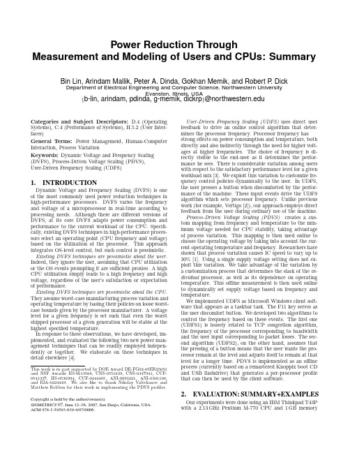
Power Reduction ThroughMeasurement and Modeling of Users and CPUs:SummaryBin Lin,Arindam Mallik,Peter A.Dinda,Gokhan Memik,and Robert P.DickDepartment of Electrical Engineering and Computer Science,Northwestern UniversityEvanston,Illinois,USA{b-lin,arindam,pdinda,g-memik,dickrp}@Categories and Subject Descriptors: D.4(Operating Systems),C.4(Performance of Systems),H.5.2(User Inter-faces)General Terms:Power Management,Human-Computer Interaction,Process VariationKeywords:Dynamic Voltage and Frequency Scaling (DVFS),Process-Driven Voltage Scaling(PDVS),User-Driven Frequency Scaling(UDFS)1.INTRODUCTIONDynamic Voltage and Frequency Scaling(DVFS)is one of the most commonly used power reduction techniques in high-performance processors.DVFS varies the frequency and voltage of a microprocessor in real-time according to processing needs.Although there are different versions of DVFS,at its core DVFS adapts power consumption and performance to the current workload of the CPU.Specifi-cally,existing DVFS techniques in high-performance proces-sors select an operating point(CPU frequency and voltage) based on the utilization of the processor.This approach integrates OS-level control,but such control is pessimistic. Existing DVFS techniques are pessimistic about the user. Indeed,they ignore the user,assuming that CPU utilization or the OS events prompting it are sufficient proxies.A high CPU utilization simply leads to a high frequency and high voltage,regardless of the user’s satisfaction or expectation of performance.Existing DVFS techniques are pessimistic about the CPU. They assume worst-case manufacturing process variation and operating temperature by basing their policies on loose worst-case bounds given by the processor manufacturer.A voltage level for a given frequency is set such that even the worst shipped processor of a given generation will be stable at the highest specified temperature.In response to these observations,we have developed,im-plemented,and evaluated the following two new power man-agement techniques that can be readily employed indepen-dently or together.We elaborate on these techniques in detail elsewhere[4].This work is in part supported by DOE Award DE-FG02-05ER25691 and NSF Awards IIS-0613568,CNS-0551639,CNS-0347941,CCF-0541337,IIS-0536994,CCF-0444405,ANI-0093221,ANI-0301108, and EIA-0224449.We also like to thank Nikolay Valtchanov and Matthew Robben for their work in implementing the PDVS profiler. Copyright is held by the author/owner(s).SIGMETRICS’07,June12–16,2007,San Diego,California,USA.ACM978-1-59593-639-4/07/0006.User-Driven Frequency Scaling(UDFS)uses direct user feedback to drive an online control algorithm that deter-mines the processor frequency.Processor frequency has strong effects on power consumption and temperature,both directly and also indirectly through the need for higher volt-ages at higher frequencies.The choice of frequency is di-rectly visible to the end-user as it determines the perfor-mance he sees.There is considerable variation among users with respect to the satisfactory performance level for a given workload mix[3].We exploit this variation to customize fre-quency control policies dynamically to the user.In UDFS, the user presses a button when discomforted by the perfor-mance of the machine.These input events drive the UDFS algorithm which sets processor frequency.Unlike previous work(for example,Vertigo[2]),our approach employs direct feedback from the user during ordinary use of the machine. Process-Driven Voltage Scaling(PDVS)creates a cus-tom mapping from frequency and temperature to the min-imum voltage needed for CPU stability,taking advantage of process variation.This mapping is then used online to choose the operating voltage by taking into account the cur-rent operating temperature and frequency.Researchers have shown that process variation causes IC speed to vary up to 30%[1].Using a single supply voltage setting does not ex-ploit this variation.We take advantage of the variation by a customization process that determines the slack of the in-dividual processor,as well as its dependence on operating temperature.This offline measurement is then used online to dynamically set supply voltage based on frequency and temperature.We implemented UDFS as Microsoft Windows client soft-ware that appears as a taskbar task.The F11key serves as the user discomfort button.We developed two algorithms to control the frequency based on these events.Thefirst one (UDFS1)is loosely related to TCP congestion algorithm, the frequency of the processor corresponding to bandwidth and the user input corresponding to packet losses.The sec-ond algorithm(UDFS2),on the other hand,assumes that the pressing of a button means that the user wants the pro-cessor remain at the level and adjusts itself to remain at that level for a longer time.PDVS is implemented as an offline process(currently based on a remastered Knoppix boot CD and USBflashdrive)that generates a per-processor profile that can then be used by the client software.2.EV ALUATION:SUMMARY+EXAMPLES Our experiments were done using an IBM Thinkpad T43P with a2.13GHz Pentium M-770CPU and1GB memoryFigure1:Comparison of UDFS algorithms, UDFS+PDVS,and Windows XP DVFS(CPU Dy-namic Power)for the3D Shockwave animation. running Microsoft Windows XP Professional SP2.We ran a study with20users.The user study took around45minutes for each user.Each user was asked perform the following tasks for both UDFS algorithms:Microsoft PowerPoint plus music(4minutes);3D Shockwave animation(4minutes); and FIFA Soccer(8minutes).Our studies also included multitasking scenarios.We measure the overall system power and temperature reduction caused by our methods,and derive the CPU dy-namic bining PDVS and UDFS schemes reduces measured system power by49.9%(27.8%PDVS,22.1%UDFS), averaged across all our users and applications,compared to the Windows XP DVFS scheme.The average temperatureof the CPU is decreased by13.2◦ing user trace-driven simulation to evaluate the CPU in isolation,wefind average CPU dynamic power savings of57.3%(32.4%PDVS,24.9% UDFS),with a maximum reduction of83.4%.In a multi-tasking environment,the CPU dynamic power is reduced by 75.7%on average.We now present a sampling of our results. 2.1CPU Dynamic PowerBecause we do not have hardware to directly measure CPU power,we collect the time series of CPU frequency over time during the user studies and combine it with theoffline PDVS profile(or the nominal voltage settings from the processor datasheet)to derive the CPU dynamic power. Figure1presents both individual user results and aver-age results for both UDFS algorithms,with and without PDVS,for the Shockwave animation.This task elicits the widest range of responses from users,while FIFA Socceris similar and PowerPoint is much more uniform(and has very high power improvements).Although there is variation from user to user,we reduce power by55.1%on average. UDFS1and UDFS2independently reduce the power con-sumption by15.6%and32.2%,er17with UDFS1is anomalous.This user wanted the system to per-form better than the hardware permitted and thus pressed the button virtually continuously even when the CPU was running at the highest frequency.Adding PDVS lowers average power consumption significantly across the board. The power is reduced by49.2%(UDFS1+PDVS)and61.0% (UDFS2+PDVS)in the combined scheme.2.2System Power and TemperatureWe are able to measure the system power of the laptop by replaying the traces from our user study while the laptop is connected to a National Instruments6034E data acquisition board attached to a host workstation.Figure2:Comparison of UDFS algorithms, UDFS+PDVS,and Windows XP DVFS(Measured system power with display off)for the3D Shock-wave animation.Figure2presents results for the UDFS algorithms with and without PDVS,showing the system power savings over the default Windows DVFS approach for the3D Shock-wave animation.UDFS1and UDFS2reduce the average power consumption by17.2%and33.6%,ing UDFS together with PDVS increases average power savings to over50%over the default Windows DVFS scheme.3.CONCLUSIONWe have identified processor and user pessimism as key factors holding back effective power management for proces-sors with support for DVFS.In response,we have developed and evaluated the following new,process-and user-adaptive DVFS techniques:process-driven voltage scaling(PDVS) and user-driven frequency scaling(UDFS).Extensive user studies show that our techniques result in dramatic power savings over the widely used Windows DVFS scheme.Fur-thermore,CPU temperatures can be markedly decreased through the use of our techniques.PDVS can be readily used along with any existing frequency scaling approach, while UDFS depends on user feedback.4.REFERENCES[1]Borkar,S.,Karnik,T.,Narendra,S.,Tschanz,J.,Keshavarzi,A.,and De,V.Parameter Variations and Impact on Circuits and Microarchitecture.InProceedings of the ACM/IEEE Design AutomationConference(DAC)(2003).[2]Flautner,K.,and Mudge,T.Vertigo:AutomaticPerformance-Setting for Linux.In Proceedings of the5th Symposium on Operating Systems Design andImplementation(OSDI)(December2002).[3]Gupta,A.,Lin,B.,and Dinda,P.A.Measuring andUnderstanding User Comfort with Resource Borrowing.In Proceedings of the13th IEEE InternationalSymposium on High Performance DistributedComputing(HPDC2004)(June2004).[4]Mallik,A.,Lin,B.,Dinda,P.,Memik,G.,andDick,R.Process and user driven dynamic voltage and frequency scaling.Tech.Rep.NWU-EECS-06-11,Department of Electrical Engineering and ComputerScience,Northwestern University,August2006.。
dvfs的工作流程
DVFS的工作流程一、概述动态电压频率调节(Dynamic Voltage and Frequency Scaling,简称DVFS)是一种通过调整处理器的电压和频率来实现节能和性能优化的技术。
它可以根据处理器的负载情况,动态地调整电压和频率,以在不降低性能的情况下降低功耗。
本文将详细介绍DVFS的工作流程。
二、DVFS的基本原理DVFS的基本原理是根据处理器的负载情况来调整电压和频率。
当处理器处于高负载状态时,可以提高电压和频率以提供更好的性能;而在低负载状态下,可以降低电压和频率以节省能量。
这种动态调整可以根据实际需求进行,以平衡性能和功耗的关系。
三、DVFS的工作流程DVFS的工作流程可以分为以下几个步骤:1. 监测负载情况DVFS需要实时监测处理器的负载情况,以便根据负载情况进行电压和频率的调整。
监测可以通过硬件或软件来实现,例如使用性能计数器来测量处理器的活动情况。
2. 判断负载水平根据监测到的负载情况,DVFS需要判断处理器当前的负载水平。
这可以通过比较负载情况与预设的阈值来实现。
通常,可以将负载分为低负载、中负载和高负载三个级别。
3. 选择合适的电压和频率根据负载水平的判断结果,DVFS需要选择合适的电压和频率来调整处理器的性能和功耗。
在高负载状态下,可以选择较高的电压和频率以提供更好的性能;而在低负载状态下,可以选择较低的电压和频率以节省能量。
4. 执行电压和频率调整根据选择的电压和频率,DVFS需要将调整后的参数应用到处理器上。
这需要与处理器的硬件和固件进行交互,以实现电压和频率的调整。
5. 监测调整效果DVFS调整完成后,需要实时监测调整效果,以确保处理器的性能和功耗达到预期的目标。
这可以通过监测处理器的活动情况和功耗来实现。
6. 循环迭代调整DVFS是一个动态的过程,需要不断地监测负载情况并进行调整。
因此,DVFS的工作流程需要循环迭代,以实现持续的性能优化和能量节省。
四、DVFS的应用场景DVFS广泛应用于各种计算设备和系统中,特别是移动设备和嵌入式系统。
dvfs 简介
精致产品 美妙生活 Daintiness products Wonderful life
DVFS系统
硬件:DVFS核心模块是一个电源控制模块,它的目的是检测 IC运行的最合适频率。DVFS核心的操作在(general power controller)GPC模块的控制下。DVFS的核心硬件靠GPC中断工 作。DVFS核心域执行更新程序,包括电压和频率改变GPC硬件 控制。 软件:DVFS模块允许核心时钟频率和核心电压域动态调整。 核心时钟频率和核心供电电压能够在预设的频率一电压点上转 换。频率转换使用时钟框架API函数,电压调整使控制器API函 数。 DVFS模块是动态电源调整模块,能够根据系统的运行状态动 态的调整CPU核心的电压,来最小化功率。
精致产品 美妙生活 Daintiness products Wonderful life
做DVFS的一些注意事项
1, 对于应用处理器来说,需要可靠的电压-频率的对应 关系. 2, 升频率时先升电压,降频率时后降电压. 3, 逐级调节频率和电压有助于提升系统稳定性. 4, 每次调节电压和频率后,尤其是升电压之后等待一 定时间再升频率. 5, DCDC2带VRC模式,可以将寄存器一次性设置为目 标值后等待足够时间.
快速DVFS算法
• 在终端设置一个采集模块,采集与系统负载有关的信号;终端 根据当前的系统负载对下一时间段的性能进行预测,根据预测 的性能动态调整时钟频率和工作电压。在调整频率和电压时, 可以根据不同的业务所需要的电压和频率值,设置一个v-f查询 表,以减少运算量。 • 表1为v-f查询表:
通信2012毕业生知识点硬件部分
通信2012毕业生知识点硬件部分
精致产品 美妙生活 Daintiness products Wonderful life
a31s芯片
a31s芯片A31s芯片是由全志科技(Allwinner Technology)研发的一款低功耗、高性能的系统芯片。
它采用了四核ARM Cortex-A7架构,每个核心最高主频可达1.0GHz,搭配强大的Mali-400MP2图形处理器,支持1080p视频解码和3D游戏运行。
A31s芯片是全志科技应用于平板电脑和智能电视等多种智能终端设备的一款主打产品。
首先,A31s芯片采用了低功耗的设计,相比于其他芯片来说更加节能。
它集成了SmartColor 2.0技术,可以自动调节显示屏的亮度和对比度,以达到更好的观看效果,同时降低功耗。
此外,A31s芯片还配备了DVFS(Dynamic Voltage and Frequency Scaling)技术,可以根据实际使用情况动态调整芯片的供电电压和频率,以最大程度地实现能耗优化。
其次,A31s芯片在图形处理方面表现出色。
它搭载了具备双核心的Mali-400MP2 GPU,可以提供更细腻的图像质量和更流畅的游戏体验。
而且,A31s芯片还支持Open GL ES 2.0和Open VG 1.1等图形接口的硬件加速,能够在处理图形密集型任务时保持高效率和稳定性。
此外,A31s芯片还具备出色的多媒体处理能力。
它支持1080p视频解码和编码,可以播放多种视频格式,如H.264、VP8等。
同时,A31s芯片还集成了高质量的音频解码器和编码器,能够提供更逼真的音频效果。
此外,A31s芯片还支持HDMI输出,可以将高清视频和音频信号传输到外部显示设备,如电视或投影仪等。
另外,A31s芯片还具备丰富的外设接口和扩展接口。
它支持USB 2.0、SD卡和SPI NOR Flash等常见的外部设备连接方式,方便用户进行外部存储扩展和数据传输。
此外,A31s芯片还支持多种无线通信技术,包括Wi-Fi和蓝牙等,可以实现与其他设备的无线连接。
总之,A31s芯片以其低功耗、高性能和多媒体处理能力等特点,成为全志科技在平板电脑和智能电视等领域的重要产品之一。
超级计算机的能源管理与节能策略
超级计算机的能源管理与节能策略超级计算机在当今科技领域中扮演着至关重要的角色。
然而,这种强大的计算能力往往伴随着巨大的能源消耗。
因此,如何进行有效的能源管理和采取节能策略,成为超级计算机领域的一项重要课题。
1. 动态电压频率调整(Dynamic Voltage Frequency Scaling,DVFS)在超级计算机中,处理器是最大的能源消耗者。
通过调整处理器的电压和频率,可以实现动态的能量控制。
这种技术称为动态电压频率调整。
通过在不同的计算负载下调整处理器的电压和频率,可以实现能源的有效利用,提高能效。
2. 能耗感知的任务调度算法在超级计算机中,通常有多个任务同时运行。
通过合理的任务调度算法,可以实现能源的有效管理。
例如,根据任务的优先级和能源消耗情况,将高能效的任务优先调度在高能效的处理器上运行,从而减少能源消耗。
3. 温度管理与冷却技术超级计算机的运算速度非常快,会产生大量的热量。
如果不进行有效的温度管理,会导致超级计算机的性能下降和能量消耗增加。
因此,采用高效的冷却技术,如液冷技术、风冷技术等,对超级计算机进行冷却是至关重要的。
此外,可以通过实时监测温度,调整系统的运行状态,以减少能源的浪费。
4. 优化通信和数据传输超级计算机中,通信和数据传输也是重要的能源消耗部分。
通过优化通信协议、压缩数据、合并数据传输等策略,可以减少通信和数据传输的能源消耗,提高能效。
5. 功耗感知的硬件设计超级计算机的硬件设计是能源管理的关键。
通过使用低功耗的芯片、电源管理单元、高效的电源转换技术等,可以降低能源消耗。
此外,采用功耗感知的硬件设计,可以实时监测和调整硬件系统的能量消耗情况,进一步提高能效。
6. 能耗监测与数据分析对超级计算机的能耗进行实时监测和数据分析,可以帮助发现能源消耗的瓶颈和优化点。
通过分析数据,可以找到能耗较高的组件或任务,并采取相应的优化措施,从而提高能效。
总之,超级计算机的能源管理与节能策略是一个复杂而又具有挑战性的问题。
- 1、下载文档前请自行甄别文档内容的完整性,平台不提供额外的编辑、内容补充、找答案等附加服务。
- 2、"仅部分预览"的文档,不可在线预览部分如存在完整性等问题,可反馈申请退款(可完整预览的文档不适用该条件!)。
- 3、如文档侵犯您的权益,请联系客服反馈,我们会尽快为您处理(人工客服工作时间:9:00-18:30)。
Power Reduction ThroughMeasurement and Modeling of Users and CPUs:SummaryBin Lin,Arindam Mallik,Peter A.Dinda,Gokhan Memik,and Robert P.DickDepartment of Electrical Engineering and Computer Science,Northwestern UniversityEvanston,Illinois,USA{b-lin,arindam,pdinda,g-memik,dickrp}@Categories and Subject Descriptors: D.4(Operating Systems),C.4(Performance of Systems),H.5.2(User Inter-faces)General Terms:Power Management,Human-Computer Interaction,Process VariationKeywords:Dynamic Voltage and Frequency Scaling (DVFS),Process-Driven Voltage Scaling(PDVS),User-Driven Frequency Scaling(UDFS)1.INTRODUCTIONDynamic Voltage and Frequency Scaling(DVFS)is one of the most commonly used power reduction techniques in high-performance processors.DVFS varies the frequency and voltage of a microprocessor in real-time according to processing needs.Although there are different versions of DVFS,at its core DVFS adapts power consumption and performance to the current workload of the CPU.Specifi-cally,existing DVFS techniques in high-performance proces-sors select an operating point(CPU frequency and voltage) based on the utilization of the processor.This approach integrates OS-level control,but such control is pessimistic. Existing DVFS techniques are pessimistic about the user. Indeed,they ignore the user,assuming that CPU utilization or the OS events prompting it are sufficient proxies.A high CPU utilization simply leads to a high frequency and high voltage,regardless of the user’s satisfaction or expectation of performance.Existing DVFS techniques are pessimistic about the CPU. They assume worst-case manufacturing process variation and operating temperature by basing their policies on loose worst-case bounds given by the processor manufacturer.A voltage level for a given frequency is set such that even the worst shipped processor of a given generation will be stable at the highest specified temperature.In response to these observations,we have developed,im-plemented,and evaluated the following two new power man-agement techniques that can be readily employed indepen-dently or together.We elaborate on these techniques in detail elsewhere[4].User-Driven Frequency Scaling(UDFS)uses direct user feedback to drive an online control algorithm that deter-This work is in part supported by DOE Award DE-FG02-05ER25691 and NSF Awards IIS-0613568,CNS-0551639,CNS-0347941,CCF-0541337,IIS-0536994,CCF-0444405,ANI-0093221,ANI-0301108, and EIA-0224449.We also like to thank Nikolay Valtchanov and Matthew Robben for their work in implementing the PDVS profiler. Copyright is held by the author/owner(s).SIGMETRICS’07,June12–16,2007,San Diego,California,USA.ACM978-1-59593-639-4/07/0006.mines the processor frequency.Processor frequency has strong effects on power consumption and temperature,both directly and also indirectly through the need for higher volt-ages at higher frequencies.The choice of frequency is di-rectly visible to the end-user as it determines the perfor-mance he sees.There is considerable variation among users with respect to the satisfactory performance level for a given workload mix[3].We exploit this variation to customize fre-quency control policies dynamically to the user.In UDFS, the user presses a button when discomforted by the perfor-mance of the machine.These input events drive the UDFS algorithm which sets processor frequency.Unlike previous work(for example,Vertigo[2]),our approach employs direct feedback from the user during ordinary use of the machine. Process-Driven Voltage Scaling(PDVS)creates a cus-tom mapping from frequency and temperature to the min-imum voltage needed for CPU stability,taking advantage of process variation.This mapping is then used online to choose the operating voltage by taking into account the cur-rent operating temperature and frequency.Researchers have shown that process variation causes IC speed to vary up to 30%[1].Using a single supply voltage setting does not ex-ploit this variation.We take advantage of the variation by a customization process that determines the slack of the in-dividual processor,as well as its dependence on operating temperature.This offline measurement is then used online to dynamically set supply voltage based on frequency and temperature.We implemented UDFS as Microsoft Windows client soft-ware that appears as a taskbar task.The F11key serves as the user discomfort button.We developed two algorithms to control the frequency based on these events.Thefirst one (UDFS1)is loosely related to TCP congestion algorithm, the frequency of the processor corresponding to bandwidth and the user input corresponding to packet losses.The sec-ond algorithm(UDFS2),on the other hand,assumes that the pressing of a button means that the user wants the pro-cessor remain at the level and adjusts itself to remain at that level for a longer time.PDVS is implemented as an offline process(currently based on a remastered Knoppix boot CD and USBflashdrive)that generates a per-processor profile that can then be used by the client software.2.EV ALUATION:SUMMARY+EXAMPLES Our experiments were done using an IBM Thinkpad T43P with a2.13GHz Pentium M-770CPU and1GB memory running Microsoft Windows XP Professional SP2.We ran a study with20users.The user study took around45minutesUsers% i m p r o v e m e n tFigure 1:Comparison of UDFS algorithms,UDFS+PDVS,and Windows XP DVFS (CPU Dy-namic Power)for the 3D Shockwave animation.for each user.Each user was asked perform the following tasks for both UDFS algorithms:Microsoft PowerPoint plus music (4minutes);3D Shockwave animation (4minutes);and FIFA Soccer (8minutes).Our studies also included multitasking scenarios.We measure the overall system power and temperature reduction caused by our methods,and derive the CPU dy-namic bining PDVS and UDFS schemes reduces measured system power by 49.9%(27.8%PDVS,22.1%UDFS),averaged across all our users and applications,compared to the Windows XP DVFS scheme.The average temperature of the CPU is decreased by 13.2◦ing user trace-driven simulation to evaluate the CPU in isolation,we find average CPU dynamic power savings of 57.3%(32.4%PDVS,24.9%UDFS),with a maximum reduction of 83.4%.In a multi-tasking environment,the CPU dynamic power is reduced by 75.7%on average.We now present a sampling of our results.2.1CPU Dynamic PowerBecause we do not have hardware to directly measure CPU power,we collect the time series of CPU frequency over time during the user studies and combine it with the offline PDVS profile (or the nominal voltage settings from the processor datasheet)to derive the CPU dynamic power.Figure 1presents both individual user results and aver-age results for both UDFS algorithms,with and without PDVS,for the Shockwave animation.This task elicits the widest range of responses from users,while FIFA Soccer is similar and PowerPoint is much more uniform (and has very high power improvements).Although there is variation from user to user,we reduce power by 55.1%on average.UDFS1and UDFS2independently reduce the power con-sumption by 15.6%and 32.2%,er 17with UDFS1is anomalous.This user wanted the system to per-form better than the hardware permitted and thus pressed the button virtually continuously even when the CPU was running at the highest frequency.Adding PDVS lowers average power consumption significantly across the board.The power is reduced by 49.2%(UDFS1+PDVS)and 61.0%(UDFS2+PDVS)in the combined scheme.2.2System Power and TemperatureWe are able to measure the system power of the laptop by replaying the traces from our user study while the laptop is connected to a National Instruments 6034E data acquisition board attached to a host workstation.Figure 2presents results for the UDFS algorithms with and without PDVS,showing the system power savings over the default Windows DVFS approach for the 3D Shock-Figure 2:Comparison of UDFS algorithms,UDFS+PDVS,and Windows XP DVFS (Measured system power with display off)for the 3D Shock-wave animation.wave animation.UDFS1and UDFS2reduce the average power consumption by 17.2%and 33.6%,ing UDFS together with PDVS increases average power savings to over 50%over the default Windows DVFS scheme.3.CONCLUSIONWe have identified processor and user pessimism as key factors holding back effective power management for proces-sors with support for DVFS.In response,we have developed and evaluated the following new,process-and user-adaptive DVFS techniques:process-driven voltage scaling (PDVS)and user-driven frequency scaling (UDFS).Extensive user studies show that our techniques result in dramatic power savings over the widely used Windows DVFS scheme.Fur-thermore,CPU temperatures can be markedly decreased through the use of our techniques.PDVS can be readily used along with any existing frequency scaling approach,while UDFS depends on user feedback.4.REFERENCES[1]Borkar,S.,Karnik,T.,Narendra,S.,Tschanz,J.,Keshavarzi,A.,and De,V.Parameter Variations and Impact on Circuits and Microarchitecture.In Proceedings of the ACM/IEEE Design Automation Conference (DAC)(2003).[2]Flautner,K.,and Mudge,T.Vertigo:AutomaticPerformance-Setting for Linux.In Proceedings of the 5th Symposium on Operating Systems Design and Implementation (OSDI)(December 2002).[3]Gupta,A.,Lin,B.,and Dinda,P.A.Measuring andUnderstanding User Comfort with Resource Borrowing.In Proceedings of the 13th IEEE International Symposium on High Performance Distributed Computing (HPDC 2004)(June 2004).[4]Mallik,A.,Lin,B.,Dinda,P.,Memik,G.,andDick,R.Process and user driven dynamic voltage and frequency scaling.Tech.Rep.NWU-EECS-06-11,Department of Electrical Engineering and Computer Science,Northwestern University,August 2006.。