nhr5310c数显表说明书
PanelView 5310终端规格说明书

Technical DataOriginal InstructionsPanelView 5310 Terminals SpecificationsCatalog Numbers 2713P-T6CD1, 2713P-T6CD1-B, 2713P-T6CD1-K, 2713P-T7WD1, 2713P-T7WD1-B, 2713P-T7WD1-K, 2713P-T9WD1, 2713P-T9WD1-B, 2713P-T9WD1-K, 2713P-T10CD1, 2713P-T10CD1-B, 2713P-T10CD1-K, 2713P-T12WD1, 2713P-T12WD1-B, 2713P-T12WD1-KThe PanelView™ 5310 terminals are operator interface devices that monitor and control devices attached toControlLogix® 5570 and 5580 controllers, and CompactLogix™ 5370, 5380, and 5480 controllers over an EtherNet/IP™ network. Animated graphic and text displays provide operators with a view into the operating state of a machine or process. Operators interact with the control system by using the touch screen.The PanelView 5310 terminals include these features and capabilities:•Tightly integrated control and design environment allows information to be shared between the PanelView 5310 terminal and the Logix platforms.•The Studio 5000® environment provides one point of access for the Studio 5000 View Designer® and Studio 5000 Logix Designer® applications.(1)•PanelView 5000 terminals are compatible with the following controllers using firmware V27 or later: ControlLogix 5570 and 5580 controllers and CompactLogix 5370, 5380, and 5480 controllers.•Supports a maximum of 100 user-defined screens.•Supports a maximum of 4,000 Logix-based alarms.(1)•Easily configured screen navigation menu.•Automatic Diagnostics capability.•Conformal coating available for all terminal sizes.TopicPage Summary of Changes 2Environmental Specifications 2Certifications 3Technical Specifications 4Terminal Dimensions 5Studio 5000 Environment 6Accessories 6Additional Resources8(1)PanelView 5310 firmware can support up to 4,000 Logix-based alarms in a single controller if you use Studio 5000 View Designer application version 5 and Studio 5000 Logix Designer applicationversion 32 or later. Of the 4,000 alarms, no more than 1,000 can be instruction-based. Earlier versions of the Studio 5000 View Designer or Studio 5000 Logix Designer applications can support up to 1,000 Logix-based alarms.2Rockwell Automation Publication 2713P-TD001I-EN-P - June 2022PanelView 5310 Terminals SpecificationsSummary of ChangesThis publication contains new and updated information as indicated in this table.Environmental SpecificationsThis table provides environmental specifications for the PanelView 5310 terminals.TopicPage Corrected terminal weight measurements.5Attribute ValueTemperature, operating 0…50 °C (32…122 °F)Temperature, nonoperating -25…+70 °C (-13…+158 °F)Relative humidity 5…95% without condensation Vibration 0.012 pk-pk, 10…57 Hz 2 g peak at 57…500 Hz Shock, operating 15 g at 11 ms Shock, nonoperating 30 g at 11 msAltitude, operating Sea level to 2,000 m (6,562 ft)Enclosure ratings NEMA and UL Type 4X, 12, 13, and classified by UL as IP66 (when mounted on a flat surface of an equivalent enclosure)Corrosive Atmosphere ASTM B845-97 Method K Accelerated Test (30 Day Exposure)For PanelView 5310 conformal-coated PCBA level products with catalog numbers that end in K, product meets or exceeds the following requirement:Severity Level GX* ** per ANSI/ISA 71.04.2013, Airborne Contaminants—Gases **Up to 2100 angstroms of film growth per 3 days of copper and silver reactivity Severity Level CX* per IEC 60721-3-3 2019, Chemically Active Substances*Port plugs need to remain installed in unused ports, at all times during storage and operation, for the product to meet its corrosive atmosphere rating.Rockwell Automation Publication 2713P-TD001I-EN-P - June 20223PanelView 5310 Terminals SpecificationsCertificationsThis table provides certification information for the PanelView 5310 terminals.Certification (1)(1)When marked. See the Rockwell Automation® Product Certifications site at rok.auto/certifications for declarations of conformity,certificates, and other certification details.Valuec-UL-us c-UL-us Listed to UL 61010-1, UL 61010-2-201, CAN/CSA-C22.2 No. 61010-1, and CAN/CSA-C22.2 No. 61010-2-201; see 2713P-CT002CE (EMC)European Union EMC Directive, compliance with:•EN 61131-2; Programmable Controllers (pertinent EMC sections); see 2713P-CT004EAC Russian Customs Union TP TC 020/2011 EMC Technical Regulation; see 2713P-CT001EtherNet/IP ODVA conformance tested to EtherNet/IP specifications; see 2713P-CT005KC KC registered; see 2713P-CT001RCM Australian Radiocommunications Act, compliance with:•EN 61000-6-4; Industrial Emissions; see 2713P-CT003Morocco Moroccan EMC Directive, compliance with:•NM EN 61131-2; Programmable Controllers EMC; see 2713P-CT008RoHS•China RoHS •European RoHS•Turkey RoHS (EEE Yönetmeliğine Uygundur. In Conformity with the EEE Regulation.)•UAE RoHS ENV-CT001PanelView 5310 Terminals SpecificationsTechnical SpecificationsThis section provides technical specifications for the PanelView 5310 terminals. Technical Specifications - PanelView 5310 TerminalsAttribute6-in. Touch 7-in. Wide Touch 9-in. Wide Touch 10.4-in. Touch 12.1-in. Wide Touch 2713P-T6CD12713P-T6CD1-B(1)2713P-T6CD1-K(2)2713P-T7WD12713P-T7WD1-B(1)2713P-T7WD1-K(2)2713P-T9WD12713P-T9WD1-B(1)2713P-T9WD1-K(2)2713P-T10CD12713P-T10CD1-B(1)2713P-T10CD1-K(2)2713P-T12WD12713P-T12WD1-B(1)2713P-T12WD1-K(2)Operator input TouchConformal coated YesDisplay type Color TFT LCD (thin-film-transistor, liquid-crystal display)Display size, diagonal 5.7-in. screen7-in. widescreen9-in. widescreen10.4-in. screen12.1-in. widescreenView area, W x H115 x 86 mm (4.5 x 3.4 in.)152 x 91 mm (6.0 x 3.6 in.)196 x 118 mm (7.7 x 4.6 in.)211 x 158 mm (8.3 x 6.2 in.)261 x 163 mm (10.3 x 6.4 in.) Display resolution/aspect ratio640 x 480 VGA/4:3800 x 480 WVGA/5:3800 x 480 WVGA/5:3800 x 600 SVGA/4:31280 x 800 WXGA/16:10 Color depth24-bit color graphics (16.7 million colors)Brightness, typical300 cd/m2 (Nits)Backlight•Light-emitting diode, non-replaceable•Life: 50,000 h min at 40 °C (104 °F) to half-brightnessBacklight power consumption, typical 2.4W3W 3.5W4W5W Touch screen•Analog resistive•Actuation rating: 1 million presses•Operating force: <100 gramsBattery (real-time clock backup)•Accuracy: +/-2 minutes per month.•Battery life: 4 years min at 25 °C (77 °F)•Replacement: CR2032 lithium coin cellMemoryRAMUser available 1 GB RAM1 GB nonvolatile storage for projectsSecure Digital (SD®)card slotOne SD card slot for external storage; supports cat. no. 1784-SD x cards. See Secure Digital (SD) Cards on page7. USB portsHost Device One USB high-speed 2.0 host port (type A) supports removable drives for external storage.One high-speed 2.0 device port (type B) supports connection to host computer (available in a future release).Ethernet port One 10/100Base-T, Auto MDI/MDI-X Ethernet port for controller communication.Status indicators STS (status, green), ERR (error, red)Software Studio 5000 environment provides single portal to View Designer and Logix Designer applications.ElectricalUSB host port(type A)0.5 A at 5V DCInput voltage24V DC nom (18…30V DC)Power consumption,max13 W14 W15 W16 WPower consumption,typical9 W11 W12 W12 W Power dissipation31 BTU/hr.38 BTU/hr. 41 BTU/hr.41 BTU/hr. Inrush current, max15 A4Rockwell Automation Publication 2713P-TD001I-EN-P - June 2022Rockwell Automation Publication 2713P-TD001I-EN-P - June 20225PanelView 5310 Terminals SpecificationsTerminal DimensionsThis section provides dimensions for the PanelView 5310 terminals. The 9-inch (228.6 mm) widescreen terminal is shown for illustrative purposes. All other terminal sizes look similar.PanelView 5310 Terminal Dimensions - (9-in. (228.6 mm) widescreen terminal shown)Power supply Supports safety extra low voltage and protected extra low voltage 24V DC supplies (3)(4)Mechanical Weight, approx. net0.79 kg (1.74 lb)1.1 kg (2.43 lb)1.38 kg (3.04 lb)2.08 kg (4.59 lb)2.34 kg (5.16 lb)Terminal dimensions, approx See PanelView 5310 Terminal and Cutout Dimensions on page 6.Cutout dimensions, approxSee PanelView 5310 Terminal and Cutout Dimensions on page 6.(1)Add -B to the end of a catalog number to order a terminal without the Allen-Bradley® logo and product identification, for example, 2713P-T7WD1-B.(2)Add -K to the end of a catalog number to order a terminal with conformal coating, for example, 2713P-T6CD1-K.(3)DC-powered terminals support safety extra low voltage (SELV) and protective extra-low voltage (protected extra low voltage) 24V DC power supplies, such as catalog numbers 1606-XLP95E, 1606-XLP100E, and 2711P-RSACDIN.(4)Where PELV is defined in IEC 61131-2.Technical Specifications - PanelView 5310 Terminals (Continued)Attribute 6-in. Touch 7-in. Wide Touch 9-in. Wide Touch 10.4-in. Touch 12.1-in. Wide Touch 2713P-T6CD12713P-T6CD1-B (1)2713P-T6CD1-K (2)2713P-T7WD12713P-T7WD1-B (1)2713P-T7WD1-K (2)2713P-T9WD12713P-T9WD1-B (1)2713P-T9WD1-K (2)2713P-T10CD12713P-T10CD1-B (1)2713P-T10CD1-K (2)2713P-T12WD12713P-T12WD1-B (1)2713P-T12WD1-K(2)6Rockwell Automation Publication 2713P-TD001I-EN-P - June 2022PanelView 5310 Terminals SpecificationsStudio 5000 EnvironmentUse the Studio 5000 environment to create HMIapplications for the PanelView 5310 terminal platform. This environment includes these major components:•Studio 5000 View Designer – you can create and design a project for a specific PanelView 5310 terminal and download the project to the terminal.Y ou can create an application for any PanelView 5310 terminal and reuse that same application across the entire platform.•Studio 5000 Logix Designer – you can develop control logic for a CompactLogix or ControlLogix controller and download the logic to the controller.AccessoriesThis section lists accessories for the PanelView 5310 terminals.PanelView 5310 Terminal and Cutout DimensionsTerminal Size (in.)Input TypeTerminal DimensionsCutout Dimensions Height (A)mm (in.)Width (B)mm (in.)Overall Depth (C)mm (in.)Mounted Depth (D)mm (in.)Height (A)mm (in.)Width (B)mm (in.)6Touch153 (6.0)186 (7.3)69.5 (2.74)64 (2.5)(1)(1)When mounted in a panel, the front of the bezel extends less than 6 mm (0.24 in.) from the panel.123 (4.84)156 (6.14)7178 (7.0)237 (9.3)148 (5.82)207 (8.15)9190 (7.48)280 (11.02)162 (6.38)252 (9.92)10.4252 (9.92)297 (11.69)224 (8.82)269 (10.59)12.1246 (9.69)340 (13.39)218 (8.58)312 (12.28)Protective OverlaysCat. No.(1)(1)Although these protective overlays were designed for the PanelView 5510 terminals, they can also be used for the PanelView 5310terminals. However, when these overlays are used on a PanelView 5310 terminal, there is an increased air gap between the overlay and the terminal screen.Display Size Quantity2711P-RGT6S 6-in.32711P-RGT7SP 7-in. widescreen 2711P-RGT9SP 9-in. widescreen 2711P-RGT10SP 10.4-in.2711P-RGT12SP12.1-in. widescreenRockwell Automation Publication 2713P-TD001I-EN-P - June 20227PanelView 5310 Terminals SpecificationsThe SD and SD HC accessory cards in the above table have been designed to meet industrial robustness andenvironmental requirements. Rockwell Automation recommends that you use these accessory cards with the terminal to help reduce the chances of corruption. Studio 5000 View Designer software requires the following for SD cards that are inserted into the HMI device:• 4 GB of free space• A supported SD HC card type, preferably one listed in the Secure Digital (SD) Cards table •An environmental rating for the PanelView 5000 environment • A supported format of either FAT32 or ext3Power Supplies and Replacement Power Terminal BlocksCat. No.DescriptionQuantity 1606-XLB120E DIN rail power supply, 24…28V DC output voltage, 120 W 11606-XLP100E DIN rail power supply, 24…28V DC output voltage, 100 W 11606-XLP95E DIN rail power supply, 24…28V DC output voltage, 95 W 12711-TBDC3-pin DC power terminal block10Mounting HardwareCat. No.Description Quantity 2711P-RMCP (1)(1)Catalog number 2711P-RMCP mounting levers are used with the PanelView 5310 terminals. Do not use gray mounting levers; theyare not compatible with PanelView 5310 terminals.Mounting levers (black)16Secure Digital (SD) Cards (1)(1)To help reduce the chance of corruption when you use SD cards or USB driveswith the terminal, Rockwell Automation recommends that you use only the above SD card catalog numbers.Cat. No.Description 1784-SD HC88-GB SD HC® card 1784-SD HC3232-GB SD HC cardUSB Programming CableCat. No.DescriptionLength 6189V-USBCBL2Programming cable that connects the device port of the terminal to a USB host port of a computer1.8 m (5.9 ft)PanelView 5310 Terminals SpecificationsAdditional ResourcesThese documents contain more information about related products from Rockwell Automation.Resource DescriptionVisualization Solutions Selection Guide, publication VIEW-SG001Provides an overview of the visualization products (includes catalog number selections)offered by Rockwell Automation.PanelView 5310 Terminals User Manual, publication 2713P-UM001Provides information on how to install, operate, configure, and troubleshoot the PanelView5310 terminals.Industrial Automation Wiring and Grounding Guidelines, publication 1770-4.1Provides general guidelines on how to install a Rockwell Automation industrial system. Product Certifications website, rok.auto/certifications Provides declarations of conformity, certificates, and other certification details.Y ou can view or download publications at rok.auto/literature.8Rockwell Automation Publication 2713P-TD001I-EN-P - June 2022PanelView 5310 Terminals Specifications Notes:Rockwell Automation Publication 2713P-TD001I-EN-P - June 20229Publication 2713P-TD001I-EN-P - June 2022Supersedes Publication 2713P-TD001H-EN-P - October 2021Copyright © 2022 Rockwell Automation, Inc. All rights reserved. Printed in the U.S.A.Rockwell Automation SupportUse these resources to access support information.Documentation FeedbackYour comments help us serve your documentation needs better. If you have any suggestions on how to improve our content, complete the form at rok.auto/docfeedback .Technical Support Center Find help with how-to videos, FAQs, chat, user forums, and product notification updates.rok.auto/supportKnowledgebaseAccess Knowledgebase articles.rok.auto/knowledgebase Local Technical Support Phone Numbers Locate the telephone number for your country.rok.auto/phonesupport Literature LibraryFind installation instructions, manuals, brochures, and technical data publications.rok.auto/literature Product Compatibility and Download Center (PCDC)Download firmware, associated files (such as AOP, EDS, and DTM), and access product release notes.rok.auto/pcdcAllen-Bradley, CompactLogix, ControlLogix, expanding human possibility, PanelView, Rockwell Automation, Studio 5000, Studio 5000 Logix Designer, and Studio 5000 View Designer are trademarks of Rockwell Automation, Inc.EtherNet/IP is a trademark of ODVA. SD and SD HC are trademarks of SD-3C LLC.Trademarks not belonging to Rockwell Automation are property of their respective companies.Rockwell Automation maintains current product environmental compliance information on its website at rok.auto/pec .Rockwell Otomasyon Ticaret A.Ş. Kar Plazaİş Merkezi E Blok Kat:6 34752, İçerenköy, İstanbul, Tel: +90 (216) 5698400 EEE Yönetmeli ğine Uygundur。
广州诚敏电子科技有限公司 NHR-5700 系列多回路数字显示控制仪使用说明书

广州诚敏电子科技有限公司1 版本号:5700-110628NHR-5700系列多回路数字显示控制仪使用说明书一、概述NHR-5700系列多回路数字显示控制仪采用了表面贴装工艺,全自动贴片机生产,具有很强的抗干扰能力。
本仪表支持多种信号类型输入,可与各类传感器、变送器配套使用,实现对温度、压力、液位、速度、力等物理量的测量显示,可巡回检测8~16路测量信号,带8路或16路“统一报警输出”、“16路分别报警输出”、统一变送输出”、“8路分别变送输出”功能、485/232通讯等输出功能,适用于需要进行多测量点巡回检测的系统。
三、仪表的面板及显示功能1)仪表外形尺寸及开孔尺寸广州诚敏电子科技有限公司22)显示窗PV 显示窗:显示测量值;在参数设定状态下,显示参数符号 SV 显示窗:显示通道数;在参数设定状态下,显示设定参数值 3)面板指示灯AL1:第一报警指示灯 AL2:第二报警指示灯 AL3:第三报警指示灯 AL4:第四报警指示灯 AL5:第五报警指示灯 AL6:第六报警指示灯 AL7:第七报警指示灯 AL8:第八报警指示灯 AL9:第九报警指示灯 AL10:第十报警指示灯 AL11:第十一报警指示灯 AL12:第十二报警指示灯 AL13:第十三报警指示灯 AL14:第十四报警指示灯 AL15:第十五报警指示灯 AL16:第十六报警指示灯5)标准配线仪表在现场布线注意事项:PV 输入(过程输入) 1、减小电气干扰,低压直流信号和传感器输入的连线应远离强电走线。
如果做不到应采用屏蔽导线,并在一点接地。
2、在传感器与端子之间接入的任何装置,都有可能由于电阻或漏流而影响测量精度。
热偶或高温计输入应采用与热偶对应的补偿导线作为延长线,最好有屏蔽。
RTD (铂电阻)输入三根导线的电阻必须相同,导线电阻不能超过15Ω。
四、通电设置仪表接通电源后进入自检(见右图),自检完毕后,仪表自动转入工作状态,在工作状态下,按压键显示LOC ,LOC 参数设置如下: 1. 1) Loc 等于任意参数可进入一级菜单(LOC=00;132时无禁锁);2) Loc=132,按压键4秒可进入二级菜单;3)Loc=130,按压键4秒可进入时间设置菜单,对于带打印功能的表;4)Loc 等于其它值,按压键4秒退出到测量画面。
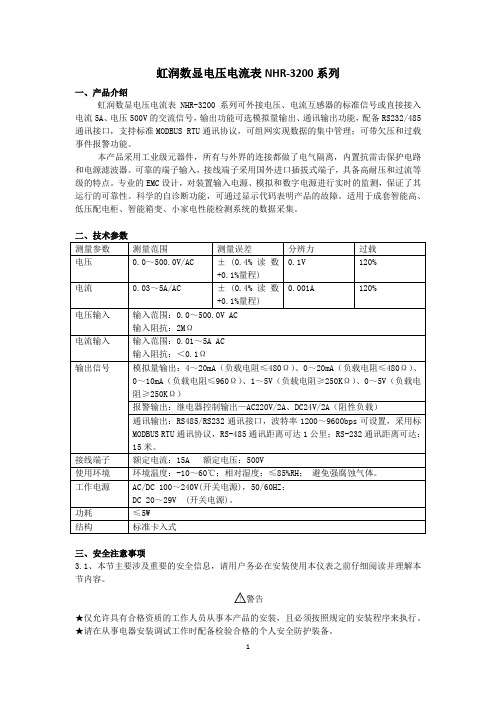
虹润数显电压电流表说明书

虹润数显电压电流表NHR-3200系列一、产品介绍虹润数显电压电流表NHR-3200系列可外接电压、电流互感器的标准信号或直接接入电流5A、电压500V的交流信号,输出功能可选模拟量输出、通讯输出功能,配备RS232/485通讯接口,支持标准MODBUS RTU通讯协议,可组网实现数据的集中管理;可带欠压和过载事件报警功能。
本产品采用工业级元器件,所有与外界的连接都做了电气隔离,内置抗雷击保护电路和电源滤波器。
可靠的端子输入,接线端子采用国外进口插拔式端子,具备高耐压和过流等级的特点。
专业的EMC设计,对装置输入电源、模拟和数字电源进行实时的监测,保证了其运行的可靠性。
科学的自诊断功能,可通过显示代码表明产品的故障。
适用于成套智能高、低压配电柜、智能箱变、小家电性能检测系统的数据采集。
二、技术参数三、安全注意事项3.1、本节主要涉及重要的安全信息,请用户务必在安装使用本仪表之前仔细阅读并理解本节内容。
警告★仅允许具有合格资质的工作人员从事本产品的安装,且必须按照规定的安装程序来执行。
★请在从事电器安装调试工作时配备检验合格的个人安全防护装备。
★不允许单独操作。
★请在进行安装操作之前关闭所有电源。
★请在检查、测试、维护本仪表之前断掉所有电源。
请关注电源系统的设计细节,包括可能有的后备电源。
★请注意不要将工作区域内的工具或者其它物体遗留在本仪表内。
★成功地安装本仪表依靠于正确的安装、操作和使用规范。
忽视基本的安装要求可能会导致人身伤害以及电子仪表或其它财产的损害。
★请在使用高阻表测试已经安装好的仪表之前,断开所有的与之相连的输入和输出连线。
★请注意高压测试有可能会导致仪表内的元件损坏。
3.2、安装使用流程1)、请参照装箱清单检查确认由到的仪表是否完整。
如有存在遗漏请及时通知供货商或本公司。
2)、使用前请确认被测试参数的范围满足仪表的测试参数的量程范围,严禁进行超出量程的参数测试。
3)、使用前请确认能够提供满足仪表工作要求的工作电源。
PanelView 5310 终端 用户手册说明书

目录
概述 安装 PanelView 5310 终端
配置终端设置
前言
变更摘要. . . . . . . . . . . . . . . . . . . . . . . . . . . . . . . . . . . . . . . . . . . . . . . . . 7 包装清单. . . . . . . . . . . . . . . . . . . . . . . . . . . . . . . . . . . . . . . . . . . . . . . . . 7 索取开源软件包的对应源代码 . . . . . . . . . . . . . . . . . . . . . . . . . . . . . . 8 产品固件和发行说明 . . . . . . . . . . . . . . . . . . . . . . . . . . . . . . . . . . . . . . 8 其他资源. . . . . . . . . . . . . . . . . . . . . . . . . . . . . . . . . . . . . . . . . . . . . . . . . 9
第1章
关于 PanelView 5310 终端 . . . . . . . . . . . . . . . . . . . . . . . . . . . . . . . . 11 硬件特性. . . . . . . . . . . . . . . . . . . . . . . . . . . . . . . . . . . . . . . . . . . . . . . . 12 操作员控制. . . . . . . . . . . . . . . . . . . . . . . . . . . . . . . . . . . . . . . . . . . . . . 13 触摸手势. . . . . . . . . . . . . . . . . . . . . . . . . . . . . . . . . . . . . . . . . . . . . . . . 13 Studio 5000 环境 . . . . . . . . . . . . . . . . . . . . . . . . . . . . . . . . . . . . . . . . 14 EtherNet/IP 通信 . . . . . . . . . . . . . . . . . . . . . . . . . . . . . . . . . . . . . . . . 15 典型配置. . . . . . . . . . . . . . . . . . . . . . . . . . . . . . . . . . . . . . . . . . . . . . . . 15 产品目录号说明 . . . . . . . . . . . . . . . . . . . . . . . . . . . . . . . . . . . . . . . . . 15 产品选择. . . . . . . . . . . . . . . . . . . . . . . . . . . . . . . . . . . . . . . . . . . . . . . . 16 附件. . . . . . . . . . . . . . . . . . . . . . . . . . . . . . . . . . . . . . . . . . . . . . . . . . . . 16 以太网电缆. . . . . . . . . . . . . . . . . . . . . . . . . . . . . . . . . . . . . . . . . . . . . . 17
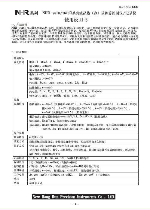
虹润NHR液晶热量积算控制仪说明书

外型尺寸 开孔尺寸尺寸类型宽1608096高8016096深1101101103、仪表的安装(1)在表盘上安装仪表的方法按照不同仪表所需的开孔尺寸在盘面上开好对应尺寸的安装孔,将密封圈套在仪表上,再将仪表嵌入到开好内容选择菜单时,用于确认菜单中的选择项修改参数时,用于确认新设定的参数值画面显示时,配合“▲”键可进组态菜单页显示历史数据时,用于确认下一步要修改的追忆时间配合“ ”键可对累积量、掉电累积时间清零设定参数时,配合“ ”键用于移动小数点的位置选择菜单时,用于光标下移修改参数时,用于减少光标指定处的数值测量显示时,用于同一通道显示画面的翻页修改追忆时间时,用于减少光标指定处的时间值选择菜单时,用于光标上移修改参数时,用于增加光标指定处的数值修改追忆时间时,用于增加光标指定处的时间值选择菜单时,用于光标左移设定参数时,用于光标左移修改追忆时间时,用光标左移显示历史数据时,用于从当前时间向后搜索追忆时段向前搜索追忆时段过程中,用于停止搜索选择菜单时,用于光标右移设定参数时,用于光标右移修改追忆时间时,用光标右移追忆历史数据时,用于从当前时间向前搜索追忆时段测量显示时,用于不同通道之间显示画面的切换设定结束时,用于进入测量显示画面在实时曲线画面或历史曲线画面下,可修改曲线画面的时标确认键光标下移键光标上移键光标左移键光标右移键F2F1在确定仪表接线无误时,方可上电。
开机时,系统将会用几秒或几分钟左右的时间进行系统初始化,请耐心七、仪表参数说明:1)“通道”参数——计算带温压补偿的流量时,输入通道01为流量(差压)信号;02为入温信号;03为出温信号。
名称输入通道输入类型输入单位滤波系数量程下限量程上限棒图下限棒图上限信号切除累积功能输入通道输入类型输入单位滤波系数量程下限量程上限棒图下限棒图上限信号切除累积功能输入通道输入类型输入单位滤波系数量程下限量程上限棒图下限棒图上限信号切除累积功能输入通道输入类型输入单位滤波系数量程下限量程上限棒图下限棒图上限信号切除累积功能设定范围01见输入类型表见工程单位表0~19-9999~99999字-9999~99999字-9999~99999字-9999~99999字-25.0~100.0ON:累积02见输入类型表见工程单位表0~19-9999~99999字-9999~99999字-9999~99999字-9999~99999字-25.0~100.0ON:累积OFF:无累积03见输入类型表见工程单位表0~19-9999~99999字-9999~99999字-9999~99999字-9999~99999字-25.0~100.0ON:累积OFF:无累积04见输入类型表见工程单位表0~19-9999~99999字-9999~99999字-9999~99999字-9999~99999字-25.0~100.0ON:累积OFF:无累积说明第一输入通道的通道号(不可修改)输入信号类型(见输入信号类型表)显示值的工程单位(见注1)单位秒量程下限值(小数点设置见注2)量程上限值(小数点设置见注2)显示下限值显示上限值小信号切除百分比值(见注3)流量信号的累积功能第二输入通道的通道号(不可修改)输入信号类型(见输入信号类型表)显示值的工程单位(见注1)单位秒量程下限值(小数点设置见注2)量程上限值(小数点设置见注2)显示下限值显示上限值小信号切除百分比值(见注3)设定通道是否为流量信号,如果是流量信号,就开通累积功能,该参数设置为ON,否则关闭,设置为OFF。
NHR-A31系列电压输入检测端隔离栅产品说明书

789 1011124 认证参数3 技术参数CNEx16.4024【Exia Ga】IIC(国家级仪器仪表防爆安全监督检验站认证)7-8、10-11Um=250VAC/DC Uo=13.65VDC Io=9mA Po=31mW Co=0.56μF Lo=100mH证书号防爆标志认证参数端子最大允许电压电压电流功率电容电感DC24V±10%RS485输出:≤0.7W;模拟量输出:≤1.4W(单路),≤1.8W(双路);开关量输出:≤1.4W 0~5V,1~5V,0~5V开方,1~5开方(订货时确定或配置编程自行编程)≥510KΩ模拟量输出,RS485信号输出,开关量输出电流输出时:RL≤500Ω;电压输出时:RL≥250KΩ传输延时≤10μs,信号传输率≤9.6kbps继电器输出驱动能力:125VAC/0.6A,30VDC/2A 继电器响应时间:<5ms晶体管集电极输出:高电平VCC(≤30V),低电平≤2.5V 0.2%FS 2500Vrms (1 min,无火花)0~50℃(无凝露、无结冰)25%~85%RH-10~60℃(无凝露、无结冰)符合GB/T18268工业设备应用要求(IEC 61326-1)电源额定工作电压范围功耗危险侧输入信号类型输入阻抗安全侧输出信号类型输出负载特性RS485信号输出开关量输出传输精度绝缘强度本安端与非本安端环境条件工作温度相对湿度保存温度标准电磁兼容性5 匹配原则为保证设备的安全正常使用,本安全回路系统各配置间必须满足以下条件:本安电气设备的防爆标志级别不能高于回路数字显示仪的防爆标志级别:关联设备、本安电气设备与连接电缆认证参数之间要符合以下不等式:回路数字显示仪Uo Io Po Co Lo安全参数匹配条件≤≤≤≥≥本安仪表参数+电缆参数Ui Ii Pi Ci+Cc Li+LcIn2 V In2 VIn2 V中国国家强制性产品认证。
NHR1303系列经济型三位显示模糊PID温控器使用说明书

的参数不显示):
参数
AT
HSV P I D T
符号 LoC
AL1 AL2 AT
AH1 AH2 HSV
P I
D
T
名称 设定参数禁锁
第一报警值 第二报警值 自整定参数
第一报警回差 第二报警回差 控制输出回差值
比例 积分时间
微分时间
PID 调节运算周期
设定范围(字) LoC=00 LoC≠00.132 LoC=132
出厂预定值 2 0
2
1
1 0 1.00
分度号 Pn 信号类型 测量范围 分度号 Pn 信号类型
测量范围
0
热电偶 B 400~999℃
5
1
热电偶 S 0~999℃
6
热电偶 J 热电偶 R
0~999℃ 0~999℃
2
热电偶 K 0~999℃
7
热电偶 N
0~999℃
3
热电偶 E 0~999℃
11
热电阻 Cu50 -50~150℃
出厂预定值 00
5.0 0
0.0 0.0 0.0 500 400
100
8
4.2 控制目标值 SV 的设置
在实时测量状态下,按压 键 5 秒后,即进入控制目标值 SV 的设定状态,
按增减键进行设置,目标值设置完成后按 键退到实时测量状态。(注:控制方
式选择定值控制才有效)
参数 符号 名称 设定范围
4
热电偶 T 0~400℃
14
热电阻 Pt100 -199~650℃
注 1:当仪表信号断线时,PID 停止输出。 4.4 系统 PID 参数和自整定
系统调试时,可利用自整定功能,方便地找到系统最佳的 PID 参数,提高调
NHR-5100系列单回路测量显示控制仪

版本号:5100-160112NHR-5100系列单回路数字显示控制仪使用说明书一、产品介绍NHR-5100系列单回路数字显示控制仪采用全自动贴片封装工艺,具有很强的抗干扰能力。
设计了双屏LED数码显示,显示内容更丰富。
可与各类传感器、变送器配合使用,实现对温度、压力、液位、速度、力等物理量的测量显示,输出功能包括:报警控制、模拟变送、RS485/232通讯等等,比传统的数显仪表还新增加了还原出厂默认参数,操作更简便,适用更广泛。
二、技术参数输入输入信号电流电压电阻电偶输入阻抗≤250Ω≥500KΩ输入电流最大限制≤30mA输入电压最大限制≤6V输出输出信号电流电压继电器24V配电或馈电输出负载能力≤500Ω≥250 KΩ(注:需要更高负载能力时须更换模块)AC220V/0.6(小)DC24V/0.6A(小)AC220V/3A(大)DC24V/3A(大)见备注≤30mA综合参数测量精度0.2%FS±1字设定方式面板轻触式按键数字设定;参数设定值密码锁定;设定值断电永久保存。
显示方式-1999~9999测量值显示,0~100%测量值光柱显示,发光二级管工作状态显示使用环境环境温度:0~50℃;相对湿度:≤85%RH;避免强腐蚀气体工作电源AC 100~240V(开关电源),(50-60HZ);DC 20~29V (开关电源)功耗≤5W结构标准卡入式通讯采用标准MODBUS通讯协议,RS-485通讯距离可达1公里,RS-232通讯距离可达15米。
注:仪表带通讯功能时,通讯转换器最好选用有源转换器备注:外形尺寸为D、E、H的仪表继电器输出时允许负载能力为AC220V/0.6A,DC24V/0.6A。
三、仪表的显示面板和功能键1)仪表外形尺寸及开孔尺寸:外形尺寸开孔尺寸160*80mm(横式/光柱)152*76mm80*160mm(竖式/光柱)76*152mm96*96mm(方式/光柱)92*92mm96*48mm(横式)92*45mm48*96mm(竖式)45*92mm72*72mm(方式)68*68mm48*48mm(方式)45*45mm2)数码管PV显示窗:显示测量值;在参数设定状态下,显示参数符号SV显示窗:显示输入分度号、报警值等,可根据要求自行选择显示;在参数设定状态下,显示设定参数值。
- 1、下载文档前请自行甄别文档内容的完整性,平台不提供额外的编辑、内容补充、找答案等附加服务。
- 2、"仅部分预览"的文档,不可在线预览部分如存在完整性等问题,可反馈申请退款(可完整预览的文档不适用该条件!)。
- 3、如文档侵犯您的权益,请联系客服反馈,我们会尽快为您处理(人工客服工作时间:9:00-18:30)。
nhr5310c数显表说明书
香港虹润 NHR-5310C-14/X-0/X/2/X/X-A PID调节器
产品描述
NHR-5300系列人工智能PID调节器采用微分先行的控制算法,带有外给定和阀位控制功能。
可与各类传感器、变送器配合使用,实现对温度、压力、液位、容量、速度等物理量的测量显示,并配合各种执行器对电加热设备和电磁、电动阀进行PID调节和控制、报警控制、数据采集等功能。
产品特点
1.双屏LED数码显示,且带有光柱模拟指示功能(0~百分bai)。
2.具备36种号输入功能,可任意选择输入号类型;0.2%级测量精度。
3.具备“上下限报警”、“偏差报警”、“LBA报警”、“闪烁报警”等报警功能,带LED报警灯指示。
4.可带一路PID控制输出和一路模拟量变送输出,具有电流、电压、SSR驱动、单/三相可控硅过零触发、继电器接点等输出控制方式可选择。
5.带PID参数自整定功能,控制输出手动/自动无扰切换功能,控制准确且无超调。
6.支持RS42串行接口,采用标准MODBUS RTU通讯协议。
7.仪表可带RS232C打印功能,具有手动打印、定时打印、
报警打印等功能。
.带DC24V馈电输出,为现场变送器配电。
9.输入、输出、电源、通讯相互之间采用光电隔离技术。
10.具备多种外形尺寸及样式供用户选择。
11.参数设定密码锁定、参数设置断电永9保存,具备参数
恢复出厂设定功能。
接线图
仪表选型
NHR-5310□-□/-□/□/□/□/□( )-□-( )
单路控制①②③④⑤⑥⑦⑧⑨⑩
NHR-5320□-□/□-□/□/□/□/□( )-□-( )
外给定控制①②③④⑤⑥⑦⑧⑨⑩
NHR-0□-□/□-□/□/□/□/□( )-□-( )
阀位控制①②③④⑤⑥⑦⑧⑨⑩M 160*0*110mm(横式)
0*160*110mm(竖式)
96*96*110mm(方式)
96*4*110mm(横式)
4*96*110mm(竖式)
72*72*110mm(方式)
4*4*110mm(方式)
160*0*110mm(横式/光柱)
0*160*110mm(竖式/光柱)
96*96*110mm(方式/光柱) X
00
01
02
04
05
06
07 0
09
10
11
12
13
14
15
16
17 1
20
21
22
23
24
25
26
27 2
29
30
31
32
33
34
55
56 无输入号
热电偶B(400~100℃)
热电偶S(0~1600℃)
热电偶K(0~1300℃)
热电偶E分度(0~1000℃)
热电偶T分度(-200.0~400.0℃) 热电偶J分度(0~1200℃)
热电偶R分度(0~1600℃)
热电偶N分度(0~1300℃)
热电偶F2分度(700~2000℃)
热电偶Wre3-25分度(0~2300℃) 热电偶Wre5-26分度(0~2300℃) 热电阻Cu50(-50.0~150.0℃)
热电阻Cu53(-50.0~150.0℃)
热电阻Cu100(-50.0~150.0℃)
热电阻Pt100(-200.0~650.0℃) 热电阻BA1(-200.0.0~600.0℃) 热电阻BA2(-200.0~600.0℃)线性电阻0~400Ω(-1999~9999) 远传电阻0-350Ω (-1999~9999) 远传电阻30-350Ω (-1999~9999) 0~20mV (-1999~9999)
0~40mV (-1999~9999)
0~100mV (-1999~9999)
-20~20mV (-1999~9999)
-100~100mV (-1999~9999)
0~20mA (-1999~9999)
0~10mA (-1999~9999)
4~20mA (-1999~9999)
0~5V (-1999~9999)
1~5V (-1999~9999)
-5~5V (-1999~9999)
0~10V (-1999~9999)(不可切换)
0~10mA开方 (-1999~9999)
4~20mA开方 (-1999~9999)
0~5V开方 (-1999~9999)
1~5V开方 (-1999~9999)
全切换
特殊规格④控制输出(OUT1)代码输出类型(负载电阻RL) 0
K1
K3
K4
K5
K6
4-20mA(RL≤600Ω)
1-5V(RL≥250KΩ)
0-10mA(RL≤1.2KΩ)
0-5V(RL≥250KΩ)
0-20mA(RL≤600Ω)
0-10V(RL≥4KΩ)
继电器接点输出
单相可控硅过零触发脉冲输出
固态继电器驱动电压输出
双向可控硅通断输出
三相可控硅过零触发脉冲输出
特殊规格⑤变送输出(OUT2)代码输出类型(负载电阻RL) X
无输出
4-20mA(RL≤600Ω)
1-5V(RL≥250KΩ)
0-10mA(RL≤1.2KΩ)
0-5V(RL≥250KΩ)
0-20mA(RL≤600Ω)
0-10V(RL≥4KΩ)
特殊规格⑥报警输出(继电器接点输出)代码报警限数X
4 无输出
1限报警
2限报警
3限报警
4限报警⑦通讯输出/外部事件接入⑧馈电输出代码通讯接口/数字量输入接口代码馈电输出(输出电压) X
D1
D2
D3
Y1
Y2
Y3 无输出
RS-45通迅接口(Modbus)RS232通迅接口(Modbus)RS232C打印接口
外部事件输入1(强制手动)外部事件输入2
外部事件输入3 X
1P
2P 无输出
1路馈电输出
2路馈电输出
如“2P(12/24)”表示$路12V,第二路24V馈电输出。
⑨供电电源⑩备注(无可省略)代码电压范围 A:AC/DC 100-240V(50/60Hz)
D:DC 20-29V。
