克兰茨固定旋流风口样本
旋流风口

一、产品选用要点
1.旋流风口选用主要控制参数风口型式、材质、规格、出口风速、全压损失和气流射程等。
2.旋流风口的材质主要有钢制和铝合金两类。
3.旋流风口的型式、特征及适用范围见表1。
表1 旋流风口型式、特征及适用范围
4.选型要点
1)根据工程特点、所需气流组织类型、调节性能和送风方式等,选择相应的风口类型。
2)根据需要风量[送风或排(回)风],在风口颈部(或风口进出口断面处)允许的风速
范围内,确定所需风口的尺寸。
3)校核所选择风口的主要技术性能,如射程、压力损失、噪声指标以及工作区域内的风
速与温差。
4)确定所选风口的布置安装方式以及与风道的连接方式。
二、施工、安装要点
1.安装前应检查风口机械性能。
a)风口的活动零件,要求动作自如、阻尼均匀,无卡死和松动。
b)导流片可调或可拆卸的产品,要求调节拆卸方便、可靠,定位后无松动现象。
2.风口外表装饰面应平整、叶片分布应匀称、颜色应一致、无明显的划伤和压痕。
3.风口允许偏差值应符合表2规定。
表2 风口尺寸允许偏差单位:mm
三、执行标准
产品标准
JG/T14-1999《通风空调风口》
JG/T20-1999《空气分布器性能试验方法》
工程标准
GB50243-2002《通风与空调工程施工质量验收规范》。
外来图样审核记录

√
√
√
焊接专业标准
JB/T4709、HG20583
√
√
无损检测标准
JB/T4730.2-2005-AB级,AB焊缝管程RT-20%-Ⅲ
壳程RT-100%-Ⅱ,CD焊缝壳程MT-100%-Ⅰ
√
√
√
容器类别
Ⅱ类
√
工作压力(Mpa)
管程:0.4壳程:0.7
√
设计压力(Mpa)
管程:0.44壳程:0.77
√
工作温度(℃)
管程:32-37壳程:177-50
√
设计温度(℃)
管程:40壳程:180
√
介质
壳程:C4气体介质特性:易燃易爆管程:循环水
√
主要受压件材料牌号及标准
筒体GB713-2008-Q345RGB13296-2007-0Cr17Ni14Mo2
√
√
腐蚀余量(mm)
管程:0壳程:2
√
焊接接头系数
压力容器外来图样审核记录MR3.3-13 NO.
产品名称
吸附塔冷凝器
图号
SB25-83-1
制造编号
R11062
审核内
焊接
检验
设计单位
河北凯米克化工医药工程设计有限公司
√
设计资质
TS1213044-2011
√
设计签署
标准化、设计、校核、审核、工艺
√
设计标准
TSGR0004-2009、GB151-1999、JB/T4711-2003
√
泄露试验要求(MPa)
壳程:0.77
√
预防腐蚀要求
碳钢部分环氧富锌底漆两遍,环氧面漆两遍
√
安全附件要求
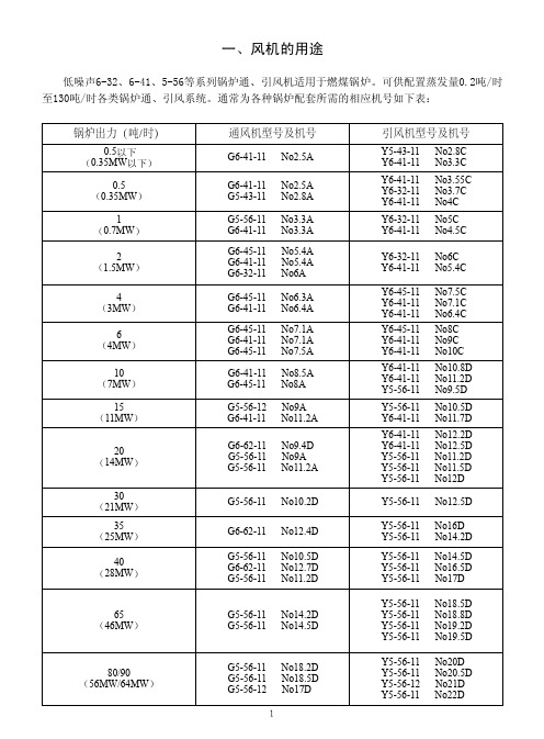
G Y6-41 6-32 5-56风机样本
5
5、在与性能表相同进气条件下风机流量、全压、转速、功率变换关系式:
n0 Q0 ==
n1 Q1
P0 = 3 N0
P1
Байду номын сангаас
N1
式中:n0——为性能表中额定转数 从上述关系和第二款内所列各项公式中告诫我们:在未加大电机容量的情况下,不得将引
风机(设计工作温度t0=200℃)在冷态中运行;不得随意提高风机转速。否则电机将过载甚至烧 毁。
Y6-41-11 Y6-41-11 Y5-56-11 Y5-56-11 Y5-56-11
No7.5C No7.1C No6.4C
No8C No9C No10C
No10.8D No11.2D No9.5D
No10.5D No11.7D
No12.2D No12.5D No11.2D No11.5D No12D
G5-56-11 No14.2D G5-56-11 No14.5D
G5-56-11 G5-56-11 G5-56-12
No18.2D No18.5D No17D
1
引风机型号及机号
Y5-43-11 No2.8C Y6-41-11 No3.3C
Y6-41-11 Y6-32-11 Y6-41-11
No3.55C No3.7C No4C
3
2、机壳:用普通钢板焊成蜗形壳体,与支座呈分装或焊接一体两种结构,稳固可靠。 3、进风口:制成收敛式流线形的整体结构,用螺栓固定在风机入口侧。叶轮、机壳、进风 口部可选用不锈钢或防腐涂层。 4、传动组:由主轴、整体轴承箱、滚动轴承、皮带轮或联轴器等组成。用46号机油润滑, 密封性能好,运转平稳,寿命长。(注:当采用油脂润滑时,可用锂基脂润滑) 5、整体支架结构的风机产品: 该结构风机产品如图所示:它是用型钢结构的焊接支架将A式、C式、D式等传动形式的离心 风机组合在同一刚性支架上,支架底平面上装配有承载能力和固有振动频率相适应的减震器。该 种结构产品可以直接放在具有足够承载能力和足够大质量的平整混凝土地平面上即可。 我公司推出该种结构产品以来,因它鲜明的优势、优点,已被诸多用户和设计院采用、销量 猛增! 该产品的优点有: 一、无论A式、C式、D式传动,该结构产品将风机组装的关键部位(如叶轮与风机进口的轴 向、径向搭接间隙;叶轮与主轴装配;联轴器装配;皮带轮装配等)交与厂家来完成。这对确保 风机性能及运行质量是至关重要的。 二、省去了各式传动的混凝土基础、省去了各种传动形式地脚螺栓的定位和二次浇灌与养 护。不但节约资金,更节约了安装时间。 三、节省了现场安装、调整的人力、设备和时间。 四、当系统需要调整、改造或拆除时,可以很方便的拆除更换。整体吊走调离即可。 事物总是一分为二;优点尽显的同时也有缺点: 一、该结构产品总体尺寸及重量都比较大、尤其是大机号、大功率的风机产品,往往超高、 超宽、超重、给运输、现场安装均带来不便。因此在订货及现场施工组织时必须给予充分的重 视,让产品从生产地能顺利进入运行现场,这是用户必须计划考虑的课题。 二、产品出厂,经运输、吊装各个环节难免磕碰,造成损伤漆面、甚至松脱、错位。因此现 场就位后,必须认真检查、恢复原有的组装尺寸精度。 三、以钢架替代混凝土基础困此该产品造价比散件裸机要高。必须给予综合的对比。对比混 凝土基础造价、对比安装调试的人、机投入、对比耗用工期时间…… 四、由于该结构产品是位于减震器的软支撑上运行的,故它比刚性支撑的振幅(振动速度) 要大,特别是叶轮的动平衡被破坏后更为明显。因此该产品在风机进出口管道的软连接上,必须 有良好的设计。选用优质的软联接产品,弥补接口错位,防止振动传递。为防止振动造成风机移 位,对四角的减震器也应作防位移的结构处理。 我公司整体支架结构风机的特点: 一、为确保风机运行时支架有足够的刚度。在支架尺寸设计及用料上,充分考虑承载运行的 反力,确保长期安全可靠运行。考虑便于维护、修理,使整体支架结构合理,注入人性化的因 素。 二、各类板材均采用等离子切割下料。注重焊接工艺防止变形。确保尺寸准确、平整、美 观。 整体支架结构风机产品订货须知: 一、凡我公司生产的各类风机均可订购整体支架产品。 二、鉴于该类产品因系列、机号、旋向、角度的差异,均会造成产品尺寸结构各异,故难以
妥思旋流风口
概述-------------------------------------- 2 型号·尺寸-------------------------------- 3 材料-------------------------------------- 3 安装-------------------------------------- 4 符号定义---------------------------------- 5
规格 最大射程H1max(单位m)
规格 最大射程H1max(单位m)
风量V(单位I/s)
6 送风角 6 0 °时的最大射程
风量V(单位I/s)
8 垂直送风时的最大射程
规格 最大射程H1max(单位m)
风量V(单位I/s)
V· [m3/h] = V· [I/s]×3.6
315
400
630
800
412
515
810
1015
符号定义,噪声频谱参数
符号定义
V (单位I/s或者m3/h): 每个风口的送风量
A,B
(单位m): 两个风口之间的距离
X
(单位m): 风口中央到墙的距离
H1
(单位m): 风口面板到停留区的距离
vH1 (单位m/s): 在H1距离处两个风口之间的平均风速
800
3 2 0 -2 -4 -11 -18 -26 10 3 1 -2 -5 -11 -17 -21 7 2 1 -2 -5 -10 -16 -22
315
1 -1 -2 -5 -6 -7 -8 -17 3 1 -3 -4 -5 -7 -10 -18 1 -1 -2 -4 -5 -7 -10 -18
690
卡鲁塞尔氧化沟2000工艺流程

卡鲁塞尔氧化沟2000工艺流程下载温馨提示:该文档是我店铺精心编制而成,希望大家下载以后,能够帮助大家解决实际的问题。
文档下载后可定制随意修改,请根据实际需要进行相应的调整和使用,谢谢!并且,本店铺为大家提供各种各样类型的实用资料,如教育随笔、日记赏析、句子摘抄、古诗大全、经典美文、话题作文、工作总结、词语解析、文案摘录、其他资料等等,如想了解不同资料格式和写法,敬请关注!Download tips: This document is carefully compiled by theeditor.I hope that after you download them,they can help yousolve practical problems. The document can be customized andmodified after downloading,please adjust and use it according toactual needs, thank you!In addition, our shop provides you with various types ofpractical materials,such as educational essays, diaryappreciation,sentence excerpts,ancient poems,classic articles,topic composition,work summary,word parsing,copy excerpts,other materials and so on,want to know different data formats andwriting methods,please pay attention!深入解析:卡鲁塞尔氧化沟2000工艺流程卡鲁塞尔氧化沟2000是一种先进的污水处理技术,以其高效、节能和环保的特性在全球范围内广泛应用。
MASCOT产品选型样本

201 支架 202 气缸 210 调节螺钉 211 执行机构推杆 213 行程刻度牌 225 活塞 227 弹簧扣 228 执行机构推杆垫片 229 弹簧 248 调节螺钉垫片 249 阀杆夹 253 支架衬套 256 固定环 271 活塞O形环 272 活塞推杆O形环 274 支架O形环 275 执行机构推杆O形环 348 执行机构推杆锁紧螺母
锻造
锻造车间的能力包括落锤锻造和自由锻造直径最大至1000mm的各种标准材料 和特殊材料,制造成阀盖、法兰、阀塞和阀座环。
配合
诸如大型加工中心和数控机床(CNC)等扩展 设备能够生产各种不同尺寸的阀组件。
涂装
可以满足各种不同的涂装要求,比如标准涂装、用于海上服务的厚涂层涂装,以及用 于高温场合的涂装要求。
MASCOT Industrial 15A Randor Street Campbellfield, Victoria 3061 Australia
Tel: +61 3 9357 6555 | Fax: +61 3 9357 6566 Email: sales@ | Web: 本手册仅供信息参考,我们会努力确保资料的准确性和所提供技术规格的精确度, 但手册内容不作为对 于产品本身的解释或担保。MASCOT Industrial保留对产品设计的更改或改进的权力,本手册中产品信息 和技术规格如有变更,恕不另行通知。MASCOT Industrial对产品的选型,使用和维护不予负责。产品的
高端技术 紧密关断
澳大利亚的制造能力
高可靠性 值得信赖
Page 2
源自澳大利亚的制造能力
MASCOT公司所具有的源自澳大利亚的制造能力包括针对困难工况,应用多种 材料和特殊设计,制造压力等级为ASME CL150至CL4500,尺寸范围由0.5” 至36”的球阀以及2.0”至48”的旋转阀(蝶阀、V形球阀、偏心旋塞阀)。 澳大利亚企业利用供应商合作关系来完成铸件的生产和阀组件的加工 这使加工车间的工作量更具弹性并且大大减少了生产交付周期。 与合作伙伴迄今二十年的合作使MASCOT公司在高品质和及时交付表现上取得 了有证明的良好记录。
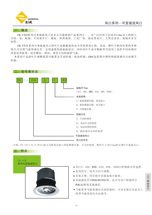
FK-YXII系列可变旋流风口
315
10 2 2 -1 -5 -18 -28 -37 10 6 2 -1 -6 -17 -28 -30 8 4 2 0 -6 -16 -28 -36
YXⅡ 旋流风口
01
风口系列—可变旋流风口
四、布置图
B
H 1.7m
min 300mm
H1
符号说明 Q-每个风口的风量。单位:m3/h A、B-两个风口之间的距离。单位:m X-风口中心到墙的距离。一般可取0.8
~1.2倍的A或B值。单位:m
H1-出风口平面到停留区的距离。
A
单位:m
X
B
X
△t-送风温度与室内温度之温差。
YXⅡ 旋流风口
05
风口系列—可变旋流风口
06
LX
YXⅡ 旋流风口
风口系列—可变旋流风口
07
YXⅡ 旋流风口
风口系列—可变旋流风口
08
YXⅡ 旋流风口
风口系列—可变旋流风口
旋 流 风 口 产 品 流 通 净 面 积( m2 )
表三
规格 AXY
315 0.0338
400 0.055
500 0.086
54
118
56
94
52
4500
132
58
46
60
119
56
5000
168
62
181
64
147
60
1500
9
21
11
22
7.6
20
2000
15
29
17
30
13
28
2500
24
34
27
35
VQC4000-TFP53 阀门操纵控制阀门手册说明书

Solenoid valve for actuator control: VQC4101R-5-X17 / VQC4301R-5-X17 VQC4401R-5-X17 / VQC4501R-5-X17(Basic and well-tried safety principles in accordance to ISO 13849)The intended use of the valve is to control the movement of an actuator.This product is validated according to ISO 13849 basic and well-tried safety principles. Refer to Doc. Nr. VQC4000-SMP0001.This manual contains essential information for the protection of users and others from possible injury and/or equipment damage.∙ Read this manual before using the product, to ensure correct handling, and read the manuals of related apparatus before use. ∙ Keep this manual in a safe place for future reference.∙ These instructions indicate the level of potential hazard by label of “DANGER”, “WARNING” or “CAUTION”, followed by important safety information which must be carefully followed.∙ To ensure safety of personnel and equipment the instructions in this manual and the product catalogue must be observed, along with other relevant safety practices.Take care about the compliance with the relevant safety laws and standards.Warning∙∙The compatibility of pneumatic equipment is the responsibility of the person who designs the pneumatic system or decides its specifications. Since the products specified here can be used in various operating conditions, their compatibility with the specific pneumatic system must be based on specifications or after analysis and/or tests to meet specific requirements.∙Only trained personnel should operate pneumatically operated machinery and equipment.Compressed air can be dangerous if an operator is unfamiliar with it. Assembly, handling or repair of pneumatic systems should be performed by trained and experienced personnel.∙Do not service machinery/equipment or attempt to remove components until safety is confirmed.1) Inspection and maintenance of machinery/equipment should only be performed after confirmation of safe locked-out control positions.2) When equipment is to be removed, confirm the safety process as mentioned above. Switch off air and electrical supplies and exhaust all residual compressed air in the system.3) Before machinery/equipment is re-started, ensure all safety measures to preventsudden movement of cylinders etc. (Supply air into the system gradually to create back pressure, i.e. incorporate a soft-start valve).∙Do not use this product outside of the specifications. Contact SMC if it is to be used in any of the following conditions:1) Conditions and environments beyond the given specifications, or if the product is to be used outdoors.2) Installations in conjunction with atomic energy, railway, air navigation, vehicles, medical equipment, food and beverage, recreation equipment, emergency stop circuits, press applications, or safety equipment.3) An application which has the possibility of having negative effects on people, property, or animals, requiring special safety analysis. ∙Effect of back pressure when using a manifoldThis valve is designed to be used on a manifold. This valve may experience back pressure due to pressure in the manifold exhaust ports. Back pressure check valves can be used to prevent back pressure affecting the outlet ports of this valve. ∙VentilationProvide ventilation when using a valve in a confined area, such as in a closed control panel. For example, install a ventilation opening, etc. in order to prevent pressure from increasing inside of the confined area and to release the heat generated by the valve. ∙Operation in a low temperature conditionIt is possible to operate a valve in extreme temperature, as low as –moisture etc. in low temperature.∙Do not disassemble the product or make any modificationsCaution∙ Ensure that the air supply system is filtered to 5 μm.2 SpecificationsNote 1)When the external pilot pressure is removed the main valve returns to the original position. The valves are to be used with a suitable manifold with external pilot supply or VQC4101-5-X10.Note 2)Values represented in this column are based on JIS 8375-1981 (operating with clean air and a supply pressure of 0,5 MPa equipped with light/surge voltage suppressor. Values vary depending on the pressure as well as the air quality.) Tested with ports size C8 and without back pressure check valves Note 3)Impact resistance: No malfunction occurred when it was tested with a drop tester in the axial direction and at right angles to the main valve & armature; in both energized & de-energised states and for every time in each condition (Values at the initial period.)Vibration resistance: No malfunction occurred in a one-sweep test between 45 and 2000 Hz. Tests are performed at both energized and de-energized states in the axial direction and at right angles to the main valve & armature. Note 4) If power supply is under -10% of standard power supply 24 V DC the valve may switch to the OFF position. The valve may switch to the de-energized state. 2.3 Symbol 2 position single3 position closed center3 position exhaust center3 position pressure centerFigure 32.4 Light/Surge Voltage SuppressorFigure 43 InstallationWarning3.1 Environment1. Do not use in an environment where the product is directly exposed to corrosive gases, chemicals, salt water, water or steam.2. Products with IP67 enclosures (based on IEC60529) are protected against dust and water, however, these products cannot be used in water.3. Incorrect mounting of the product violates the IP67 rating. Be sure to read the precautions of mounting for each product.4. Do not use in an explosive atmosphere.5.The product should not be exposed to prolonged sunlight. Use a protective cover.6. Do not mount the product in a location where it is subject to strong vibrations and/or shock. Check the product specifications.7. Do not mount the product in a location exposed to radiant heat.3.2 Piping1. Preparation before pipingBefore piping is connected, it should be thoroughly blown out with air (flushing) or washed to remove chips, cutting oil and other debris from inside the pipe.Install piping so that it does not apply pulling, pressing, bending or other forces the valve body. 2. Holding of pressureRubber sealed spool valves may have a slight leakage. This has to be taken into account for applications, in which the loss of pressure leads to a hazardous movement. 3. Maintenance space.The installation should have sufficient space for maintenance activities (removal of valve, etc.).4. Release of residual pressure.Provide a residual pressure release function for maintenance activities (removal of valve, etc.)Caution3.3 Lubrication∙ SMC products have been lubricated for life at manufacture, and do notrequire lubrication in service.∙ If a lubricant is used in the system, use turbine oil Class 1 (no additive),ISO VG32. Once lubricant is used in the system, lubrication must be continued because the original lubricant applied during manufacturing will be washed away.Warning3.4 Mounting1. Stop operation if air leakage increases and the equipment do not operate properly .Check mounting conditions after air and power supplies are connected. Initial function and leakage tests should be performed after installation.2. Instruction manual (this document)Install only after reading and understanding the safety instructions. Keep on file so that it can be referred to when necessary.3. CoatingWarnings or specifications indicated on the product should not be erased, removed, or covered up.Caution3.5 Wiring1. Applied voltage.When electric power is connected to the solenoid valve, be careful to apply the proper voltage. Improper voltage may cause malfunction or coil damage.2. Confirm the connections.After completing the wiring, confirm that the connections are made correctly.4 Settings4.1 Manual overrideWarningSince connected equipment will operate when the manual override isactivated, confirm that conditions are safe prior to activation. The non-locking push type (tool required) is fitted.Figure 5The manual override will pressurize the pilot actuator and cause the main valve to change state.ORIGINAL INSTRUCTIONSVQC 4101VQC 4301,4401,45014.2 Solenoid Valve Removal and Mounting (VQC4000)Figure 64.2.1 Removal steps1. Loosen the screws until they turn freely.2. Remove the solenoid valve by lifting the coil side of the valve. If pushing down on the screw is difficult, you can alternately press down on the valve gently in the area near the manual override.4.2.2 Mounting steps1. Push the valve down into place.2. Tighten the clamp screws with a tightening torque of 0.8 to 1.2 N ・mCautionDust on the sealing surface of the gasket or solenoid valve can cause air leakage.Take care that the pilot pressure is able to exhaust. Do not block the Exhaust Ports.Order Number VQC4101R-5-X17 2-position singleVQC4301R-5-X17 3-position closed center VQC4401R-5-X17 3-position exhaust center VQC4501R-5-X173-position pressure centerSpecial pilot valve cover (Color: Red)( Dimensions are in Millimeter )Special pilot valve cover (Color: Red)( Dimensions are in Millimeter )Figure 77 MaintenanceWarning1. Perform maintenance procedures shown in this instruction manual. If handled improperly malfunction or damage of machinery/equipment may occur.2. Removing the productTo avoid the risk of being burned, ensure that the valve has had sufficient time to cool before performing work.1. Shut off the fluid supply and release the fluid pressure in the system.2. In the case of air pilot or air-operated type, shut off the supply air source and discharge the compressed air inside the pilot piping.3. Shut off the power supply.4. Remove the product.3. Low frequency operation.Valves should be operated at least once every 30 days to prevent malfunction. (Use caution regarding the air supply).4. Manual overrideWhen the manual override is operated, connected equipment will be actuated.5. Do not disassemble the product.5.1 Replacing One-touch fittingsCautionCylinder port fittings are available with cassette type manifolds and are easily replaced. Fittings are secured with a retaining clip that is inserted vertically from either the top or bottom of the manifold. After removing the valve, remove the clip with a flat head screwdriver to replace the fittings. To mount a fitting, insert the fitting assembly until it spots and reinsert the retaining clip to its designated position.Figure 88 Limitations of UseAny use in an EN ISO 13849 system must be within the specified limits and application condition. The user is responsible for the specification, design, implementation, validation and maintenance of the safety system (SRP/CS).WarningIf a safe output from a safety relay or PLC is used to operate this valve, ensure that any output test pulse duration is shorter than 1 ms to avoid the valve solenoid responding.Figure 96 ContactsAUSTRIA (43) 2262 62280-0 LATVIA(371) 781 77 00 BELGIUM (32) 3 355 1464 LITHUANIA(370) 5 264 8126 BULGARIA (359) 2 974 4492 NETHERLANDS (31) 20 531 8888 CZECH REP . (420) 541 424 611 NORWAY (47) 67 12 90 20 DENMARK (45) 7025 2900 POLAND (48) 22 211 9600 ESTONIA (372) 651 0370 PORTUGAL (351) 21 471 1880 FINLAND (358) 207 513513 ROMANIA (40) 21 320 5111 FRANCE (33) 1 6476 1000 SLOVAKIA (421) 2 444 56725 GERMANY (49) 6103 4020 SLOVENIA (386) 73 885 412 GREECE (30) 210 271 7265 SPAIN (34) 945 184 100 HUNGARY (36) 23 511 390 SWEDEN(46) 8 603 1200 IRELAND (353) 1 403 9000 SWITZERLAND (41) 52 396 3131 ITALY (39) 02 92711 UNITED KINGDOM (44) 1908 563888SMC Corporation www.smcworld,com (Global) (Europe) SMC Corporation, Akihabara UDX15F, 4-14-1, Sotokanda, Chiyoda-ku, Tokyo 101-0021 JAPANSpecifications are subject to change without prior notice from the manufacturer. The descriptions of products in this document may be used by other companies. © 2012 SMC Corporation All Rights Reserved.。
- 1、下载文档前请自行甄别文档内容的完整性,平台不提供额外的编辑、内容补充、找答案等附加服务。
- 2、"仅部分预览"的文档,不可在线预览部分如存在完整性等问题,可反馈申请退款(可完整预览的文档不适用该条件!)。
- 3、如文档侵犯您的权益,请联系客服反馈,我们会尽快为您处理(人工客服工作时间:9:00-18:30)。
Ceiling
Fig. 3: Radial slot outlet RL-C, size 375
Mode of operation
Fig. 4: Jet pattern of outlet installed flush with the ceiling
The radial slot outlet generates turbulent mixing air flow with highinduction radial air jets. As standard the preset bar position, i.e. discharge direction, is horizontal. Altering the bar position enables to adjust the discharge direction from horizontal to a downward incline. By closing several bar segments the discharge pattern may also be changed from full 4-way discharge to partial discharge. A key and instructions are available for subsequent bar adjustment. The radial slot outlet to be used as a return air inlet has its bars set to the vertical position as standard, but it can also be supplied with horizontal bars or without bars. Installation freely suspended from the ceiling In this case the outlet element is fitted with additional lateral slots. The additional air jets so obtained stabilize the whole supply air flow and raise the discharge flow, thus achieving large radial penetration depth into the room, even when cooling. The reduction of temperature and jet velocity is the same as for outlet installation flush with the ceiling.
v 1a
h s
Fig. 1: Sectional view of adjustable bar and possible bar positions
Size øE ø D 2) ø D1 ø D5 L1 H øA Weight mm mm mm mm mm mm mm kg
375 375 355 314 159 40 280 317 4.7
Air distribution systems
Radial slot outlet RL-C....
DS 4121 E 04.2013
Radial slot outlet RL-C
Construction design Preliminary remark
The circular-type radial slot outlet RL-C generates turbulent mixing air flow and is designed for air distribution in commercial applications. It is particularly suitable for spaces with high indoor air flow requirements and can be installed flush with the ceiling or freely suspended. The discharge direction can be adjusted by altering the position of several bars. This air outlet can also be used as a return air inlet.
3
Radial slot outlet RL-C
Adjustment of discharge direction Discharge direction and air volume flow rates
The radial slot outlet can discharge the supply air horizontally in 4, 3 or 2 directions. For 4-way discharge all bars are in the ‘h’ position. If air discharge is required only 3-way, 2-way symmetric, or 2-way asymmetric, then several slots are to be closed as shown below. The air volume flow rate is thus reduced; the related factors can be read off the following table.
h s
Fig. 7: Sectional view of adjustable bar and possible bar positions
Adjustment of discharge direction
Discharge direction 4-way Type 0 Size 750 600 470 375
1a Bottom view of size 750 øA 6 2 3 L1 40 ø D5 ø D1 A 60 A 1a ø D 2)பைடு நூலகம்øE 5 1 4 76 4 3 30 H
1b
Key for all pages 1 Faceplate 1a Adjustable bars 1b Lateral air slot 2 Circular connection box 3 Lateral spigot 1) · 4 V damper 5 Central fastening 6 Holes for outlet suspension
4
3
1
Construction design
The RL-C outlet is available in 4 sizes. It is consists of of the circular faceplate 1 with built-in bars 1a that can be adjusted individually, and of the circular connection box 2. For installation freely suspended from the ceiling, the outlet element is fitted with additional lateral air slots 1b. As standard the lateral connection spigot 3 1) is fitted with a damper 4 adjustable from the room. The outlet element can be easily taken down after removing the central fastening 5. The RL-C outlet will be suspended at appropriate holes 6 (ø 9 mm) positioned in the upper part of the connection box, e.g. with customary quick fasteners.
2
www.krantz.de
DS 4121 E
Detail of Fig. 2, section A - A Bar position for discharge direction: h horizontal v vertical s closed position
4x ø9
Fig. 2: Dimensions
Fig. 5: Jet pattern of outlet installed freely suspended from the ceiling
DS 4121 E
p. 3
04.2013
2.5 – 4.5 –12 K when cooling
2.7 – 4.5
www.krantz.de
+10 K when heating (£ 3 m) + 5 K when heating (> 3 m)
p. 2
04.2013
Radial slot outlet RL-C
Mode of operation
Installation flush with the ceiling With such installation and horizontal air discharge the highturbulence air jets slide along the ceiling. The resulting flow achieves intensive admixture of indoor air concomitant with fast reduction of temperature and jet velocity.
3-way Type 1