大众维修电路图 奥迪Q 电路图
奥迪Q7电路图-氙灯

*
WI-XML
页码,5/6
Audi Q7
Current Flow Diagram
No. 37 / 5
Onboard supply control unit, right gas discharge light control unit J344 - Right gas discharge light control unit J519 - Onboard supply control unit L14 - Right gas discharge (xenon) bulb L175 - Right day driving light bulb M3 - Right side light bulb M7 - Front right turn signal bulb N396 - Right headlight screen adjustment solenoid T2u - 2-pin connector, black, on front right turn signal T2v - 2-pin connector, black, on front right turn signal T10a - 10-pin connector, black, on onboard supply control unit T10o - 10-pin connector, black, in front right engine compartment T12b - 12-pin connector, black, on onboard supply control unit T14b - 14-pin connector, black, on right of headlight T32b - 32-pin connector, grey, on onboard supply control unit V49 - Right headlight range control motor Earth connection 19, in main wiring harness 384
奥迪Q7电路图14

Klimaanlage Komfortab Modelljahr2007Hinweise:InformationenüberRelaisplatz-und Sicherungsbelegungen MehrfachsteckverbindungenSteuergeräte und RelaisMasseverbindungenÃEinbauorte in derÜbersicht!InformationenüberFehlersuchprogrammeÃgeführte Fehlersuchews =weißsw =schwarz ro =rot br =braun gn =grün bl =blau gr =grau li =lila ge =gelb or =orangeT16d -Steckverbindung,16fach,schwarz,Stecker D,am Steuergerät für ClimatronicT17k-Steckverbindung,17fach,schwarz,hinter der Schalttafel rechts,Klimaanlage V2-Frischluftgebläse43-Massepunkt Säule A rechts untenB272-Plusverbindung (30)im Hauptleitungsstrang ✱-Relais-und Sicherungsträger Schalttafel Mitte ✱✱-Relais-und Sicherungsträger unter dem Fahrersitzws =weißsw =schwarz ro =rot br =braun gn =grün bl =blau gr =grau li =lila ge =gelb or =orangeT10f -Steckverbindung,10fach,rot,KupplungsstationE-Box WasserkastenT16c -Steckverbindung,16fach,braun,Stecker C,amSteuergerät für ClimatronicT16d -Steckverbindung,16fach,schwarz,Stecker D,am Steuergerät für Climatronic 379-Masseverbindung 14im Hauptleitungsstrang ✱-Ausgang Gebermassews =weißsw =schwarz ro =rot br =braun gn =grün bl =blau gr =grau li =lila ge =gelb or =orangeG386-Temperaturfühler für Mannanströmer vorn rechtsJ255-Steuergerät für ClimatronicT12g -Steckverbindung,12fach,Stecker A,am Steuergerät für ClimatronicT16d -Steckverbindung,16fach,schwarz,Stecker D,am Steuergerät für ClimatronicT17k-Steckverbindung,17fach,schwarz,hinter der Schalttafel rechts,KlimaanlageT20i-Steckverbindung,20fach,rot,Stecker B,am Steuergerät für Climatronic97-Masseverbindung 1im Leitungsstrang Klimaanlage✱-Ausgang Gebermassews =weißsw =schwarz ro =rot br =braun gn =grün bl =blau gr =grau li =lila ge =gelb or =orangeTemperaturklappe rechts J255-Steuergerät für ClimatronicT12g -Steckverbindung,12fach,Stecker A,am Steuergerät für ClimatronicT16c-Steckverbindung,16fach,braun,Stecker C,am Steuergerät für ClimatronicT16d -Steckverbindung,16fach,schwarz,Stecker D,am Steuergerät für ClimatronicT17k -Steckverbindung,17fach,schwarz,hinter der Schalttafel rechts,KlimaanlageT20i-Steckverbindung,20fach,rot,Stecker B,am Steuergerät für Climatronic V42-Gebläse für Temperaturfühler V107-Stellmotor der Defrostklappe V113-Stellmotor der UmluftklappeV159-Stellmotor der Temperaturklappe rechts97-Masseverbindung 1im Leitungsstrang KlimaanlageL31-Verbindung (5Volt)im Leitungsstrang Klimaanlage/ws =weißsw =schwarz ro =rot br =braun gn =grün bl =blau gr =grau li =lila ge =gelb or =orange rs =rosaT12g -Steckverbindung,12fach,Stecker A,amSteuergerät für ClimatronicT16c -Steckverbindung,16fach,braun,Stecker C,amSteuergerät für ClimatronicT17k -Steckverbindung,17fach,schwarz,hinter derSchalttafel rechts,KlimaanlageT20i -Steckverbindung,20fach,rot,Stecker B,amSteuergerät für ClimatronicV111-Stellmotor des Mittenausströmers rechts V213-Stellmotor der indirekten Belüftungsklappe 97-Masseverbindung 1im Leitungsstrang KlimaanlageL9-Verbindung 1im Leitungsstrang Klimaanlage L10-Verbindung 2im Leitungsstrang Klimaanlage L31-Verbindung (5Volt)im Leitungsstrang Klimaanlage ✱-Linkslenker ✱✱-Rechtslenker///ws =weißsw =schwarz ro =rot br =braun gn =grün bl =blau gr =grau li =lila ge =gelb or =orange rs =rosaG523-Potenziometer für Stellmotor desSeitenausströmers rechtsJ255-Steuergerät für ClimatronicT12g -Steckverbindung,12fach,Stecker A,amSteuergerät für ClimatronicT20i -Steckverbindung,20fach,rot,Stecker B,amSteuergerät für ClimatronicV109-Stellmotor der Fußraumklappe rechts V299-Stellmotor des Seitenausströmers links V300-Stellmotor des Seitenausströmers rechts 97-Masseverbindung 1im Leitungsstrang KlimaanlageL10-Verbindung 2im Leitungsstrang Klimaanlage L11-Verbindung 3im Leitungsstrang Klimaanlage L31-Verbindung (5Volt)im Leitungsstrang Klimaanlage//ws =weißsw =schwarz ro =rot br =braun gn =grün bl =blau gr =grau li =lila ge =gelb or =orangeG220-Potenziometer für Stellmotor derTemperaturklappe linksJ255-Steuergerät für ClimatronicT12g -Steckverbindung,12fach,Stecker A,amSteuergerät für ClimatronicT20i -Steckverbindung,20fach,rot,Stecker B,amSteuergerät für ClimatronicV108-Stellmotor der Fußraumklappe links V110-Stellmotor des Mittenausströmers links V158-Stellmotor der Temperaturklappe links 97-Masseverbindung 1im Leitungsstrang KlimaanlageL31-Verbindung (5Volt)im Leitungsstrang Klimaanlagews =weißsw =schwarz ro =rot br =braun gn =grün bl =blau gr =grau li =lila ge =gelb or =orangeT46b -Steckverbindung,46fach,schwarz,CAN-Trennstecker rechts 687-Massepunkt 1auf dem MitteltunnelB319-Plusverbindung 5(30a)im Hauptleitungsstrang-CAN-Bus (Datenleitung)✱-Mehrausstattung✱ws =weißsw =schwarz ro =rot br =braun gn =grün bl =blau gr =grau li =lila ge =gelb or =orangeG178-Sitzbelegungssensor hinten BeifahrerseiteT3h -Steckverbindung,3fach,schwarz,Stecker E,ander Bedienungs-und Anzeigeeinheit für Climatronic hintenT6i -Steckverbindung,6fach,grün,unter demRücksitz rechtsT8t -Steckverbindung,8fach,schwarz,im RücksitzrechtsT12h -Steckverbindung,12fach,Stecker A,an derBedienungs-und Anzeigeeinheit für Climatronic hintenT16h -Steckverbindung,16fach,Stecker D,an derBedienungs-und Anzeigeeinheit für Climatronic hintenZ12-beheizbare Rücksitzbank rechts Z13-beheizbare Rücksitzlehne rechts 78-Massepunkt an der Säule B rechts unten 391-Masseverbindung 26im Hauptleitungsstrang 411-Masseverbindung 2(Gebermasse)imHauptleitungsstrang ✱-Mehrausstattung✱✱-Fahrzeuge mit Sitzheizung✱ws =weißsw =schwarz ro =rot br =braun gn =grün bl =blau gr =grau li =lila ge =gelb or =orangeJ391-Steuergerät für Frischluftgebläse hinten T2r -Steckverbindung,2fach,am Steuergerät fürFrischluftgebläse hintenT4u -Steckverbindung,4fach,am Steuergerät fürFrischluftgebläse hintenT12h -Steckverbindung,12fach,Stecker A,an derBedienungs-und Anzeigeeinheit für Climatronic hintenT16h -Steckverbindung,16fach,Stecker D,an derBedienungs-und Anzeigeeinheit für Climatronic hintenT17h -Steckverbindung,17fach,schwarz,Mittelkonsole hintenV80-Frischluftgebläse hinten 61-Massepunkt an der C-Säule links 112-Masseverbindung 2im Leitungsstrang Klimaanlage ✱-Mehrausstattung/✱ws =weißsw =schwarz ro =rot br =braun gn =grün bl =blau gr =grau li =lila ge =gelb or =orangerechtsG391-Potenziometer für Temperaturklappe hintenlinksT12h -Steckverbindung,12fach,Stecker A,an derBedienungs-und Anzeigeeinheit für Climatronic hintenT12k -Steckverbindung,12fach,Mittelkonsole hinten T20h -Steckverbindung,20fach,rot,Stecker B,an derBedienungs-und Anzeigeeinheit für Climatronic hintenV239-Stellmotor der Luftmengenklappe hinten links V240-Stellmotor der Luftmengenklappe hinten rechts V313-Stellmotor der Temperaturklappe hinten links L46-Verbindung (5Volt)im Leitungsstrang Betätigung ClimatronicL68-Verbindung 2(Geber)im Leitungsstrang Climatronic ✱-Mehrausstattung///✱ws =weißsw =schwarz ro =rot br =braun gn =grün bl =blau gr =grau li =lila ge =gelb or =orangeT12h -Steckverbindung,12fach,Stecker A,an derBedienungs-und Anzeigeeinheit für Climatronic hintenT12k -Steckverbindung,12fach,Mittelkonsole hinten T17h -Steckverbindung,17fach,schwarz,Mittelkonsole hintenT20h -Steckverbindung,20fach,rot,Stecker B,an derBedienungs-und Anzeigeeinheit für Climatronic hintenV314-Stellmotor der Temperaturklappe hinten rechts V315-Stellmotor des Mannanströmers hinten links376-Masseverbindung 11im Hauptleitungsstrang B369-Verbindung 1(5V)im Hauptleitungsstrang L46-Verbindung (5Volt)im Leitungsstrang Betätigung ClimatronicL68-Verbindung 2(Geber)im Leitungsstrang Climatronic✱-Mehrausstattung✱✱-Ausgang Signalmasse/%✱ws =weißsw =schwarz ro =rot br =braun gn =grün bl =blau gr =grau li =lila ge =gelb or =orangeAbsperrklappe in B-Säule und Fußraum linksG472-Potenziometer für Mannanströmer hintenrechtsT12h -Steckverbindung,12fach,Stecker A,an derBedienungs-und Anzeigeeinheit für Climatronic hintenT20h -Steckverbindung,20fach,rot,Stecker B,an derBedienungs-und Anzeigeeinheit für Climatronic hintenV211-Stellmotor der Absperrklappe der B-Säule unddes Fußraums rechtsV212-Stellmotor der Absperrklappe der B-Säule unddes Fußraums linksV316-Stellmotor des Mannanströmers hinten rechts 376-Masseverbindung 11im Hauptleitungsstrang B369-Verbindung 1(5V)im Hauptleitungsstrang ✱-Mehrausstattungws=weißsw=schwarzro=rotbr=braungn=grünbl=blaugr=grauli=lilage=gelbor=orange L68-Lampe für Beleuchtung desSchalttafelausströmers MitteL69-Lampe für Beleuchtung desSchalttafelausströmers rechtsL87-Lampe für Beleuchtung des Ausströmers im Fahrgastraum MitteT32a-Steckverbindung,32fach,grau,am Steuergerät im Schalttafeleinsatz43-Massepunkt Säule A rechts unten44-Massepunkt Säule A links unten67-Massepunkt am Querträger vorn links371-Masseverbindung6im Hauptleitungsstrang 377-Masseverbindung12im Hauptleitungsstrang 383-Masseverbindung18im Hauptleitungsstrang B340-Verbindung1(58s)im HauptleitungsstrangB341-Verbindung2(58s)im Hauptleitungsstrang。
大众轿车电路图解析与故障诊断
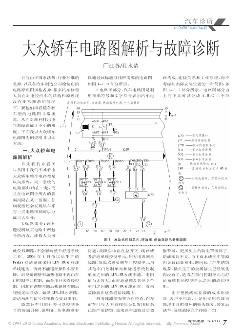
2.电路图部分:汽车电路图是利 图 1-(二)部分所示。电路图部分由
人员在对电控汽车的结构和原理还 用图形符号和文字符号表示汽车电 上 而 下 又 可 以 分 成 A、B、C 三 个 部
没有非常熟悉的情况
发动机控制单元、喷油器、燃油泵继电器、空气质量计
下,要他们再看懂各种
30
车型的电路图非常困
15 ×
门控制单元控制,而是由开关直接控 值为无穷大。而舒适系统及其他 3 个 适系统其他控制单元之间的通信中
制,因此在调整左侧后视镜时右侧后 车门之间的 LIN-BUS 线正常,看来 断。
视镜无法联动。如果 LIN-BUS 断路, 故障就在这条通信线路上。
由于更换线束花费的成本比较
舒适系统的信号传输将会受到影响。
8/75 6/75X
502 500A 红棕 16.0 0.5
S1/5 蓝/黑 1.0
75X 75
红
6.0
a
图 5 大众轿车喇叭局部电路图
有 2 个主要的作用:a)每一个代码都 加了读图难度。为此,大众轿车电路
与一纵向电路相对应,连续的电路代 图采用“断线带号法”来续接电路。只
码对应汽车某一整个系统电路内容; 要把两个方框合并,就等于把电路连
图 1-B 所示部分是实际车身电 器和连线部分,它是利用图形符号和 文字符号在电路图上表示汽车电路 构成、连接关系和工作原理。电器元
4。若有的插头上带有 a 则表示该元 件上 80 孔的插头不止一个,因此用 后缀 a、b、c 加以区分。
(3)电路图最底部横线
出,在实际汽车中是压装在中央电器 件在电路图中是主体,其在图中用框
②
C
(三)
图 1 发动机控制单元、喷油器、燃油泵继电器电路图
Q7 RSE Plus 电路图

版本 2008 年 4 月Rear Seat Entertainment (RSE)plus / 高级版后座 DVD 多媒体系统自 2007 年 11 月起说明:关于继电器及保险丝位置多芯插头连接控制器和继电器接地连接→安装位置一览!关于故障查找程序→导航型故障查询程序ws=白色sw =黑色ro =红色br =褐色gn =绿色bl =蓝色gr =灰色li =淡紫色ge =黄色or =橘黄色rs=粉红色拖车识别装置控制器,保险丝J345 -拖车识别装置控制器SD5 - 保险丝架 D 上的保险丝 5SF5 - 保险丝架 F 上的保险丝 5SF8 - 保险丝架 F 上的保险丝 8SF9 - 保险丝架 F 上的保险丝 9SF12 - 保险丝架 F 上的保险丝 12T12c - 12 芯蓝色插头连接,在拖车识别控制器上T12d - 12 芯红色插头连接,在拖车识别控制器上T16e - 16 芯插头连接,在拖车行驶识别装置控制器上51-行李箱内的右侧接地点 390 -接地连接 25,在主导线束中 B302-正极连接 6(30),在主导线束中* - 不带拖车挂钩的车辆** - 带拖车挂钩的车辆# -继电器,在驾驶员座椅下的保险丝架上ws=白色sw=黑色ro=红色br=褐色gn=绿色bl=蓝色gr=灰色li=淡紫色ge=黄色or=橘黄色rs=粉红色多媒体系统控制器J329 -端子 Kl. 15 供电继电器J650 -多媒体系统控制器SB6 -保险丝架 B 上的保险丝 6T2be -2芯黑色插头连接,在拖车识别控制器上T4ai -4芯黑色插头连接,在行李箱内右侧T26e -26 芯黑色插头连接,在多媒体系统控制器上U10 -带拖车行驶插座B165-正极连接 2(15),在车内导线束中B273-正极连接(15),在主导线束中B492-正极连接 3(15),在车内导线束中X78-连接 1,在选装装备导线束中* -不带拖车挂钩的车辆** -带拖车挂钩的车辆# -继电器,在驾驶员座椅下的保险丝架上ws=白色sw=黑色ro=红色br=褐色gn=绿色bl=蓝色gr=灰色li=淡紫色ge=黄色or=橘黄色rs=粉红色多媒体系统控制器、多媒体系统左耳机J650 -多媒体系统控制器R123 -多媒体系统左耳机T12x -12 芯黑色插头连接,在后中控台中T26e -26 芯黑色插头连接,在多媒体系统控制器上ws=白色sw=黑色ro=红色br=褐色gn=绿色bl=蓝色gr=灰色li=淡紫色ge=黄色or=橘黄色rs=粉红色多媒体系统控制器、多媒体系统右耳机、图像和音频辅助连接单元J650 -多媒体系统控制器R124 -多媒体系统右耳机R176 -音像系统辅助连接单元T12x -12 芯黑色插头连接,在后中控台中T12y -12 芯黑色插头连接,在后中控台中T26e -26 芯黑色插头连接,在多媒体系统控制器上ws=白色sw=黑色ro=红色br=褐色gn=绿色bl=蓝色gr=灰色li=淡紫色ge=黄色or=橘黄色rs=粉红色多媒体系统控制器、图像和音频辅助连接单元J650 -多媒体系统控制器R176 -音像系统辅助连接单元T12y -12 芯黑色插头连接,在后中控台中T26e -26 芯黑色插头连接,在多媒体系统控制器上ws=白色sw=黑色ro=红色br=褐色gn=绿色bl=蓝色gr=灰色li=淡紫色ge=黄色or=橘黄色rs=粉红色多媒体控制器、后部 DVD 转换盒J650 -多媒体系统控制器R162 -后部 DVD 转换盒T12v -12 芯黑色插头连接,在 DVD 光盘转换盒上T26d -26 芯绿色插头连接,在多媒体系统控制器上ws=白色sw=黑色ro=红色br=褐色gn=绿色bl=蓝色gr=灰色li=淡紫色ge=黄色or=橘黄色rs=粉红色多媒体系统控制器、多媒体系统显示单元 1J650 -多媒体系统控制器T2ba -2芯黑色插头连接,在驾驶员座椅下T6ak -6芯黑色插头连接,在驾驶员座椅下T7a -7芯插头连接,在驾驶员座椅靠背中T12w -12 芯黑色插头连接,在行李箱中后左侧T26d -26 芯绿色插头连接,在多媒体系统控制器上Y22 -多媒体系统显示单元 1ws=白色sw=黑色ro=红色br=褐色gn=绿色bl=蓝色gr=灰色li=淡紫色ge=黄色or=橘黄色rs=粉红色多媒体系统控制器、多媒体系统显示单元 2J650 -多媒体系统控制器T2bb -2芯黑色插头连接,在副驾驶员座椅下T6al -6芯黑色插头连接,在副驾驶员座椅下T7b -7芯插头连接,在副驾驶员座椅靠背中T26d -26 芯绿色插头连接,在多媒体系统控制器上Y23 -多媒体系统显示单元 2ws=白色sw=黑色ro=红色br=褐色gn=绿色bl=蓝色gr=灰色li=淡紫色ge=黄色or=橘黄色rs=粉红色多媒体系统控制器、电视调谐器J650 -多媒体系统控制器R78 -电视调谐器T18a -18 芯黑色插头连接,在多媒体系统控制器上T20p -20 芯插头连接,在电视调谐器上ws=白色sw=黑色ro=红色br=褐色gn=绿色bl=蓝色gr=灰色li=淡紫色ge=黄色or=橘黄色rs=粉红色多媒体系统控制器、电视调谐器J650 -多媒体系统控制器R78 -电视调谐器SD3 -保险丝架 D 上的保险丝 3SF6 -保险丝架 F 上的保险丝 6SF8 -保险丝架 F 上的保险丝 8T6am -6芯蓝色插头连接,在行李箱中左侧T18a -18 芯黑色插头连接,在多媒体系统控制器上T20p -20 芯插头连接,在电视调谐器上370-接地连接 5,在主导线束中675-接地点 2,在行李箱中右侧* -继电器,在驾驶员座椅下的保险丝架上? -L WL - 光缆,见信息娱乐系统数据总线(Most Ring)电路图ws=白色sw=黑色ro=红色br=褐色gn=绿色bl=蓝色gr=灰色li=淡紫色ge=黄色or=橘黄色rs=粉红色前部信息显示和操作单元的控制器,保险丝J523 -前部信息显示和操作单元的控制器J533 -数据总线诊断接口J685 -前部信息显示和操作单元控制器的显示单元SC6 -保险丝架 C 上的保险丝 6SD2 -保险丝架 D 上的保险丝 2T20k -20 芯红色插头连接,插头 A,在前部信息显示和操作单元的控制器上T22a -22 芯插头连接,在前部信息显示和操作单元控制器的显示单元上T22b -22 芯插头连接,插头 C,在前部信息显示和操作单元的控制器上T26b -26 芯黑色插头连接,插头 B,在数据总线诊断接口上45-中部仪表板后面的接地点373-接地连接 8,在主导线束中B300-正极连接 4(30),在主导线束中B444-连接 1(诊断),在主导线束中(环形结构断裂诊断)* -继电器,在驾驶员座椅下的保险丝架上? -L WL - 光缆,见信息娱乐系统数据总线(Most Ring)电路图ws=白色sw=黑色ro=红色br=褐色gn=绿色bl=蓝色gr=灰色li=淡紫色ge=黄色or=橘黄色rs=粉红色前部信息显示和操作单元的控制器,多媒体系统操作单元,手套箱按键,显示单元按键E316 -手套箱按钮E380 -多媒体系统操作单元E506 -显示单元按钮J285 -仪表板中的控制器J520 -车载电网控制器 2J523 -前部信息显示和操作单元的控制器T6w -6芯黑色插头连接,在开关模块侧面T16f -16 芯棕色插头连接, 在多媒体系统操作单元上T20k -20 芯红色插头连接,插头 A,在前部信息显示和操作单元的控制器上T32a -32 芯灰色插头连接,在组合仪表中的控制器上T40a -40 芯黑色插头连接,在车载电网控制器 2 上45-中部仪表板后面的接地点378-接地连接 13,在主导线束中B340-连接 1(58s),在主导线束中B341-连接 2(58s),在主导线束中。
2016--2013一汽奥迪Q3电路图资料-36-电视调谐器

04.2014电视调谐器(MOST 总线)自2011 年8 月起ws=白色sw =黑色ro =红色rt =红色br =褐色gn =绿色bl =蓝色gr =灰色li =淡紫色vi =淡紫色ge =黄色or =橘黄色rs =粉红色保险丝架C J532 - 稳压器仅,稳上自紫 保险丝架 C上的保险丝 18SC33 - 保险丝架C 上的保险丝 33ws=白色sw =黑色ro =红色rt =红色br =褐色gn =绿色bl =蓝色gr =灰色li =淡紫色vi =淡紫色ge =黄色or =橘黄色rs =粉红色倒车摄像系统控制单元, 电子通讯信息设备1 控制单元, 电视调谐器 J772 - 倒车摄像系统控制单元T2aa - 2 芯插头连接T2df - 2 芯插头连接T2do - 2 芯插头连接T2z - 2 芯插头连接T12x - 12 芯插头连接T20l- 20 芯插头连接 57- 接地点,在左后柱上ws =白色sw =黑色ro =红色rt =红色br =褐色gn =绿色bl =蓝色gr =灰色li =淡紫色vi =淡紫色ge =黄色or =橘黄色rs=粉红色天线放大器,电视调谐器, 天线放大器 2, 天线放大器 4, 电视读卡器 R - 收音机R111 - 天线放大器 2R113 - 天线放大器 4R204 -电视读卡器T2i - 2 芯插头连接T4aa - 4 芯插头连接T4ah - 4 芯插头连接T4ai - 4 芯插头连接T4w - 4 芯插头连接T4x - 4 芯插头连接T4y - 4 芯插头连接T4z -4 芯插头连接* -仅适用于带有日本版装备的汽车*2 -仅适用于带韩国版装备的汽车*3 - 依汽车装备而定*4- 仅适用于带 MMI 的汽车J794 - 电子通讯信息设备 1 控制单元R78- 电视调谐器384 - 接地连接 19,在主导线束中 H20- 连接 1,在诊断导线束中*-依汽车装备而定*2 - 不适用于带韩国版装备的汽车*3 - 见适用于信息娱乐系统 MOST 总线的电路图*4 -仅适用于不带倒车摄像机系统的汽车*5 - 仅适用于带倒车摄像机系统的汽车*6 - 截至 2014 年 4 月*7 - 见适用于环形结构断裂诊断的电路图*8- 自 2014 年 5 月起ws=白色sw =黑色ro =红色rt =红色br =褐色gn =绿色bl =蓝色gr =灰色li =淡紫色vi =淡紫色ge =黄色or =橘黄色rs =粉红色天线放大器, 电视调谐器, 天线放大器 2 R - 收音机R111 - 天线放大器 2T2ab - 2 芯插头连接T4ab - 4 芯插头连接T4w - 4 芯插头连接T4z - 4 芯插头连接* - 仅适用于带 MMI 的汽车。
奥迪Q7电路图-空调-舒适

Edition 02.2006 Convenience air conditioning systemfrom model year 2007Notes:For information concerningPosition of relays and fusesMulti-pin connectionsControl units and relaysEarth connections→ List of Fitting Locations!For information concerningFault Finding Programs→ guided fault findingws=white sw =black ro =red br =brown gn =green bl =blue gr =grey li =purple ge =yellow or =orange rs=pinkClimatronic control unit, fuses J255 - C limatronic control unit J329 - T erminal 15 voltage supply relay SC8 - F use 8 on fuse holder C SC10 - F use 10 on fuse holder C SC12 - F use 12 on fuse holder C SD2 - F use 2 on fuse holder DT16c - 16-pin connector, brown, connector C, on Climatronic controlunitT16d - 16-pin connector, black, connector D, on Climatronic controlunitT46b - 46-pin connector, black, CAN separating connector right45-Earth point, centre behind dash panel 378 -Earth connection 13, in main wiring harness B163 -Positive connection 1 (15), in interior wiring harness B273 -Positive connection (15), in main wiring harness B280-Positive connection 4 (15a), in main wiring harness B300 -Positive connection 4 (30), in main wiring harness B322-Positive connection 8 (30a), in main wiring harness• - C AN bus (data wire)* - o nly with operating and display unit for rear Climatronic ** - F use and relay carrier under driver seatws=whitesw=blackro=redbr=browngn=greenbl=bluegr=greyli=purplege=yellowor=orangers=pinkClimatronic control unit, air quality sensor, fresh air blowercontrol unit, fresh air blower, fresh air blower fuse 1 and 2C24 -S uppression filterG238 -A ir quality sensorJ126 -F resh air blower control unitJ255 -C limatronic control unitS97 -F resh air blower fuse 1S98 -F resh air blower fuse 2S123 -A BS control unit fuse 1SD1 -F use 1 on fuse holder DT2q -2-pin connector, on fresh air blower control unitT4t -4-pin connector, on fresh air blower control unitT16c -16-pin connector, brown, connector C, on Climatronic controlunitT16d -16-pin connector, black, connector D, on Climatronic controlunitT17k -17-pin connector, black, behind the dash panel, right, airconditioning systemV2 -F resh air blower43-Earth point, lower part of right A-pillarB272-Positive connection (30), in main wiring harness* -r elay and fuse carrier centre dash panel** -R elay and fuse carrier under driver seatws=whitesw=blackro=redbr=browngn=greenbl=bluegr=greyli=purplege=yellowor=orangers=pinkClimatronic control unit, front seat temperature sender, front seatheatingG344 -F ront left seat temperature senderG345 -F ront right seat temperature senderJ255 -C limatronic control unitSC3 -F use 3 on fuse holder CT2ao -2-pin connector, black, under the seat on front leftT2ap -2-pin connector, black, under the seat on front rightT3c -3-pin connector, black, connector E, on Climatronic controlunitT6f -6-pin connector, green, under driver seatT6g -6-pin connector, green, under front passenger seatT16d -16-pin connector, black, connector D, on Climatronic controlunitZ7 -H eated driver seat backrestZ9 -H eated front passenger seat backrestZ45 -F ront left seat heatingZ46 -F ront right seat heating77-Earth point, lower part of left B-pillar78-Earth point, lower part of right B-pillar366-Earth connection 1, in main wiring harness379-Earth connection 14, in main wiring harnessB299-Positive connection 3 (30), in main wiring harness* -m odels with seat heatingws=whitesw=blackro=redbr=browngn=greenbl=bluegr=greyli=purplege=yellowor=orangers=pinkClimatronic control unit, sunlight penetration photosensor,refrigerant temperature sender, compressor regulating valve, airconditioning system compressor regulating valveG107 -S unlight penetration photosensorG454 -R efrigerant temperature senderJ255 -C limatronic control unitN280 -A ir conditioning system compressor regulating valveT10d -10-pin connector, blue, coupling station on electronics box,plenum chamberT10f -10-pin connector, red, coupling station on electronics box,plenum chamberT16c -16-pin connector, brown, connector C, on Climatronic controlunitT16d -16-pin connector, black, connector D, on Climatronic controlunit379-Earth connection 14, in main wiring harness* -O utput sender earthws =white sw =black ro =red br =brown gn =green bl =blue gr =grey li =purple ge =yellow or =orange rs =pinkClimatronic control unit, high pressure sender G65 - H igh pressure sender J255 - C limatronic control unit J271 - M otronic current supply relay J317 - T erminal 30 voltage supply relay S10 - F uses in relay plate fuse holder S13 - F uses in relay plate fuse holderT10d - 10-pin connector, blue, coupling station on electronics box,plenum chamberT16d - 16-pin connector, black, connector D, on Climatronic controlunit85-Earth connection 1, in engine compartment wiring harness609 -Earth point, on right in plenum chamberD101 -Connection 1, in engine compartment wiring harness D102 -Connection 2, in engine compartment wiring harness D107-Connection 5, in engine compartment wiring harnessD109-Connection 7, in engine compartment wiring harness * - 4.2 l engine, engine code BAR** - 3,0 l Diesel engine, engine codes BUN, BUG # - R elay and fuse carrier, electronics box plenum chamberws=whitesw=blackro=redbr=browngn=greenbl=bluegr=greyli=purplege=yellowor=orangers=pinkClimatronic control unit, continued coolant circulation relay,coolant circulation pumpJ151 -C ontinued coolant circulation relayJ255 -C limatronic control unitJ623 -E ngine control unitJ749 -F uel pump relay for auxiliary heaterT6k -6-pin connector, brown, coupling station on electronics box,plenum chamberT10c -10-pin connector, pink, coupling station on electronics box,plenum chamberT10d -10-pin connector, blue, coupling station on electronics box,plenum chamberT16c -16-pin connector, brown, connector C, on Climatronic controlunitT16d -16-pin connector, black, connector D, on Climatronic controlunitT94 -94-pin connector, black, on engine control unitV50 -C oolant circulation pump368-Earth connection 3, in main wiring harness640-Earth point, left in engine compartmentB537-Connection 28, in main wiring harness* -4.2 l engine, engine code BAR** -3,0 l Diesel engine, engine codes BUN, BUG# -r elay and fuse carrier centre dash panel## -m odels with auxiliary heater### -R elay and fuse carrier, electronics box plenum chamberws=whitesw=blackro=redbr=browngn=greenbl=bluegr=greyli=purplege=yellowor=orangers=pinkClimatronic control unit, fresh air intake duct temperature sensor,footwell vent temperature sender, evaporator output temperaturesender, front chest vent temperature sensorG89 -F resh air intake duct temperature sensorG261 -L eft footwell vent temperature senderG262 -R ight footwell vent temperature senderG263 -E vaporator output temperature senderG385 -F ront left chest vent temperature sensorG386 -F ront right chest vent temperature sensorJ255 -C limatronic control unitT12g -12-pin connector, connector A, on Climatronic control unitT16d -16-pin connector, black, connector D, on Climatronic controlunitT17k -17-pin connector, black, behind the dash panel, right, airconditioning systemT20i -20-pin connector, red, connector B, on Climatronic controlunit97-Earth connection 1, in air conditioning system wiring harness * -O utput sender earthws=whitesw=blackro=redbr=browngn=greenbl=bluegr=greyli=purplege=yellowor=orangers=pinkClimatronic control unit, defroster flap control motorpotentiometer, air recirculation flap control motor potentiometer,potentiometer for right temperature flap control motor, dash paneltemperature sensorG56 -D ash panel temperature sensorG135 -D efroster flap control motor potentiometerG143 -A ir recirculation flap control motor potentiometerG221 -P otentiometer for right temperature flap control motorJ255 -C limatronic control unitT12g -12-pin connector, connector A, on Climatronic control unitT16c -16-pin connector, brown, connector C, on Climatronic controlunitT16d -16-pin connector, black, connector D, on Climatronic controlunitT17k -17-pin connector, black, behind the dash panel, right, airconditioning systemT20i -20-pin connector, red, connector B, on Climatronic controlunitV42 -T emperature sensor blowerV107 -D efroster flap control motorV113 -A ir recirculation flap control motorV159 -R ight temperature flap control motor97-E arth connection 1, in air conditioning system wiring harness L31-Connection (5V), in air conditioning system wiring harnessws=whitesw=blackro=redbr=browngn=greenbl=bluegr=greyli=purplege=yellowor=orangers=pinkClimatronic control unit, potentiometer for right centre ventcontrol motor, potentiometer for indirect ventilation flap controlmotorG137 -P otentiometer for right centre vent control motorG330 -P otentiometer for indirect ventilation flap control motorJ255 -C limatronic control unitT12g -12-pin connector, connector A, on Climatronic control unitT16c -16-pin connector, brown, connector C, on Climatronic controlunitT17k -17-pin connector, black, behind the dash panel, right, airconditioning systemT20i -20-pin connector, red, connector B, on Climatronic controlunitV111 -R ight central vents control motorV213 -I ndirect ventilation flap control motor97-Earth connection 1, in air conditioning system wiring harness L9-Connection 1, in air conditioning system wiring harness L10-Connection 2, in air conditioning system wiring harness L31-Connection (5V), in air conditioning system wiring harness* -l eft-hand drive** -R ight-hand drivews=whitesw=blackro=redbr=browngn=greenbl=bluegr=greyli=purplege=yellowor=orangers=pinkClimatronic control unit, potentiometer for right footwell flapcontrol motor, potentiometer for left side vent control motor,potentiometer for right side vent control motorG140 -P otentiometer for right footwell flap control motorG164 -P otentiometer for left side vent control motorG523 -P otentiometer for right side vent control motorJ255 -C limatronic control unitT12g -12-pin connector, connector A, on Climatronic control unitT20i -20-pin connector, red, connector B, on Climatronic controlunitV109 -R ight footwell flap control motorV299 -L eft side vent control motorV300 -R ight side vent control motor97-Earth connection 1, in air conditioning system wiring harness L10-Connection 2, in air conditioning system wiring harness L11-Connection 3, in air conditioning system wiring harness L31-Connection (5V), in air conditioning system wiring harnessws=whitesw=blackro=redbr=browngn=greenbl=bluegr=greyli=purplege=yellowor=orangers=pinkClimatronic control unit, potentiometer for left centre vent controlmotor, potentiometer for left footwell flap control motor,potentiometer for left temperature flap control motorG136 -P otentiometer for left centre vent control motorG139 -P otentiometer for left footwell flap control motorG220 -P otentiometer for left temperature flap control motorJ255 -C limatronic control unitT12g -12-pin connector, connector A, on Climatronic control unitT20i -20-pin connector, red, connector B, on Climatronic controlunitV108 -L eft footwell flap control motorV110 -L eft centre vent control motorV158 -L eft temperature flap control motor97-Earth connection 1, in air conditioning system wiring harness L31-Connection (5V), in air conditioning system wiring harnessws=whitesw=blackro=redbr=browngn=greenbl=bluegr=greyli=purplege=yellowor=orangers=pinkOperating and display unit for rear Climatronic, fusesE265 -O perating and display unit for rear ClimatronicSC8 -F use 8 on fuse holder CSC12 -F use 12 on fuse holder CT16h -16-pin connector, connector D, on rear Climatronic operatingand display unitT46b -46-pin connector, black, CAN separating connector right687-Earth point 1, on centre tunnelB319-Positive connection 5 (30a), in main wiring harness• -C AN bus (data wire)* -o ptional equipmentws=white sw =black ro =red br =brown gn =green bl =blue gr =grey li =purple ge =yellow or =orange rs=pinkRear Climatronic operating and display unit, rear left seattemperature sensor, rear seat occupied sensor on driver side, heated rear left seat E128 - H eated rear left seat switch with regulator E265 - O perating and display unit for rear Climatronic G94 - R ear left seat temperature sensor G177 - R ear seat occupied sensor on driver side SC1 - F use 1 on fuse holder CT3h - 3-pin connector, black, connector E, on rear Climatronicoperating and display unitT6h - 6-pin connector, green, under rear seat, left T8s - 8-connector, black, in rear seat, leftT12h - 12-pin connector, connector A, on rear Climatronic operatingand display unitT16h - 16-pin connector, connector D, on rear Climatronic operatingand display unitZ10 - H eated rear left seat Z11 - H eated rear left seat backrest61-Earth point, left C-pillar 411-Earth connection 2 (sender earth), in main wiring harness* - o ptional equipment ** - m odels with seat heatingws=whitesw=blackro=redbr=browngn=greenbl=bluegr=greyli=purplege=yellowor=orangers=pinkRear Climatronic operating and display unit, rear right seattemperature sensor, rear seat occupied sensor on front passengerside, heated rear right seatE129 -H eated rear right seat switch with regulatorE265 -O perating and display unit for rear ClimatronicG95 -R ear right seat temperature sensorG178 -R ear seat occupied sensor on front passenger sideT3h -3-pin connector, black, connector E, on rear Climatronicoperating and display unitT6i -6-pin connector, green, under rear seat, rightT8t -8-connector, black, in rear seat, rightT12h -12-pin connector, connector A, on rear Climatronic operatingand display unitT16h -16-pin connector, connector D, on rear Climatronic operatingand display unitZ12 -H eated rear right seatZ13 -H eated rear right seat backrest78-Earth point, lower part of right B-pillar391-Earth connection 26, in main wiring harness411-Earth connection 2 (sender earth), in main wiring harness* -o ptional equipment** -m odels with seat heatingws=whitesw=blackro=redbr=browngn=greenbl=bluegr=greyli=purplege=yellowor=orangers=pinkOperating and display unit for rear Climatronic, rear fresh airblower control unit, rear vent temperature sender, rear fresh airblowerC24 -S uppression filterE265 -O perating and display unit for rear ClimatronicG405 -R ear left vent temperature senderG406 -R ear right vent temperature senderJ391 -R ear fresh air blower control unitT2r -2-pin connector, on rear fresh air blower control unitT4u -4-pin connector, on rear fresh air blower control unitT12h -12-pin connector, connector A, on rear Climatronic operatingand display unitT16h -16-pin connector, connector D, on rear Climatronic operatingand display unitT17h -17-pin connector, black, rear centre consoleV80 -R ear fresh air blower61-Earth point, left C-pillar112-Earth connection 2, in air conditioning system wiring harness * -o ptional equipmentws=whitesw=blackro=redbr=browngn=greenbl=bluegr=greyli=purplege=yellowor=orangers=pinkRear Climatronic operating and display unit, potentiometer forrear left air quantity flap, rear left temperature flap potentiometerE265 -O perating and display unit for rear ClimatronicG389 -R ear left air quantity flap potentiometerG390 -R ear right air quantity flap potentiometerG391 -R ear left temperature flap potentiometerT12h -12-pin connector, connector A, on rear Climatronic operatingand display unitT12k -12-pin connector, rear centre consoleT20h -20-pin connector, red, connector B, on rear Climatronicoperating and display unitV239 -R ear left air quantity flap control motorV240 -R ear right air quantity flap control motorV313 -R ear left temperature flap control motorL46-Connection (5 Volt), in Climatronic operating unit wiringharnessL68-Connection 2 (sender), in Climatronic wiring harness* -o ptional equipmentws=whitesw=blackro=redbr=browngn=greenbl=bluegr=greyli=purplege=yellowor=orangers=pinkRear Climatronic operating and display unit, rear righttemperature flap potentiometer, rear left chest vent potentiometerE265 -O perating and display unit for rear ClimatronicG392 -R ear right temperature flap potentiometerG471 -R ear left chest vent potentiometerT12h -12-pin connector, connector A, on rear Climatronic operatingand display unitT12k -12-pin connector, rear centre consoleT17h -17-pin connector, black, rear centre consoleT20h -20-pin connector, red, connector B, on rear Climatronicoperating and display unitV314 -R ear right temperature flap control motorV315 -R ear left chest vent control motor376-Earth connection 11, in main wiring harnessB369-Connection 1 (5V), in main wiring harnessL46-Connection (5 Volt), in Climatronic operating unit wiringharnessL68-Connection 2 (sender), in Climatronic wiring harness* -o ptional equipment** -o utput signal earthws=whitesw=blackro=redbr=browngn=greenbl=bluegr=greyli=purplege=yellowor=orangers=pinkOperating and display unit for rear Climatronic, potentiometer forright B-pillar and footwell shut-off flap control motor, rear rightchest vent potentiometerE265 -O perating and display unit for rear ClimatronicG328 -Potentiometer for right B-pillar and footwell shut-off flapcontrol motorG329 -Potentiometer for left B-pillar and footwell shut-off flap controlmotorG472 -R ear right chest vent potentiometerT12h -12-pin connector, connector A, on rear Climatronic operatingand display unitT20h -20-pin connector, red, connector B, on rear Climatronicoperating and display unitV211 -R ight B-pillar and footwell shut-off flap control motorV212 -L eft B-pillar and footwell shut-off flap control motorV316 -R ear right chest vent control motor376-Earth connection 11, in main wiring harnessB369-Connection 1 (5V), in main wiring harness* -o ptional equipmentws =white sw =black ro =red br =brown gn =green bl =blue gr =grey li =purple ge =yellow or =orange rs=pinkDash panel left vent illumination bulb, dash panel central vent illumination bulb, dash panel right vent illumination bulb, central rear vent illumination bulb J285 - C ontrol unit in dash panel insert L67 - D ash panel left vent illumination bulb L68 - D ash panel central vent illumination bulb L69 - D ash panel right vent illumination bulb L87 - C entral rear vent illumination bulb T32a - 32-pin connector, grey, on control unit in dash panel insert43-Earth point, lower part of right A-pillar44 -Earth point, lower part of left A-pillar 67 -Earth point, on left of front cross member 371 -Earth connection 6, in main wiring harness 377 -Earth connection 12, in main wiring harness 383-Earth connection 18, in main wiring harnessB340-Connection 1 (58s), in main wiring harness B341-Connection 2 (58s), in main wiring harness。
奥迪Q7电路图-继电器及保险丝位置

Edition 02.2006Position of relays and fusesPosition of fuses in fuse carrier, left dash panelFuse colours40 A - orange 30 A - green 25 A - white 20 A - yellow 15 A - blue 10 A - red 7,5 A - brown 5 A - beige 3 A - purple1 - Fuse carrier ST1 (red)2 - Fuse carrier ST2 (brown)3 - Fuse carrier ST3 (black)4 - CAN separating connector T46a - A up to D - vacantPosition of fuses in fuse carrier, left dash panel (left-hand drive)No.Current Flow Diagram designation Fuse carrier ST1 (red)NominalvalueFunction/component Terminal1-SB1 - Fuse 1 on fuse holder B--Vacant2-SB2 - Fuse 2 on fuse holder B--Vacant3-SB3 - Fuse 3 on fuse holder B--Vacant4-SB4 - Fuse 4 on fuse holder B 5 A-J502-Tyre pressure monitor control unit30 5-SB5 - Fuse 5 on fuse holder B20 A-J364 -Auxiliary heater control unit30 6-SB6 - Fuse 6 on fuse holder B10 A-E176-Driver seat lumbar support adjustment switch30 7-SB7 - Fuse 7 on fuse holder B35 A-J386-Driver door control unitV147-Driver side window regulator motorJ388-Rear left door control unitV26-Rear left window regulator motor308-SB8 - Fuse 8 on fuse holder B15 A-J386-Driver door control unitJ388-Rear left door control unit30 9-SB9 - Fuse 9 on fuse holder B 5 A-J644-Energy management control unit3010-SB10 - Fuse 10 on fuse holder B30 A-J518-Entry and start authorisation control unitE415-Entry and start authorisation switch30 11-SB11 - Fuse 11 on fuse holder B10 A-J527-Steering column electronics control unit3012-SB12 - Fuse 12 on fuse holder B 5 A-G273- Interior monitoring sensorH12- Alarm horn30Position of fuses in fuse carrier, left dash panel (left-hand drive)No.Current Flow Diagram designation Fuse carrier ST2 (brown)NominalvalueFunction/component Terminal1-SB1 - Fuse 1 on fuse holder B--Vacant2-SB2 - Fuse 2 on fuse holder B--Vacant3-SB3 - Fuse 3 on fuse holder B--Vacant4-SB4 - Fuse 4 on fuse holder B30 A-J400-Wiper motor control unitV-Windscreen wiper motor30 5-SB5 - Fuse 5 on fuse holder B 5 A-G397- Rain and light detector sensor306-SB6 - Fuse 6 on fuse holder B25 A-J4-Dual tone horn relayH2-Treble tone hornH7-Bass tone horn307-SB7 - Fuse 7 on fuse holder B30 A-J519-Onboard power supply control unit30 8-SB8 - Fuse 8 on fuse holder B25 A-J519-Onboard power supply control unit30 9-SB9 - Fuse 9 on fuse holder B25 A-J519-Onboard power supply control unit30 10-SB10 - Fuse 10 on fuse holder B10 A-J285-Control unit in dash panel insertY24-Display in dash panel insert30 11-SB11 - Fuse 11 on fuse holder B30 A-J39 -Headlight washer system relay30 12-SB12 - Fuse 12 on fuse holder B10 A-T16-Diagnostic connector30Position of fuses in fuse carrier, left dash panel (left-hand drive)No.Current Flow Diagram designation Fuse carrier ST3 (black)NominalvalueFunction/component Terminal1-SB1 - Fuse 1 on fuse holder B10 A-J745-Cornering light and headlight rangecontrol unit152-SB2 - Fuse 2 on fuse holder B 5 A-J428-Adaptive cruise control unitZ47-Sensor heater for adaptive cruisecontrol system153-SB3 - Fuse 3 on fuse holder B--Vacant4-SB4 - Fuse 4 on fuse holder B10 A-Lane-Departure-WarningJ759-Lane departure warning control unitZ67-Windscreen heater for lanedeparture warning155-SB5 - Fuse 5 on fuse holder B--Vacant6-SB6 - Fuse 6 on fuse holder B 5 A-J527-Steering column electronics controlunitJ518-Entry and start authorisation controlunitE1-Light switchJ393-Convenience system central controlunitJ345-Trailer detector control unit157-SB7 - Fuse 7 on fuse holder B 5 A-G226 -Oil level and oil temperaturesender15 8-SB8 - Fuse 8 on fuse holder B 5 A-T16-Diagnostic connector15 9-SB9 - Fuse 9 on fuse holder B 5 A-Y7 -Automatic anti-dazzle interior mirror15 10-SB10 - Fuse 10 on fuse holder B 5 A-J530-Garage door operation control unitE284-Garage door operating unit15 11-SB11 - Fuse 11 on fuse holder B 5 A-J533-Data bus diagnostic interface1512-SB12 - Fuse 12 on fuse holder B 5 A-E102-Headlight range control regulatorV48 -Left headlight range control motorV49 -Right headlight range control motor15Position of fuses in fuse carrier, left dash panel (right-hand drive)No.Current Flow Diagram designation Fuse carrier ST1 (red)NominalvalueFunction/component Terminal1-SB1 - Fuse 1 on fuse holder B--Vacant2-SB2 - Fuse 2 on fuse holder B--Vacant3-SB3 - Fuse 3 on fuse holder B--Vacant4-SB4 - Fuse 4 on fuse holder B 5 A-J502-Tyre pressure monitor control unit30 5-SB5 - Fuse 5 on fuse holder B20 A-J364 -Auxiliary heater control unit30 6-SB6 - Fuse 6 on fuse holder B10 A-E177-Front passenger seat lumbarsupport adjustment switch307-SB7 - Fuse 7 on fuse holder B35 A-J387-Front passenger side door controlunit308-SB8 - Fuse 8 on fuse holder B15 A-J387-Front passenger door control unitV148-Front passenger side windowregulator motorJ389-Rear right door control unitV27-Rear right window regulator motor309-SB9 - Fuse 9 on fuse holder B 5 A-J644-Energy management control unitJ389-Rear right door control unit3010-SB10 - Fuse 10 on fuse holder B 5 A-R118-Media player in position 1R119-Media player in position 2R41-CD changerR153-Mini Disc playerR129-Video recorder and DVD player3011-SB11 - Fuse 11 on fuse holder B10 A-E265-Rear Climatronic operating anddisplay unitJ391-Rear fresh air blower control unit3012-SB12 - Fuse 12 on fuse holder B 5 A-J393-Convenience system central controlunit30Position of fuses in fuse carrier, left dash panel (right-hand drive)No.Current Flow Diagram designation Fuse carrier ST2 (brown)NominalvalueFunction/component Terminal1-SB1 - Fuse 1 on fuse holder B--Vacant2-SB2 - Fuse 2 on fuse holder B--Vacant3-SB3 - Fuse 3 on fuse holder B--Vacant4-SB4 - Fuse 4 on fuse holder B30 A-J400-Wiper motor control unitV-Windscreen wiper motor30 5-SB5 - Fuse 5 on fuse holder B 5 A-G397- Rain and light detector sensor306-SB6 - Fuse 6 on fuse holder B25 A-H2 -Treble tone hornH7 - Bass tone hornJ4 -Dual tone horn relay307SB7 - Fuse 7 on fuse holder B--Vacant8-SB8 - Fuse 8 on fuse holder B20 A-U1-Cigarette lighter30 9-SB9 - Fuse 9 on fuse holder B25 A-U5 -12 V socketU18 -12 V socket 23010-SB10 - Fuse 10 on fuse holder B10 A-J255-Climatronic control unitJ126-Fresh air blower control unit30 11-SB11 - Fuse 11 on fuse holder B30 A-J39 -Headlight washer system relay30 12-SB12 - Fuse 12 on fuse holder B10 A-T16-Diagnostic connector30Position of fuses in fuse carrier, left dash panel (right-hand drive)No.Current Flow Diagram designation Fuse carrier ST3 (black)NominalvalueFunction/component Terminal1-SB1 - Fuse 1 on fuse holder B10 A-J745-Cornering light and headlight rangecontrol unit152-SB2 - Fuse 2 on fuse holder B 5 A-J428-Adaptive cruise control unitZ47-Sensor heater for adaptive cruisecontrol system153-SB3 - Fuse 3 on fuse holder B--Vacant4-SB4 - Fuse 4 on fuse holder B10 A-J759-Lane departure warning control unitZ67-Windscreen heater for lanedeparture warning155-SB5 - Fuse 5 on fuse holder B--Vacant6- SB6 - Fuse 6 on fuse holder B 5 A-Z10-Heated bench seat cushion for rearleft seatZ11-Heated rear left seat backrestZ12-Heated bench seat cushion for rearright seatZ13-Heated backrest for rear right seat157-SB7 - Fuse 7 on fuse holder B 5 A-G226 -Oil level and oil temperaturesender15 8-SB8 - Fuse 8 on fuse holder B 5 A-T16-Diagnostic connector15 9-SB9 - Fuse 9 on fuse holder B 5 A-Y7 -Automatic anti-dazzle interior mirror15 10-SB10 - Fuse 10 on fuse holder B 5 A-J530-Garage door operation control unitE284-Garage door operating unit15 11-SB11 - Fuse 11 on fuse holder B 5 A-J234-Airbag control unit1512-SB12 - Fuse 12 on fuse holder B 5 A-G238-Air quality sensorE265-Rear Climatronic operating anddisplay unitJ255-Climatronic control unit15Position of fuses in fuse carrier, right dash panelFuse colours40 A - orange 30 A - green 25 A - white 20 A - yellow 15 A - blue 10 A - red 7,5 A - brown 5 A - beige 3 A - purple1 - Fuse carrier ST1 (black)2 - Fuse carrier ST2 (brown)3 - Fuse carrier ST3 (red)4 - CAN separating connector T46b - A up to D - vacantPosition of fuses in fuse carrier, right dash panel (left-hand drive)No.Current Flow Diagram designation Fuse carrier ST1 (black)NominalvalueFunction/component Terminal1-SC1 - Fuse 1 on fuse holder C20 A-Z10-Heated bench seat cushion for rearleft seatZ11-Heated rear left seat backrestZ12-Heated bench seat cushion for rearright seatZ13-Heated backrest for rear right seat302-SC2-Fuse 2 on fuse holder C 10 A-J217-Automatic gearbox control unit(0AT)305 A-J217-Automatic gearbox control unit(09D)303-SC3 - Fuse 3 on fuse holder C30 A-Z45-Heated seat cushion for front leftseatZ46-Heated seat cushion for front rightseat304-SC4 - Fuse 4 on fuse holder C20 A-J104 -ABS control unit30 5-SC5 - Fuse 5 on fuse holder C15 A-J387-Front passenger door control unitJ389-Rear right door control unit306-SC6 - Fuse 6 on fuse holder C25 A-U19-12 V socket 3U20-12 V socket 4307-SC7 - Fuse 7 on fuse holder C10 A-E177-Front passenger seat lumbarsupport adjustment switch30 8-SC8 - Fuse 8 on fuse holder C20 A-U1-Cigarette lighter309-SC9 - Fuse 9 on fuse holder C25 A-U5 -12 V socketU18 -12 V socket 23010-SC10 - Fuse 10 on fuse holder C10 A-J255-Climatronic control unitJ126-Fresh air blower control unit3011- SC11 - Fuse 11 on fuse holder C 5 A-F-Brake light switchF47-Brake pedal switchJ104-ABS control unit30 12-SC12 - Fuse 12 on fuse holder C15 A-J520-Onboard supply control unit 230Position of fuses in fuse carrier, right dash panel (left-hand drive)No.Current Flow Diagram designation Fuse carrier ST2 (brown)NominalvalueFunction/component Terminal1-SC1 - Fuse 1 on fuse holder C10 A-J745-Cornering light and headlight rangecontrol unit152-SC2 - Fuse 2 on fuse holder C 5 A-J197-Adaptive suspension control unit15 3-SC3 - Fuse 3 on fuse holder C--Vacant4-SC4 - Fuse 4 on fuse holder C 5 A-J769-Lane change assist control unitJ770-Lane change assist control unit 2155-SC5 - Fuse 5 on fuse holder C 5 A-J508-Brake light suppression relayF36-Clutch pedal switch156-SC6-Fuse 6 on fuse holder C5 A-J217-Automatic gearbox control unit(0AT)1520 A-J217-Automatic gearbox control unit(09D)157-SC7 - Fuse 7 on fuse holder C 5 A-J104 -ABS control unit15 8-SC8 - Fuse 8 on fuse holder C 5 A-F125-Multifunction switchF189-Tiptronic switchJ587-Selector lever sensors control unit159-SC9 - Fuse 9 on fuse holder C 5 A-J446-Parking aid control unit15 10-SC10 - Fuse 10 on fuse holder C 5 A-J234-Airbag control unit15 11-SC11 - Fuse 11 on fuse holder C 5 A-E128-Heated rear left seat switch withregulatorE129-Heated rear right seat switch withregulator1512-SC12 - Fuse 12 on fuse holder C 5 A-G238-Air quality sensorE265-Rear Climatronic operating anddisplay unitJ255-Climatronic control unit15Position of fuses in fuse carrier, right dash panel (left-hand drive)No.Current Flow Diagram designation Fuse carrier ST3 (red)NominalvalueFunction/component Terminal1-SC1 - Fuse 1 on fuse holder C15 A-V12 -Rear window wiper motor75 2-SC2 - Fuse 2 on fuse holder C 5 A-Z20 -Left washer jet heater elementZ21 -Right washer jet heater element75 3-SC3 - Fuse 3 on fuse holder C--Vacant4-SC4 - Fuse 4 on fuse holder C--Vacant5-SC5 - Fuse 5 on fuse holder C 5 A-R36-Telephone transmitter and receiverunit306-SC6-Fuse 6 on fuse holder C 15 A-J523-Front information display andoperating unit control unitR24-Aerial amplifier305 A-J523-Front information display andoperating unit control unit307-SC7 - Fuse 7 on fuse holder C20 A-J245-Sliding sunroof adjustment controlunit30 8-SC8 - Fuse 8 on fuse holder C20 A-J392-Rear sliding sunroof control unit30 9-SC9 - Fuse 9 on fuse holder C20 A-J394-Sunroof roller blind control unit30 10-SC10 - Fuse 10 on fuse holder C 5 A-R118-Media player in position 1R119-Media player in position 2R41-CD changerR153-Mini Disc playerR129-Video recorder and DVD player3011-SC11 - Fuse 11 on fuse holder C35 A-J387-Front passenger door control unitV148-Front passenger side windowregulator motorJ389-Rear right door control unitV27-Rear right window regulator motor3012-SC12 - Fuse 12 on fuse holder C10 A-E265-Rear Climatronic operating anddisplay unitJ391-Rear fresh air blower control unit30Position of fuses in fuse carrier, right dash panel (right-hand drive)No.Current Flow Diagram designation Fuse carrier ST1 (black)NominalvalueFunction/component Terminal1-SC1 - Fuse 1 on fuse holder C20 A-Z10-Heated bench seat cushion for rearleft seatZ11-Heated rear left seat backrestZ12-Heated bench seat cushion for rearright seatZ13-Heated backrest for rear right seat302-SC2-Fuse 2 on fuse holder C 10 A-J217-Automatic gearbox control unit(0AT)305 A-J217-Automatic gearbox control unit(09D)303-SC3 - Fuse 3 on fuse holder C30 A-Z45-Heated seat cushion for front leftseatZ46-Heated seat cushion for front rightseat304-SC4 - Fuse 4 on fuse holder C20 A-J104 -ABS control unit30 5-SC5 - Fuse 5 on fuse holder C15 A-J386-Driver door control unitJ388-Rear left door control unit306-SC6 - Fuse 6 on fuse holder C25 A-U19-12 V socket 3U20-12 V socket 4307-SC7 - Fuse 7 on fuse holder C10 A-E176-Driver seat lumbar supportadjustment switch30 8-SC8 - Fuse 8 on fuse holder C25 A-J519-Onboard power supply control unit30 9-SC9 - Fuse 9 on fuse holder C25 A-J519-Onboard power supply control unit30 10-SC10 - Fuse 10 on fuse holder C10 A-J285 - Control unit in dash panel insert30 11-SC11 - Fuse 11 on fuse holder C 5 A-F-Brake light switchF47-Brake pedal switchJ104-ABS control unit30Position of fuses in fuse carrier, right dash panel (right-hand drive)No.Current Flow Diagram designation Fuse carrier ST2 (brown)NominalvalueFunction/component Terminal1-SC1 - Fuse 1 on fuse holder C10 A-J745-Cornering light and headlight rangecontrol unit152-SC2 - Fuse 2 on fuse holder C 5 A-J197-Adaptive suspension control unit15 3-SC3 - Fuse 3 on fuse holder C--Vacant4-SC4 - Fuse 4 on fuse holder C 5 A-J769-Lane change assist control unitJ770-Lane change assist control unit 2155-SC5 - Fuse 5 on fuse holder C 5 A-J508-Brake light suppression relayF36-Clutch pedal switch156-SC6-Fuse 6 on fuse holder C5 A-J217-Automatic gearbox control unit(0AT)1520 A-J217-Automatic gearbox control unit(09D)157-SC7 - Fuse 7 on fuse holder C 5 A-J104 -ABS control unit15 8-SC8 - Fuse 8 on fuse holder C 5 A-F125-Multifunction switchF189-Tiptronic switchJ587-Selector lever sensors control unit159-SC9 - Fuse 9 on fuse holder C 5 A-J446-Parking aid control unit15 10-SC10 - Fuse 10 on fuse holder C 5 A-J533-Data bus diagnostic interface15 11-SC11 - Fuse 11 on fuse holder C 5 A-J527-Steering column electronics controlunitJ518-Entry and start authorisation controlunitE1-Light switchJ393-Convenience system central controlunitJ345-Trailer detector control unit15 12-SC12 - Fuse 12 on fuse holder C 5 A-E102-Headlight range control regulator 15Position of fuses in fuse carrier, right dash panel (right-hand drive)No.Current Flow Diagram designation Fuse carrier ST3 (red)NominalvalueFunction/component Terminal1-SC1 - Fuse 1 on fuse holder C15 A-V12 -Rear window wiper motor75 2-SC2 - Fuse 2 on fuse holder C 5 A-Z20 -Left washer jet heater elementZ21 -Right washer jet heater element75 3-SC3 - Fuse 3 on fuse holder C30 A-J519-Onboard power supply control unit30 4-SC4 - Fuse 4 on fuse holder C--Vacant5-SC5 - Fuse 5 on fuse holder C 5 A-R36-Telephone transmitter and receiverunit306-SC6-Fuse 6 on fuse holder C 15 A-J523-Front information display andoperating unit control unitR24-Aerial amplifier305 A-J523-Front information display andoperating unit control unit307-SC7 - Fuse 7 on fuse holder C20 A-J245-Sliding sunroof adjustment controlunit30 8-SC8 - Fuse 8 on fuse holder C20 A-J392-Rear sliding sunroof control unit30 9-SC9 - Fuse 9 on fuse holder C20 A-J394-Sunroof roller blind control unit30 10-SC10 - Fuse 10 on fuse holder C30 A-J518-Entry and start authorisation controlunitE415-Entry and start authorisation switch3011-SC11 - Fuse 11 on fuse holder C35 A-J386-Driver door control unitV147-Driver side window regulator motorJ388-Rear left door control unitV26-Rear left window regulator motor3012-SC12 - Fuse 12 on fuse holder C10 A-J527-Steering column electronics controlunit30relay and fuse carrier centre dash panelFuse colours30 A - green 25 A - white 20 A - yellow 15 A - blue 10 A - red 7,5 A - brown 5 A - beige1 - Adaptive suspension compressor relay - J4032.1 - Terminal 75x voltage supply relay - J6942.2 - Dual tone horn relay - J43 - Headlight washer system relay - J394 - Brake light suppression relay - J5085 - Vacant6 - Heated rear window relay - J97.1 - Continued coolant circulation relay - J151 (V6 TDI; V8 MPI/FSI)8 - VacantA - VacantB - VacantC - VacantD - Driver seat adjustment thermal fuse 1 - S44, 30 AE - VacantF - VacantG - Vacant1b - Fresh air blower fuse 1 - S97, 40A2b - ABS control unit fuse 1 - S123, 40A3b - Fresh air blower fuse 2 - S98, 40A4b - Heated rear window single fuse - S41, 40A5b - Vacant Array 6b - Vacant A1 - Vacant B1 - Vacant C1 - Vacant D1 - Vacant 1a - Vacant 2a - Vacant3a - VacantRelay and fuse carrier right in luggage compartmentFuse colours30 A - green 25 A - white 20 A - yellow 15 A - blue 10 A - red 7,5 A - brown 5 A - beige 1 - Vacant 2 - Vacant 3 - Vacant4 - Fuse carrier ST1 (black)5 - Fuse carrier ST2 (brown)6 - Fuse carrier ST2 (red)Position of fuses in fuse carrier, right luggage compartmentNo.Current Flow Diagram designation Fuse carrier ST1 (black)NominalvalueFunction/component Terminal1-SF1 - Fuse 1 on fuse holder F--Vacant2-SF2 - Fuse 2 on fuse holder F--Vacant3-SF3 - Fuse 3 on fuse holder F15 A-J197-Adaptive suspension control unit30 4-SF4 - Fuse 4 on fuse holder F--Vacant5-SF5-Fuse 5 on fuse holder F 5 A-J446-Parking aid control unit30 6-SF6-Fuse 6 on fuse holder F15 A-J773-Convenience system central controlunit 2307-SF7-Fuse 7 on fuse holder15 A-J773-Convenience system central controlunit 2308-SF8-Fuse 8 on fuse holder F 5 A-R64-Remote control receiver for auxiliaryheating30 9-SF9-Fuse 9 on fuse holder F20 A-U26-12 V socket 53010-SF10-Fuse 10 on fuse holder F20 A-J393-Convenience system central controlunit3011-SF11-Fuse 11 on fuse holder F15 A-J723-Aerial reader unit for keyless entrysystem3012-SF12-Fuse 12 on fuse holder F30 A-J393-Convenience system central controlunit30Position of fuses in fuse carrier, right luggage compartmentNo.Current Flow Diagram designation Fuse carrier ST2 (brown)NominalvalueFunction/component Terminal1-SF1 - Fuse 1 on fuse holder F--Vacant2-SF2 - Fuse 2 on fuse holder F--Vacant3-SF3 - Fuse 3 on fuse holder F--Vacant4-SF4 - Fuse 4 on fuse holder F--Vacant5-SF5-Fuse 5 on fuse holder F 5 A-R-RadioR24-Aerial amplifier30 6-SF6-Fuse 6 on fuse holder F 5 A-R78-TV tuner307-SF7-Fuse 7 on fuse holder 5 A-J401-Navigation system with CD drivecontrol unit30 8-SF8-Fuse 8 on fuse holder F30 A-J525 - Digital sound package control unit30 9-SF9-Fuse 9 on fuse holder F 5 A-R147-Digital radio30 10-SF10-Fuse 10 on fuse holder F--Vacant11-SF11-Fuse 11 on fuse holder F 5 A-J772-Reversing camera system controlunitR189-Reversing camera30 12-SF12-Fuse 12 on fuse holder F--VacantPosition of fuses in fuse carrier, right luggage compartmentNo.Current Flow Diagram designation Fuse carrier ST3 (red)NominalvalueFunction/component Terminal1-SF1 - Fuse 1 on fuse holder F--Vacant2-SF2 - Fuse 2 on fuse holder F--Vacant3-SF3 - Fuse 3 on fuse holder F--Vacant4-SF4 - Fuse 4 on fuse holder F--Vacant5-SF5-Fuse 5 on fuse holder F--Vacant6-SF6-Fuse 6 on fuse holder F20 A-J393-Convenience system central controlunit307-SF7-Fuse 7 on fuse holder30 A-J605-Rear lid control unitV375-Motor in rear lid control unit308-SF8-Fuse 8 on fuse holder F30 A-J756-Rear lid control unit 2V376-Motor in rear lid control unit 230 9-SF9-Fuse 9 on fuse holder F15 A-J345-Trailer detector control unit30 10-SF10-Fuse 10 on fuse holder F15 A-J345-Trailer detector control unit30 11-SF11-Fuse 11 on fuse holder F15 A-J345-Trailer detector control unit30 12-SF12-Fuse 12 on fuse holder F30 A-J345-Trailer detector control unitV317-Hinged tow attachment ball headmotor30Relay and fuse carrier under driver seatFuse colours30 A - green 25 A - white 20 A - yellow 15 A - blue 10 A - red 7,5 A - brown 5 A - beige1 - Terminal 15 voltage supply relay - J3292 - Battery isolation igniter - N253A - Levelling system fuse - S110 40A SD1 - Strip fuse 150A SD2 - Strip fuse 125A SD3 - Strip fuse 50A SD4 - Strip fuse 60A SD5 - Strip fuse 125AFuse assignment and relay locations in E-box, left in plenum chamber -petrol eginesFuse colours60 A - blue 50 A - red 40 A - orange 30 A - green 25 A - white 20 A - yellow 15 A - blue 10 A - red 7,5 A - brown 5 A - beige 3 A - purpleA1 - Starter motor relay - J53A2 - Starter motor relay 2 - J695A3 - Engine component current supply relay - J757A4 - Secondary air pump relay - J299A5 - Brake servo relay - J569A6 - Continued coolant circulation relay - J151 Array B1 - VacantB2 - VacantB3 - Fuel pump relay - J17B4 - VacantB5 - Fuel cooling pump relay - J445B6 - Circulation pump relay - J160C1 - Additional coolant pump relay - J496C2 - Motronic current supply relay - J271D1 - 6-pin connector T6k, brownD2 - 10-pin connector T10e, greenD3 - 10-pin connector T10d, blueD4 - 10-pin connector T10c, pinkD5 - 6-pin connector T6m, whiteD6 - 10-pin connector T10m, blackS1 - Radiator fan - V7, 60A Array S2 - Secondary air pump motor - V101, 50AS3 - VacantS4 - Radiator fan 2 - V177, 60AS5 - Secondary air pump motor 2 - V189, 50AS6 - VacantS7 - Ignition coils, 30AS8 - Radiator fan control unit - J293, radiator fan control unit 2 - J671, 5AS9 - Injectors, 15AS10 - High pressure sender - G65, coolant circulation pump - V50, exhaust camshaftcontrol valve 1 - N318, 10AS11 - Engine control unit - J623, 5A Array S12 - Heater element for crankcase breather - N79, 5AS13 - Active charcoal filter system solenoid valve 1 - N80, fuel metering valve -N290, air mass meter - G70, 15AS14 - Lambda probe - G39, lambda probe 2 - G108, 15AS15 - Lambda probe after catalytic converter - G130, lambda probe 2 after catalytic converter - G131, 15AS16 - Fuel pump control unit - J538, 30AS17 - Engine control unit - J623, 5AS18 - Vacuum pump for brakes - V192, 15AFuse assignment and relay locations in E-box, left in plenum chamber -diesel enginesFuse colours60 A - blue 50 A - red 40 A - orange 30 A - green 25 A - white 20 A - yellow 15 A - blue 10 A - red 7,5 A - brown 5 A - beige 3 A - purpleA1 - Automatic glow period control unit - J179A2 - Starter motor relay - J53A3 - Glow period control unit 2 - J703A4 - Starter motor relay 2 - J695A5 - Brake servo relay - J569A6 - Continued coolant circulation relay - J151 Array B1 - VacantB2 - VacantB3 - Fuel pump relay - J17B4 - VacantB5 - Fuel cooling pump relay - J445B6 - Circulation pump relay - J160C1 - Fuel pump relay for auxiliary heater - J749 C2 - Terminal 30 voltage supply relay - J317D1 - 6-pin connector T6k, brownD2 - 10-pin connector T10e, greenD3 - 10-pin connector T10d, blueD4 - 10-pin connector T10c, pinkD5 - 6-pin connector T6m, whiteD6 - 10-pin connector T10m, blackS1 - Radiator fan - V7, 60A Array S2 - Automatic glow period control unit - J179, 80AS3 - VacantS4 - Radiator fan 2 - V177, 60AS5 - Glow period control unit 2 - J703, 80AS6 - VacantS7 - Exhaust gas recirculation valve - N18, intake manifold flap motor - V157, 15A S8 - Radiator fan control unit - J293, radiator fan control unit 2 - J671, 5AS9 - Engine control unit - J623, 15AS10 - Fuel metering valve - N290, fuel pressure regulating valve - N276, 10AS11 - Lambda probe - G39, 15A Array S12 - VacantS13 - Fuel cooling pump - V166, 10AS14 - Air mass meter- G70, 5AS15 - Engine control unit - J623, 5AS16 - Fuel system pressurisation pump - G6, 20AS17 - Fuel pump - G23, 20AS18 - Heater element for crankcase breather - N79, 7.5A。
大众维修电路图(奥迪Q5电路图)概要

Audi Q5 电路图编号 9 / 2ws=白色 sw =黑色 ro =红色 br =褐色 gn =绿色 bl =蓝色 gr =灰色 li =淡紫色 ge =黄色 or =橘黄色 rs =粉红色蓄电池 , 蓄电池监控控制单元 , 蓄电池断路引爆装置 , 保险丝架 A 上的保险丝 2, 端子 30 的导线分线器 2, 辅助起动插座A - 蓄电池 C - 交流发电机 E1 -车灯开关 J234 -安全气囊控制单元J367 -蓄电池监控控制单元N253 - 蓄电池断路引爆装置SA2 -保险丝架A 上的保险丝 2T2x -2 芯插头连接 T2y - 2 芯插头连接 TV22 - 端子 30 的导线分线器 2T100 - 100 芯插头连接U6 -辅助起动插座 500-螺栓连接 1(30,在继电器板上 501 -螺栓连接2(30,在继电器板上 624-起动蓄电池旁边的接地点B299 -正极连接 3(30,在主导线束中 D50-正极连接(30,在发动机舱导线束中Audi Q5电路图编号 9 / 3ws=白色 sw =黑色 ro =红色 br =褐色 gn =绿色 bl =蓝色 gr =灰色 li =淡紫色 ge =黄色 or =橘黄色 rs =粉红色主继电器 , 散热器风扇控制器 , 端子 30 的导线分线器 2, 散热器风扇E5 -远光灯瞬时接通功能开关J271 - 主继电器J293 - 散热器风扇控制器 ST1 - 保险丝架 1SB11 -保险丝架 B 上的保险丝11S204 - 保险丝 1(30T5l -5 芯插头连接 TV22 - 端子 30 的导线分线器 2V7 -散热器风扇 671-接地点 1,左前纵梁上 D101-连接 1,在发动机舱导线束中* -参见发动机所适用的电路图Audi Q5电路图编号 14 / 1 09.2009800 W/1000 W 散热器风扇,用于 6 缸和 8 缸汽油发动机自 2008 年 9 月起Audi Q5电路图编号 14 / 2ws=白色 sw =黑色 ro =红色 br =褐色 gn =绿色 bl =蓝色 gr =灰色 li =淡紫色 ge =黄色 or =橘黄色 rs =粉红色蓄电池 , 蓄电池监控控制单元 , 蓄电池断路引爆装置 , 保险丝架 A 上的保险丝 2, 端子 30 的导线分线器 2, 辅助起动插座A - 蓄电池 C - 交流发电机 E1 -车灯开关 J234 -安全气囊控制单元J367 -蓄电池监控控制单元N253 - 蓄电池断路引爆装置SA2 -保险丝架A 上的保险丝 2T2x -2 芯插头连接 T2y - 2 芯插头连接 TV22 - 端子 30 的导线分线器 2T100 - 100 芯插头连接U6 -辅助起动插座 500-螺栓连接 1(30,在继电器板上 501 -螺栓连接2(30,在继电器板上 624-起动蓄电池旁边的接地点B299 -正极连接 3(30,在主导线束中 D50 -正极连接(30,在发动机舱导线束中Audi Q5电路图编号 14 / 3ws=白色 sw =黑色 ro =红色 br =褐色 gn =绿色 bl =蓝色 gr =灰色 li =淡紫色 ge =黄色 or =橘黄色 rs =粉红色主继电器 , 散热器风扇控制器 , 散热器风扇控制器 2, 端子 30 的导线分线器 2, 散热器风扇 , 散热器风扇 2E5 -远光灯瞬时接通功能开关 J271 -主继电器J293 - 散热器风扇控制器J671 - 散热器风扇控制器 2ST1 - 保险丝架 1SB11 -保险丝架 B上的保险丝 11S204 - 保险丝 1(30 S205 - 保险丝 2(30 T5l -5 芯插头连接 TV22 - 端子 30 的导线分线器 2V7 -散热器风扇 V177 -散热器风扇 2671-接地点 1,左前纵梁上 D101 -连接 1,在发动机舱导线束中 D102 -连接 2,在发动机舱导线束中D144 -正极连接 5(30,在发动机舱导线束中 D180-连接(87a ,在发动机舱导线束中* - 逐步取消 *2 - 参见发动机所适用的电路图 *3 -截面积视装备而定Audi Q5电路图编号 1 / 1 09.2009基本装备自 2008 年 9 月起Audi Q5电路图编号 1 / 2ws=白色 sw =黑色 ro =红色 br =褐色 gn =绿色 bl =蓝色 gr =灰色 li =淡紫色 ge =黄色 or =橘黄色 rs =粉红色进入及起动许可开关 , 保险丝架 D 上的保险丝 6E415 -进入及起动许可开关 ST2 - 保险丝架 2SD6 - 保险丝架D 上的保险丝 6T16g - 16 芯插头连接 T17g - 17 芯插头连接 , 连接站内, A 柱右侧135-接地连接 2,在仪表板导线束中 687 -接地点1,在中央通道上A209-连接 1(LIN 总线,在仪表板导线束中* -参见保险丝布置所适用的电路图Audi Q5电路图编号 1 / 3ws=白色 sw =黑色 ro =红色 br =褐色 gn =绿色 bl =蓝色 gr =灰色 li =淡紫色 ge =黄色 or =橘黄色 rs=粉红色仪表板中的控制单元 ,无线电时钟接收器J285 - 仪表板中的控制单元J489 -无线电时钟接收器 J533 - 数据总线诊断接口 ST2 - 保险丝架 2SD4 -保险丝架 D 上的保险丝4SD5 - 保险丝架D 上的保险丝 5T3i -3 芯插头连接 T17c - 17 芯插头连接 , 接线站内,左侧 A 柱 T20d - 20 芯插头连接T32f - 32 芯插头连接 T46s - 46 芯插头连接135-接地连接 2,在仪表板导线束中 A1-正极连接(30a ,在仪表板导线束中* -参见保险丝布置所适用的电路图 *2 - 自 2009 年 5 月起 *3 - 截至 2009 年 4 月Audi Q5 电路图编号 1 / 4ws=白色 sw =黑色 ro =红色 br =褐色 gn =绿色 bl =蓝色 gr =灰色 li =淡紫色 ge =黄色 or =橘黄色 rs =粉红色燃油存量传感器 , 预供给燃油泵 , 仪表板中的控制单元G - 燃油存量传感器 G5 - 转速表 G6 - 预供给燃油泵 G21 -车速表 J285 -仪表板中的控制单元T5e -5 芯插头连接 T17g - 17 芯插头连接 , 连接站内, A 柱右侧 T32f - 32 芯插头连接135-接地连接 2,在仪表板导线束中 * -参见发动机所适用的电路图Audi Q5电路图编号 1 / 5ws=白色 sw =黑色 ro =红色 br =褐色 gn =绿色 bl =蓝色 gr =灰色 li =淡紫色 ge =黄色 or =橘黄色 rs =粉红色转向柱电子装置控制单元J527 -转向柱电子装置控制单元 ST1 - 保险丝架 1ST2 - 保险丝架 2SD5 - 保险丝架 D 上的保险丝 5SD12 - 保险丝架 D上的保险丝 12T16f - 16 芯插头连接 T17b - 17 芯插头连接 , 接线站内,左侧 A 柱T17q - 17 芯插头连接 , 电控箱内 T46s - 46 芯插头连接135-接地连接 2,在仪表板导线束中 * - 参见保险丝布置所适用的电路图 *2 - 参见发动机所适用的电路图 *3 -副驾驶员侧的插接电桥,棕色 *4 - 数据总线导线(CAN 总线Audi Q5 电路图编号 1 / 6ws=白色 sw =黑色 ro =红色 br =褐色 gn =绿色 bl =蓝色 gr =灰色 li =淡紫色 ge =黄色 or =橘黄色 rs =粉红色转向信号灯开关 , 定速巡航装置开关 , 转向柱电子装置控制单元E2 - 转向信号灯开关 E45 -定速巡航装置开关 F138 - 安全气囊卷簧和带滑环的复位环 G85 - 转向角传感器 H -信号喇叭控制 J234 -安全气囊控制单元J453 -多功能方向盘控制单元 J527 -转向柱电子装置控制单元 N95 -驾驶员侧安全气囊引爆装置 T1 - 1 芯插头连接 T4ac - 4 芯插头连接 T5b - 5 芯插头连接 T9 - 9 芯插头连接 T17x - 17 芯插头连接 T100 - 100 芯插头连接135-接地连接 2,在仪表板导线束中 * -参见多功能方向盘所适用的电路图 *2 - 截至 2009 年 4 月 *3 - 自 2009 年 5 月起*4 -参见安全气囊所适用的电路图Audi Q5电路图编号 1 / 7ws=白色 sw =黑色 ro =红色 br =褐色 gn =绿色 bl =蓝色 gr =灰色 li =淡紫色 ge =黄色 or =橘黄色 rs =粉红色间歇式刮水器运行开关 , 起动 / 停止模式按钮 , 转向柱电子装置控制单元 ,电子转向助力控制器E22 -间歇式刮水器运行开关 E693 - 起动 /停止模式按钮 J519 -车载电网控制器J527 -转向柱电子装置控制单元 J764 - 电子转向助力控制器 ST2 - 保险丝架 2SD9 -保险丝架D 上的保险丝 9T6z -6 芯插头连接 T12ab - 12 芯插头连接 T17b - 17 芯插头连接 , 接线站内,左侧 A 柱 T17e - 17 芯插头连接 , 接线站内,左侧 A 柱 T17g - 17 芯插头连接 , 连接站内, A 柱右侧 T32a - 32 芯插头连接135-接地连接 2,在仪表板导线束中 * - 参见保险丝布置所适用的电路图 *2 -仅用于配备自动起停设备的车辆Audi Q5 电路图编号 1 / 8ws=白色 sw =黑色 ro =红色 br =褐色 gn =绿色 bl =蓝色 gr =灰色 li =淡紫色 ge =黄色 or =橘黄色 rs =粉红色。
- 1、下载文档前请自行甄别文档内容的完整性,平台不提供额外的编辑、内容补充、找答案等附加服务。
- 2、"仅部分预览"的文档,不可在线预览部分如存在完整性等问题,可反馈申请退款(可完整预览的文档不适用该条件!)。
- 3、如文档侵犯您的权益,请联系客服反馈,我们会尽快为您处理(人工客服工作时间:9:00-18:30)。
页码,3/3
电路图
编号 9 / 3
主继电器, 散热器风扇控制器, 端子 30 的导线分线器 2, 散热器风扇 E5 - 远光灯瞬时接通功能开关
J271 - 主继电器
J293 - 散热器风扇控制器
ST1 - 保险丝架 1
SB11 - 保险丝架 B 上的保险丝 11
S204
T5l TV22 V7
- 保险丝 1(30) - 5 芯插头连接 - 端子 30 的导线分线器 2 - 散热器风扇
500 - 螺栓连接 1(30),在继电器板上
501 - 螺栓连接 2(30),在继电器板上
624 - 起动蓄电池旁边的接地点
B299 - 正极连接 3(30),在主导线束中
D50 - 正极连接(30),在发动机舱导线束中
WI-XML
Audi Q5
汽车技师帮技术资料----大众维修电路图(奥迪Q5电路图)
WI-XML
Audi Q5
汽车技师帮技术资料----大众维修电路图(奥迪Q5电路图)
页码,6/34
电路图
ws = 白色 sw = 黑色 ro = 红色 br = 褐色 gn = 绿色 bl = 蓝色 gr = 灰色 li = 淡紫色 ge = 黄色 or = 橘黄色 rs = 粉红色
编号 1 / 6
J271 - 主继电器
J293 - 散热器风扇控制器
J671 - 散热器风扇控制器 2 ST1 - 保险丝架 1
SB11 - 保险丝架 B 上的保险丝 11
S204 - 保险丝 1(30)
S205
T5l TV22 V7 V177
- 保险丝 2(30) - 5 芯插头连接 - 端子 30 的导线分线器 2 - 散热器风扇 - 散热器风扇 2
页码,3/3
电路图
ws = 白色 sw = 黑色 ro = 红色 br = 褐色 gn = 绿色 bl = 蓝色 gr = 灰色 li = 淡紫色 ge = 黄色 or = 橘黄色 rs = 粉红色
编号 14 / 3
主继电器, 散热器风扇控制器, 散热器风扇控制器 2, 端子 30 的导线分线
器 2, 散热器风扇, 散热器风扇 2 E5 - 远光灯瞬时接通功能开关
WI-XML
Audi Q5
汽车技师帮技术资料----大众维修电路图(奥迪Q5电路图)
页码,5/34
电路图
转向柱电子装置控制单元
J527 - 转向柱电子装置控制单元 ST1 - 保险丝架 1 ST2 - 保险丝架 2
SD5 - 保险丝架 D 上的保险丝 5
SD12 - 保险丝架 D 上的保险丝 12 T16f - 16 芯插头连接 T17b - 17 芯插头连接, 接线站内,左侧 A 柱 T17q - 17 芯插头连接, 电控箱内 T46s - 46 芯插头连接 135 - 接地连接 2,在仪表板导线束中
仪表板中的控制单元, 无线电时钟接收器 J285 - 仪表板中的控制单元 J489 - 无线电时钟接收器 J533 - 数据总线诊断接口 ST2 - 保险丝架 2
SD4 - 保险丝架 D 上的保险丝 4
SD5 - 保险丝架 D 上的保险丝 5 T3i - 3 芯插头连接 T17c - 17 芯插头连接, 接线站内,左侧 A 柱 T20d - 20 芯插头连接 T32f - 32 芯插头连接 T46s - 46 芯插头连接 135 - 接地连接 2,在仪表板导线束中
编号 1 / 8
发动机舱盖接触开关, 高音喇叭, 低音喇叭, 信号喇叭继电器 F266 - 发动机舱盖接触开关 H2 - 高音喇叭 H7 - 低音喇叭
J413 - 信号喇叭继电器
J519 - 车载电网控制器
ST2 - 保险丝架 2 ST3 - 保险丝架 3
SC6 - 保险丝架 C 上的保险丝 6
SC7
135
- 驾驶员侧安全气囊引爆装置 - 1 芯插头连接 - 4 芯插头连接 - 5 芯插头连接 - 9 芯插头连接 - 17 芯插头连接 - 100 芯插头连接 - 接地连接 2,在仪表板导线束中
*
- 参见多功能方向盘所适用的电路图
*2
- 截至 2009 年 4 月
*3
- 自 2009 年 5 月起
汽车技师帮技术资料----大众维修电路图(奥迪Q5电路图)
页码,1/34
Audi Q5
基本装备
自 2008 年 9 月起
电路图
编号 1 / 1
09.2009
WI-XML
Audi Q5
汽车技师帮技术资料----大众维修电路图(奥迪Q5电路图)
页码,2/34
电路图
进入及起动许可开关, 保险丝架 D 上的保险丝 6 E415 - 进入及起动许可开关 ST2 - 保险丝架 2
*
- 参见保险丝布置所适用的电路图
*2
- 仅用于配备自动起停设备的车辆
WI-XML
Audi Q5
汽车技师帮技术资料----大众维修电路图(奥迪Q5电路图)
页码,8/34
电路图
ws = 白色 sw = 黑色 ro = 红色 br = 褐色 gn = 绿色 bl = 蓝色 gr = 灰色 li = 淡紫色 ge = 黄色 or = 橘黄色 rs = 粉红色
*4
- 参见安全气囊所适用的电路图
WI-XML
Audi Q5
汽车技师帮技术资料----大众维修电路图(奥迪Q5电路图)
页码,7/34
电路图
ws = 白色 sw = 黑色 ro = 红色 br = 褐色 gn = 绿色 bl = 蓝色 gr = 灰色 li = 淡紫色 ge = 黄色 or = 橘黄色 rs = 粉红色
险丝 2, 端子 30 的导线分线器 2, 辅助起动插座
A
- 蓄电池
C
- 交流发电机
E1 - 车灯Leabharlann 关J234 - 安全气囊控制单元
J367 - 蓄电池监控控制单元
N253 - 蓄电池断路引爆装置
SA2
T2x T2y TV22 T100 U6
- 保险丝架 A 上的保险丝 2 - 2 芯插头连接 - 2 芯插头连接 - 端子 30 的导线分线器 2 - 100 芯插头连接 - 辅助起动插座
汽车技师帮技术资料----大众维修电路图(奥迪Q5电路图)
页码,1/3
Audi Q5
电路图
800 W/1000 W 散热器风扇,用于 6 缸和 8 缸汽油发动机
自 2008 年 9 月起
编号 14 / 1
09.2009
WI-XML
Audi Q5
汽车技师帮技术资料----大众维修电路图(奥迪Q5电路图)
SD6 - 保险丝架 D 上的保险丝 6 T16g - 16 芯插头连接 T17g - 17 芯插头连接, 连接站内,A 柱右侧 135 - 接地连接 2,在仪表板导线束中
编号 1 / 2
687 - 接地点 1,在中央通道上
A209 - 连接 1(LIN 总线),在仪表板导线束中
*
- 参见保险丝布置所适用的电路图
671 - 接地点 1,左前纵梁上
D101 - 连接 1,在发动机舱导线束中
D102 - 连接 2,在发动机舱导线束中
D144 - 正极连接 5(30),在发动机舱导线束中
D180 - 连接(87a),在发动机舱导线束中
*
- 逐步取消
*2
- 参见发动机所适用的电路图
*3
- 截面积视装备而定
WI-XML
A1 - 正极连接(30a),在仪表板导线束中
*
- 参见保险丝布置所适用的电路图
*2
- 自 2009 年 5 月起
*3
- 截至 2009 年 4 月
编号 1 / 3
WI-XML
Audi Q5
汽车技师帮技术资料----大众维修电路图(奥迪Q5电路图)
页码,4/34
电路图
编号 1 / 4
燃油存量传感器, 预供给燃油泵, 仪表板中的控制单元
671 - 接地点 1,左前纵梁上
D101 - 连接 1,在发动机舱导线束中
*
- 参见发动机所适用的电路图
ws = 白色 sw = 黑色 ro = 红色 br = 褐色 gn = 绿色 bl = 蓝色 gr = 灰色 li = 淡紫色 ge = 黄色 or = 橘黄色 rs = 粉红色
WI-XML
G
- 燃油存量传感器
G5 - 转速表
G6 - 预供给燃油泵
G21 - 车速表
J285 - 仪表板中的控制单元
T5e - 5 芯插头连接
T17g - 17 芯插头连接, 连接站内,A 柱右侧
T32f - 32 芯插头连接
135 - 接地连接 2,在仪表板导线束中
*
- 参见发动机所适用的电路图
ws = 白色 sw = 黑色 ro = 红色 br = 褐色 gn = 绿色 bl = 蓝色 gr = 灰色 li = 淡紫色 ge = 黄色 or = 橘黄色 rs = 粉红色
页码,2/3
电路图
ws = 白色 sw = 黑色 ro = 红色 br = 褐色 gn = 绿色 bl = 蓝色 gr = 灰色 li = 淡紫色 ge = 黄色 or = 橘黄色 rs = 粉红色
编号 14 / 2
蓄电池, 蓄电池监控控制单元, 蓄电池断路引爆装置, 保险丝架 A 上的保
险丝 2, 端子 30 的导线分线器 2, 辅助起动插座
*
- 参见保险丝布置所适用的电路图
*2
- 参见发动机所适用的电路图
*3
- 副驾驶员侧的插接电桥,棕色
*4
- 数据总线导线(CAN 总线)
编号 1 / 5