Luxtronik 250W LED Flood Light Manual
LED Floodlight FMV Series 25L商业LED洪水灯安装与维护指南说明书

LED Floodlight FMV Series 25L Industrial LED FloodlightFMV LED Floodlights construction is designed for use indoors and outdoors in marine and wet locations, where moisture, dirt, corrosion, vibration and rough usage may be present.• UL1598 Luminaires, UL1598A Marine, UL8750, UL844 Hazardous (Classified), CSAC22.2 No. 137• cUL• Class I, Division 2, Groups A,B,C,D • Class II, Division 1, Groups E,F,G • Class III• Wet Locations, NEMA 4X •IP66FMV LED Floodlights are supplied for use with achoice of voltages:• 100VAC – 277VAC, 50/60Hz and 108VDC – 250VDC • 277VAC - 480VAC, 50/60HzTo avoid the risk of fire, explosion, or electric shock, should be installed, inspected, and maintained by a qualified electrician WARNINGBe certain electrical power is OFF before and during installation and WARNINGTo avoid potentially unsafe operating conditions:WARNINGsupporting the fixture’s 50 lb (22.7 kg) weight and cantilevered mass (asapplicable).2. Using the floodlight yoke as a template, mark and drill desired location on mounting surface.3.Secure floodlight yoke to mounting surface by applying proper torque to corrosion resistant 1/2 in bolts or lag screws accompanied by lock washers.4.Ensure that the safety chain is securely fastened between the yoke bracket and back cover.WIRINGDirective EU 2019/2015This product contains a light source of energy efficiency class D or E.Figure 4Figure 42.Ensure gasket joint, back cover and driver housing surfaces are clean and free of damage or debris. Put back cover in place on driver housing and start all (8) back cover screws hand-tight. Initially torque back cover screws to 40 In-lbs in sequence of A-B-C-D-E-F-G-H as shown in Figure 3. Next torque back cover screws up to 79 In-lbs again in the sequence of A-B-C-D-E-F-G-H. Finally torque screws through A-B-C-D-E-F-G-H sequence one final time and ensure torque values are at 79 In-lbs.3.To make final vertical adjustment, loosen the pivot bolts on the floodlight yoke to position floodlight at the desired angle (limited to 60 degrees forward and 45 degrees back).4. Rotate the floodlight housing to the desired position.5. Tighten the two 1/2”-13 bolts to 45 ft-lbs (61.0 N-m). Tighten the5/16”-18 bolts in the adjustment slots to 12 ft-lbs (16.3 N-m).6. Turn power on.MAINTENANCE•Perform visual, electrical, and mechanical inspections on a regular basis. The environment and frequency of use should determine this.However, it is recommended that checks be made at least once ayear. We recommend an Electrical Preventive Maintenance Program as described in the National Fire Protection Association Bulletin NFPA 70B: Recommended Practice for Electrical Equipment Maintenance ().•The lens should be cleaned periodically to ensure continued lighting performance. To clean, wipe the lens with a clean damp cloth. If this is not sufficient, use a mild soap or a liquid cleaner. Do not use an abrasive, strong alkaline, or acid cleaner. Damage may result.•Visually check for undue heating evidenced by discoloration of wires or other components, damaged parts, or leakage evidenced by water or corrosion in the interior. Replace all worn, damaged, or malfunctioning components and clean gasket seals before putting the luminaire back into service.• Electrically check to make sure that all connections are clean and tight.•Mechanically check that all parts are properly assembled.REPLACEMENT PARTSCrouse-Hinds FMV LED Floodlights are designed to provide years ofreliable lighting performance. However, should the need for replacement parts arise, they are available through your authorized Crouse-Hindsdistributor. Assistance may also be obtained through your local Crouse-Hinds representative or the Crouse-Hinds Sales Service Department, P.O. Box 4999, Syracuse, New York 13221, Phone 866-764-5454.Figure 3All statements, technical information and recommendations contained herein are based on information and tests we believe to be reliable. The accuracy or completeness thereof are not guaranteed. In accordance with Crouse-Hinds “Terms and Conditions of Sale,” and since conditions of use are outside our control, the purchaser should determine the suitability of the product for his intended use and assumes all risk and liability whatsoever in connection therewith.Eaton’s Crouse-Hinds DivisionIF 17111201 Wolf Street, Syracuse, New York 13208 • U.S.A. Revision 3Copyright© 2022Revised 04/22VISOR INSTALLATION INSTRUCTIONS1. Remove power from floodlight.2.Place floodlight face up.3. Carefully align visor with two (2) screw holes at the top of the fixture shown in the image above.GUARD INSTALLATION INSTRUCTIONS1. Remove power from floodlight.2. Place floodlight face up.3. Carefully align guard with four (4) screw holes on each side of the fixture shown in the image above.4. Install screws provided with guard taking care to not scratch the finish of the floodlight. Torque to 80 in-lbs (9.0 N-m).5.Install floodlight per above instructions.NOTE: Guard can be installed before or after floodlight has been inoperation.NOTE: Visor and guard can both be used on a floodlight at the same time.Visor and guard are always installed in the field and are not factory installed.。
56 WATT AMBER LED LIGHTBAR 产品说明书

56 WATT AMBER LED LIGHTBAROWNER’S MANUALWARNING:Read carefully and understand all ASSEMBLY AND OPERATIONINSTRUCTIONS before operating. Failure to follow the safety rules and other basic safety precautions may result in serious personal injury.Thank you very much for choosing an Ultra-Tow product! For future reference, please complete the owner’s record below:Model: _______________ Purchase Date: _______________Save the receipt, warranty and these instructions. It is important that you read the entire manual to become familiar with this product before you begin using it.This lightbar is designed for certain applications only. The distributor cannot be responsible for issues arising from modification. We strongly recommend this lightbar not be modified and/or used for any application other than that for which it was designed. If you have any questions relative to a particular application, DO NOT use the lightbar until you have first contacted the distributor to determine if it can or should be performed on the product.For technical questions please call 1-800-222-5381.INTENDED USEThe 56W LED amber lightbar features 13 selectable flash patterns to match your situation. It includes 56 LEDs that provide a superior performance warning light in any conditions. Durable aluminum housing stands up to the weather. Magnetic mount features rubber housing to prevent marring or scratching of the vehicle. The 2-in-1 mounting system allows for magnetic and permanent mounting.TECHNICAL SPECIFICATIONSGENERAL SAFETY RULESWARNING : Read and understand all instructions. Failure to follow all instructionslisted below may result in serious injury.CAUTION : Do not allow persons to operate or assemble this lightbar until they haveread this manual and have developed a thorough understanding of how the lightbar works.WARNING : The warnings, cautions, and instructions discussed in this instructionmanual cannot cover all possible conditions or situations that could occur. It must be understood by the operator that common sense and caution are factors that cannot be built into this product, but must be supplied by the operator.SAVE THESE INSTRUCTIONSIMPORTANT SAFETY CONSIDERATIONS•If mounting this product requires drilling holes, the installer MUST be sure that no vehicle components or other vital parts could be damaged by the drilling process.Check both sides of the mounting surface before drilling begins. Also de-burr anyholes and remove any metal shards or remnants. Install grommets into all wirepassage holes.•WARNING: The vehicle should never be driven at high speeds if the lightbar is magnetically mounted. If intended to be used at high speeds, user must permanently mount the lightbar.•If this product is mounted with magnets, clean the mounting surface and dry it thoroughly before installation.•Do not install this product or route any wires in the deployment area of your air bag.Equipment mounted or located in the air bag deployment area will damage or reduce the effectiveness of the air bag, or become a projectile that could cause seriouspersonal injury or death. Refer to your vehicle owner’s manual for the air bagdeployment area. The User/Installer assumes full responsibility to determine propermounting location, ensuring safety to all passengers inside the vehicle.•Use only soap and water to clean the outer lens. Inspect and operate this product regularly to confirm its proper operation and mounting condition.LIGHTBAR USE AND CARE•It is strongly recommended to only plug the 12V plug into the vehicle’s dedicated 12V power port, as cigarette outlets can become contaminated and notcreate a good connection.•Do not modify the lightbar in any way. Unauthorized modification may impair the function and/or safety and could affect the life of the product.•Always check damaged or worn out parts before using the lightbar. Broken parts will affect the lightbar operation. Replace or repair damaged or worn partsimmediately.INSTALL THE LIGHTBARMagnetic mounting1. The magnetic lightbar should be positioned on the vehicle’s roof where the magnets willsafely secure the lightbar. Before mounting the lightbar to the roof, be sure the surface is clean and clear of dirt, grease and debris.2. Locate the desired location where you wish to mount the lightbar. For best results youshould make sure the lens is unobstructed, so that the light can be seen 360 degrees. 3. If you need to move the lightbar, hold one side securely, then lift the other side of thelightbar from the room and move; repeat procedure to move the other side. Permanent mounting1. Turn the lightbar upside down, and then remove the rubber boots. Remove the M5x20bolts (6) and lock nuts (3), which in the center of magnetic bases. The magnetic base (5) and spring (4) should be pulled away from the mounting bracket. (See Figure 1)2. Drill a mounting hole for M5x25 Hex bolt (7) on the mounting surface. Insert M5x25 Hexbolt (7) to the mounting surface, mounting bracket, flat washer (8). Then tighten the M5 lock nut (9). (See Figure 2)OPERATION1. To turn on the lightbar, insert the 12V plug into the vehicle’s 12V power outlet.Press the on/off button on the back on the 12V plug. When the lightbar is operating, the LED on the plug’s switch will illuminate.2. To change the pattern, press the button beside the on/off button. Memory function keepssame pattern selected, even when the lightbar is turned off.3. To turn off the lightbar, remove the 12V plug from the vehicle’s power socket or positionthe on/off switch to off.The 12V plug has a built-in fuse to protect the lightbar and the vehicle. If the lightbar does not turn on when the plug is inserted into the vehicle power socket, check the fuse built into the power plug by the following method: The tip of the power plug has a chrome push-in contact which is secured by a black nut. Unscrew the nut, which will give you access to the fuse. If the fuse needs to be replaced, use a 10 Amp fuse. Follow the reverse procedure to re-assemble the fuse back into power plug. (See Figure 3)MAINTENANCE•It is recommended that the general condition of the lightbar be examined before it is used. Keep your lightbar in good repair by adopting a program of conscientious repair and maintenance. Have necessary repairs made by qualified service personnel.•Clean the surface of lightbar lens frequently to keep its brightness.•When any malfunction occurs, stop using and repair it as soon as possible. Please operate your lightbar according to the proper operation procedures.PARTS DIAGRAM & PARTS LISTFor replacement parts and technical questions please call 1-800-222-5381.WARRANTY3-year limited warrantyDistributed by:Northern Tool + Equipment Co., Inc.Burnsville, Minnesota 55306Made in China。
Celeb 250 LED DMX灯光系列产品说明书

Celeb 450
Celeb 450Q
C eleb® 250, 450 and 450Q LED’s have five menu options. In the white menu, the Kelvin range is from 2700K to 6500K with Dimming, Kelvin and Green/Magenta control channels. In the first color menu, Kelvin range is from 2500K to 9900K, with three additional channels, Gel, Hue Angle and Saturation. The Gel channel includes Kino Flo presets and over 100 well-known lighting gels. The second color menu provides individual RGB (red, green, blue) control. The CIE xy menu allows you to enter xy coordinates. The FX (Effects) menu has custom presets like Candle, Fire, TV, Police, Lightning, Paparazzi, Pulse and Scroll.
MTP-LBC Kino 41 Lollipop w/ Baby Receiver Curve (16mm) (Included)
CEL-250PU Celeb 250 LED DMX Pole-Op, Univ
LVR-CE290-P Celeb 250 Louver/HP, 90°° (Included)
高压钠灯250W
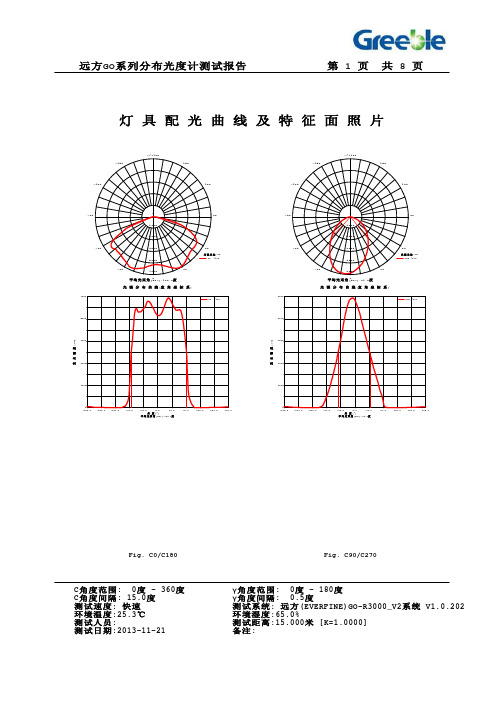
C135 C180 C225 5884 5806 5654 5957 5933 5524 6038 6217 5392 6081 6540 5271 5960 6846 5003 5605 6886 4701 5007 6696 4339 4368 6429 3877 3784 6209 3404 3326 6146 3002 2968 6179 2693 2611 6052 2379 2316 5475 2062 2057 4443 1723 1816 2907 915.1 1357 751.4 134.9 168.7 331.7 51.16 46.98 117.5 14.43 2.504 2.461 2.713 2.457 3.809 3.733 2.494 5.402 4.419 2.822 7.577 5.120 4.514 8.859 6.219 7.098 10.54 7.243 10.11 12.19 8.336 13.10 12.45 10.74 13.40 13.29 11.20 15.11 14.26 12.35 17.51 15.42 13.91 19.59 15.12 17.84 21.28 15.17 20.44 24.88 20.58 23.62 34.11 27.21 29.81 48.81 36.08 37.05 51.20 40.58 40.12 39.38 42.55 43.04
C0 5986 6239 6452 6670 6704 6438 6261 6112 6041 6072 6225 5453 3946 1805 454.0 167.3 63.95 14.40 3.415 4.470 5.783 6.293 7.443 8.845 10.24 10.87 12.48 13.45 14.62 14.29 15.82 21.88 32.29 47.89 52.55 42.31
LuxenHo

Product Name: Contemporary Oval Cascading Bowls Resin Outdoor Fountain with LED LightsSKU #: WHF1762Thank you for purchasing this LuxenHöme product. This product has been manufactured with the highest standards of safety and quality.PLEASE READ ALL INSTRUCTIONS BEFORE ASSEMBLY.Unpack all parts from Styrofoam and bubble wrap inside the carton to ensure there are no missing or damaged parts. If any parts are missing or damaged, do not attempt to assemble or use the product.CARTON CONTENTS:Description QuantityFountain 1Pump 1Compatible Pumps for this fountain:Pump Model No.JR350/LEDJB350/LEDYH400/LEDTools required for assembly: No tools required assembly.ASSEMBLY INSTRUCTIONS:1. Unpack the contents of the box and check to make sure that all items are accounted for and in good condition.2. Remove the pump from the package and untie the power cord.3. Select a flat, level surface for the assembly and final location of your fountain.4. From the opening at the back of the fountain, insert the water supply tube into the pump outlet ①. Connect the pumpadapter cord to the LED cord and twist to tighten the connection ②. Place the pump upright in the back of the fountain opening.5. Connect the power cord to the transformer and twist to tighten ③.6. Add clean water into the reservoir. The water level should be approximately 30mm lower than the edge of the reservoir.Ensure the pump in your fountain is completely submerged in the water ④.7. Connect the power cord from the pump to a properly grounded, grounding type receptacle (GFCI) ⑤.8. If installed properly, water flow in the fountain will begin shortly.9. Adjust the flow rate (if applicable) to the maximum (+) position. If necessary, readjust the flow rate to the desired level(remember to always disconnect from the power source before handling the pump).10. Please do not use the electrical plug during wet weather conditions. Please note: On first use, there may be air in thepump. It may take several minutes until all the air escapes.Product Name: Contemporary Oval Cascading Bowls Resin Outdoor Fountain with LED Lights SKU #: WHF1762Note: The above diagram is for illustrative purposes only.Product Name: Contemporary Oval Cascading Bowls Resin Outdoor Fountain with LED LightsSKU #: WHF1762MAINTENANCE OF YOUR PUMP:•Keep the water clean – clean water will prolong the useful life of your pump.•Use a pre-filter on your pump if available.•Regular cleaning of the pump will be necessary depending upon the environment in which it is operated. Clean the pump when it is visibly soiled or when a noticeable drop in performance is detected. Failure to clean the pump will result in overheating of the pump and the voiding of the warranty!•Before cleaning, always disconnect the pump from the power source.•Disassemble the pump by removing the inlet screen & the impeller housing. Remove the impeller/rotor assembly by gently pulling on the impeller blades. Use a soft cloth or brush to clean the area inside of the pump where theimpeller/rotor assembly was. Clean the inlet screen, impeller housing & impeller in warm soapy water. Reassemble the pump and inspect for proper operation.MAINTENANCE OF YOUR FOUNTAIN:•Unplug the pump from electric power before servicing, cleaning, or moving.•Keep water clean - using clean water will reduce mineral deposits and improve water clarity.•Clean the fountain periodically to prevent mineral deposits and contamination. Use warm soapy water and a stiff brush for heavily stained surfaces. Do not use harsh chemicals as this will damage the finished surface and void the warranty.•Add clean water periodically to ensure that the pump is fully submersed in water.•Disconnect the power and empty the basin if the fountain will not be used for an extended time.•If installed outdoors and in a freeze-area of the country, ensure that all water is removed, and the unit is completely dry.This product is NOT to be operated below 41℉ (5℃) freeze damage may occur.Special Warnings and Cautions:CAUTION:•The pump has been evaluated for use with water only.•Do not use the pump in water exceeding 35ºC / 95ºF.•Do not use the pump in flammable liquids.•Do not use the pump for industrial purposes.•Do not use the pump in vehicles or on ships or aircraft or swimming pools.•Do not use the pump in location where special conditions prevail, such as the presence of a corrosive or explosive atmosphere (dust, vapor or gas).•Do not let the pump run dry. Pump must be completely submerged for proper operation and cooling.•Do not lift the pump by its power cord.•Keep the plug dry. Do not expose the plug to water or steam.•Before connecting to the power source, make sure that the pump is assembled and completely submerged in water.Product Name: Contemporary Oval Cascading Bowls Resin Outdoor Fountain with LED LightsSKU #: WHF1762•Check the water level regularly to ensure the pump is completely submerged during operation. The pump should be fully submerged during operation. Do not add water while operating the product. Always disconnect the pump from the power source before adding water.WARNINGS:•To reduce the risk of electric shock, connect only to a properly grounded, grounding type receptacle.•To reduce the risk of electric shock, use only on portable self-contained fountains no larger than 5 feet in any dimension. •Do not exceed the voltage shown on the pump.•Always disconnect the pump from the power source prior to beginning any maintenance or work on the pump or fountain.•Inspect the power cord for damage before installation and/or maintenance. Replace the entire pump if damage is found. •For pumps with a 3-prong, grounded type plug, do not remove the grounding pin from the plug on the power cord.TIPS AND TROUBLESHOOTING:1. Ensure that the pump’s flow control switch is set to maximum (+) before operating. Once the flow is established, thepump can be adjusted downward to the desired level.2. If the pump operates, but there is no flow, check to ensure the pump is fully submerged.3. If the pump operates, but there is no flow, check the supply tubing for kinks and correct.4. If the pump operates, but there is no flow, and if the pump is submerged and there are no kinks in the supply tubing, liftthe pump from the water. Remove supply tubing at pump outlet and clean tubing inside and out if necessary. Reset pump in water (outlet side up) and once water begins to flow, re-attach the supply tubing.。
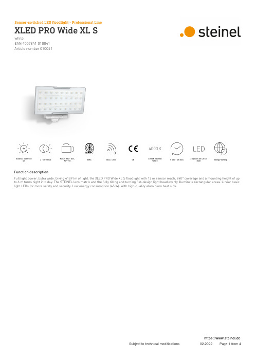
施耐德-xled pro wide xl s 户外led投光灯说明书
whiteEAN 4007841 010041Article number 010041manual override4h2 - 1000 luxPanel 360° hor.,90° ver.EMC max. 12 m CE4000K neutralwhite5 sec - 15 min30 years (Ø 4,5h /day)energy savingFunction descriptionFull light power. Extra wide. Giving 4189 lm of light, the XLED PRO Wide XL S floodlight with 12 m sensor reach, 240° coverage and a mounting height of up to 6 m turns night into day. The STEINEL lens matrix and the fully tilting and turning flat-design light head evenly illuminate rectangular areas. Linear basic light LEDs for more safety and security. Low energy consumption (45 W). With high-quality aluminium heat sink.whiteEAN 4007841 010041Article number 010041Technical specificationsDimensions (L x W x H)126 x 265 x 188 mm Mains power supply 220 – 240 V / 50 – 60 Hz Sensor Technology passive infrared Output 45 W Interconnection YesType of interconnection Sensor/slaveInterconnection, numbermaximum of 10 floodlights Vernetzung via: Connect Bluetooth MeshCable Lichtstrom Gesamtprodukt 3489 lm Gesamtprodukt Effizienz 78 lm/W Colour temperature 4000 K Colour variation LED SDCM3Colour Rendering Index 80-89With lamp Yes, STEINEL LED system LampLED cannot be replaced LED life expectancy (max. °C)50000 hDrop in luminous flux in accordancewith LM80L70B10BasewithoutLED cooling system Passive Thermo Control With motion detector Yes Detection angle 240 °Angle of aperture180 °Capability of masking out individualsegmentsYesElectronic scalabilityNoMechanical scalability NoReach, radial r = 5 m (52 m²)Reach, tangential r = 12 m (302 m²)Continuous light selectable, 4h Photo-cell controller Yes Twilight setting 2 – 1000 lx Time setting5 s – 15 Min.Basic light level function YesBasic light level function time 10 min, 30 min, all night Main light adjustable No Soft light start No Impact resistance IK03IP-rating IP54Protection class IAmbient temperature -20 – 40 °C Housing material Aluminium Cover materialPlastic, transparent Manufacturer's Warranty5 yearsEinstellungen via: Connect Bluetooth Mesh Remote control, Potentiometers,Smart Remote Installation site wall Cover material sticker Version whitePU1, EAN4007841010041whiteEAN 4007841 010041Article number 010041Detection ZoneDimension DrawingLight Distribution CurveOutput 45 WWith lamp Yes, STEINEL LED system Lamp LED cannot be replaced Luminous flux 4189 lm Colour temperature 4000 K Colour Rendering Index80-89LED life expectancy (max. °C)50000 hLED cooling systemPassive Thermo ControlMaster circuit diagramwhiteEAN 4007841 010041Article number 010041Master/slave and master/master interconnection circuit diagram。
Lux-Led-dv产品说明书
OPERATION INSTRUCTIONS Lux-Led-dvI.Safety information . . . . . . . . . . . . . . . . . . . . . . . . . . . . . . . .3 II.Features of the Lux-Led-dv . . . . . . . . . . . . . . . . . . . . . . . . .4 III.Set-up and operation . . . . . . . . . . . . . . . . . . . . . . . . . . . . .5 IV.Cleaning, maintenance and care . . . . . . . . . . . . . . . . . . . .8 VI.Available accessories, replacement parts . . . . . . . . . . . . .9 VII.Technical specification and connections . . . . . . . . . . . . .10 VIII.Troubleshooting . . . . . . . . . . . . . . . . . . . . . . . . . . . . . . . .11 VIII.Warranty information . . . . . . . . . . . . . . . . . . . . . . . . . . . .11To get the most out of your system, please read theseoperation instructions carefully before setting it up.Before using this product with your camera, please note the followinggeneral safety information.All persons installing, operating or servicing this product should familiarizethemselves with the following information:•It is mandatory to follow the instructions in this manual.•All users must be trained to work with this product.•The operation instructions form part of the product and should be handed over to any future owner in the event of sale/transfer of the product.•This manual should be retained for the life of the product.•If you have any questions about this product, please ask only authorized specialist personnel for advice.•Subsequent updates should be kept with this manual.Please note the following:•Use the device according to the specification only [see Technical specification].•The light must only be used when level! Operation in a vertical state does not correspond with the specification.•Do not bypass connections.•The casing may become hot. Caution: possible danger of burning!•Do not operate the light when the barn doors are closed.Caution: danger of overheating!•Ensure that the light is used at an adequate distance from combustible materials and that heat dissipates effectively.3•To avoid damage, allow the light to cool before packing it away.•Damaged cables must be replaced immediately by an authorizedservice provider.•Treat this product with care. Do not throw it or allow it to fall!•Do not immerse the system in water!• A slight odor may arise on the first use or if the system is usedfor a long time. This is normal and not dangerous.If you disregard this information, the system or your camera may incur damage!When using shoulder and handheld cameras, head lights are indispensable. The latest development from bebob is the Lux-Led-dv, a stepless focusable LED camera light.A completely new concept makes this light unique!With a sophisticated arrangement of five integrated LEDs, the illumination angle can be adjusted anywhere between 40° and 60°.At full modulation, the colortemperature is in the daylight range.The LEDs are now so efficient that the Lux-Led emits significantly more light than our conventional halogen lights, while consuming considerably less power.Thanks to its shockproof design and long service life, the light is ideal for newsreporting and outdoor sports.4The LUX-Led-dv is designed for mini HD/SD cameras [handheld camcorders; MiniDV, HDV, DVCPROHD]. It is however also suitable for all camcorders with a mounting attachment. Standard Lux-Led-dv package:•Lux-Led-dv [incl. connection cable]•Operation instructionsUnpack the parts supplied and check the delivery is complete.1. PREPARATIONAttach barn door system [optional]Attach the barn doors to the light with the filter levers upwards, push on and click into position with a right-turn. You will feel it lock into place. To remove, follow the same instructions in the reverse order.5III.SET-UPAND OPERATIONLux-Led-dv on Camera2. CONNECTING TO THE CAMERA Mounting options a)To attach to a male photo shoe, remove the slot nut.Slide the light forwards until its reaches the base of your camera and lock it with the knurled screw.b)To attach to a female photo shoe, screw the slot nut in loosely with the knurled screw.Slide the light forwards until its reaches the base of your camera and lock it with the knurled screw.Articulation allows the desired angle to be set.Please maintain an adequate distance from heat-sensitive materials.Power supplyConnect the D-Tap plug to a suitable power supply. The illustration shows an AB plug connection on a Sony camera as an example.Ensure that the cable does not touch parts of the light that become hot.6Lux-Led-dv on photo shoeLux-Led-dv [connection to D-Tap e.g. Coco orother voltage adapter]Switching onWhen the Lux-Led-dv is switched on using the switch on the underside of the light, it can be dimmed to any level with the dimmer.DimmerIf a head light is connected and the dimmer is switched on, the brightness is controlled by the dimmer wheel on the side of the Lux-Led-dv. Turning the dim-mer up will make the head light brighter,while turning the wheel downwards reduces the intensity of the light. At full modulation, the color tempera-ture is in the daylight range. Note: The color temperature changes when dimming.FocusWith the focus slide mechanism, the illumination angle can be adjusted anywhere between 40° and 60°.Please note:The flood position is optimized for applictaions with the diffusion filter!7III.Lux-Led-dv dimmerLux-Led-dv focusLux-Led-dv ON/OFF8Barn door systemTo avoid overheating, the light must never be operated when the barn doors are closed.The barn doors enable the illumination angle to be adjusted as desired.Caution: The barn doors may become hot during use!FilterThe 2-leaf barn doors come with an integrated diffuser as standard.The 4-leaf barn doors come with a diffuser and artificial light filter as standard.All system parts require zero maintenance.The casing must not be opened!A dry, lint-free cloth is recommended for cleaning.Do not use any cleaning agents.Damaged cables must be replaced immediately by an authorized service provider.The light may only be cleaned when cold.Check from time to time that the light is mounted correctly.If applicable, loose screws on the barn door or articulation system should be retightened carefully. Overtightening may damage the mechanism.Lux-Led-dv-ft [2-leaf barn doors]With the new voltage supply adapters, the light can be connected directly to all current models of the following manufacturers:•Canon [XH-A1, XH-G1]•Panasonic [DVX100, HVX200]•Sony [V1, Z1, FX1, FX7, PD170, VX2100]For these models, a camera-specific adapter and a 2-leaf barn door system is supplied. For JVC models and other ENG cameras, the light is available with a 4-leaf barn door system.Lux-Led-dv– by bebob9V.Canon Adapter Lux-Led-BPSony AdapterLux-Led-NPF Panasonic Adapter* Lux-Led-CGA Lux-Led-dvLux-Led-ft-dv2-leaf barn doorswith 1 diffuserLux-Led-ft4-leaf barn doorswith 1 diffuser and1 artificial light* für HVX200 und DVX100/ DVX100A DVX100B on request!Other accessories:LUX-LED-FT-DV2-leaf barn doors with 1 diffuserLUX-LED-FT4-leaf barn doors with 1 diffuserand 1 artificial light filter [3200K]Coco I-dvl Voltage transformer for Sony camerasCoco II-dvl Voltage transformer for Sony camerasBox VM Holder for Endura 7S batteriesFor prices and further accessories, visit www.bebob.de or call + 49[0]89/27818282Subject to technical change.Only use the light when level! Operation in a vertical state does not correspond with the specification.10The product does not include any parts requiring maintenance.If there is a problem, please check the following items first:If this does not solve the problem, please do not hesitate to contact us on + 49[0]89/27818282.In the event of damage caused by not following these operation instructions, incorrect set-up, incorrect handling or unauthorized interference, warranty claims are void. We assume no liability for injury to property or persons cau-sed by incorrect handling, or for consequential losses. For reasons of safety and conformity (CE), you are not permitted to modify and/or alter the light. In this case, warranty claims are void.VII.WARRANTY INFORMATIONLast updated 08/07© bebob GmbH 2007VIII.11。
莱维顿 DMX 灯光控制软件说明书
Leviton Mfg. Co., Inc. Lighting & Energy Solutions20497 SW Teton Avenue, Tualatin, OR 97062 1-800-736-6682 Tech Line: 1-800-959-6004 Fax: 503-404-5594 /les© 2013 Leviton Manufacturing Co., Inc. All rights reserved. Subject to change without notice.E n l i g h t e n L i g h t i n g C o n t r o l S o f t w a r eDESCRIPTIONEnlighten DMX lighting control software is specifically designed for house of worship and stage lighting control when the preference is for a PC-based computer running the Windows operating systems. Enlighten provides power and flexibility with an easy-to-use system that allows users to create unlimited buttons as looks or sequences. Program Enlighten to a PC or pair Enlighten with a control wing for unparalleled stage control.APPLICATIONS • Theaters• Convention centers • Ballrooms• Houses of worshipFEATURES• Multiple views to arrange fixtures graphically in different rooms or areas• Direct fader control with virtual wheel controls • Color coded button groups, allowing for multiple fixture types on a single page • Move any button to any position on-screen • Keyboard shortcuts • Password protection• Touch screen compatible• Expandable up to 24 universes (CPU and USB dependent)• Assign scene names to buttons for direct scene access • 3D visualization • GOBO visualizationSETUP• Patch fixtures from a list of available profiles or create your own • Auto start• Step by step wizard to create a look or sequence• Printable patch list • Offline editing• Live control override at any time • Backup and restore for entire shows • Full automated light support• Conventional lighting support; multiple views for conventional and intelligent lighting management• Lock look or sequence for house or ambient lighting• Full screen video can be played with lighting scenes• Adjustable DMX refresh rate • 3D studio import • Help featuresPLAYBACK• Effects generation• Unlimited playbacks and concurrent playbacks• Multiple masters • MP3, AVI, WAV syncEnlighten Lighting Control SoftwareEnlighten 512 Channel Splitter & USB InterfaceEnlighten Control WingEnlighten 512 Channel USB InterfacePRODUCT DATAEDITING FEATURES• Program looks at scenes step-by-step without the wizard with ease• Palette presets (foundation of the programming system; position presets)• Palettes automatically created on Patching or custom• Absolute and relative movement• Step-shift and shape-shift• Shape generator for movements with offsets • Shape library features an easy-to-use present effects lab• Macros• LED matrix engine and LED macros• MIDI, AVI, MPEG and WAV event sequencing and programming• Unlimited assignment of the following:- Fixtures- Buttons- Support fixtures- Button groups- Fixture groups• Unlimited pages of button triggers:- Still looks- Sequences- Multiple buttons- Timeline schedules• Spotlight mode: lock a button/look; once locked it cannot be released or overwritten • SOLO fixture modeINPUT/OUTPUT• DMX Outputs—up to 12,288 DMX channels • Ethernet—Artnet output• Optically isolated outputs• MIDI In/Output:- Assignable MIDI command for eachbutton and submaster for externalhardware control- MIDI input will trigger looks CONTROL WING• 8 high-quality sliders• 1 grand master• 1 manual crossfader• 11 job wheels for attributes and function control• 8 bump buttons• 32 assignable or preset direct access buttons with dry erase area• LED backlit button shows user interaction • Programming and playback function in one unit• USB <-> DMX Interface built in, 2 universe, 1024 channels• USB connector and LED indicatorSPLITTER• Enlighten DMX to USB interface built-in• Front and rear DMX input• 4 outputs• 3-pin and 5-pin XLR connectors on each output• Power and DMX status LEDs• Selectable DMX terminator• Rack or wall mountable• Opto isolated outputsE n l i g h t e n L i g h t i n g C o n t r o l S o f t w a r eLeviton Mfg. Co., Inc. Lighting & Energy Solutions20497 SW Teton Avenue, Tualatin, OR 97062 1-800-736-6682 Tech Line: 1-800-959-6004 Fax: 503-404-5594 /les© 2013 Leviton Manufacturing Co., Inc. All rights reserved. Subject to change without notice.SPECIFICATIONSPRODUCT DATAG-9005/C13-tbLeviton Manufacturing Co., Inc. Global Headquarters201 N. Service Rd. Melville, NY 11747-3138 • Tech Line: 1-800-824-3005 • Fax: 1-800-832-9538Leviton Manufacturing Co., Inc. Lighting & Energy Solutions20497 SW Teton Avenue, Tualatin, OR 97062 • Tel: 1-800-736-6682 • FAX: 503-404-5594 • Tech Line (6:00AM-4:00PM P.S.T. Mon-Fri): 1-800-959-6004Leviton Manufacturing of Canada, Ltd.165 Hymus Boulevard, Pointe Claire, Quebec H9R 1E9 • Telephone: 1-800-469-7890 • FAX: 1-800-563-1853Leviton S. de R.L. de C.V.Lago Tana 43, Mexico DF, Mexico CP 11290 • Tel. (+52) 55-5082-1040 • FAX: (+52) 5386-1797 • .mxVisit our Website at: /les© 2013 Leviton Manufacturing Co., Inc. All rights reserved. Subject to change without notice.ENLIGHTEN SCREENSHOTSAdd New Page Screen MFX SelectionMaster Fader Screen。
国光亮光绿色LED设备数据手册说明书
DESCRIPTIONThe Green source color devices are made with Gallium Phosphide Green Light Emitting DiodeFEATURESLow power consumptionPopular T-1 diameter package General purpose leads Reliable and ruggedLong life - solid state reliability Available on tape and reel RoHS compliantAPPLICATIONSStatus indicator IlluminatorSignage applicationsDecorative and entertainment lightingCommercial and residential architectural lightingPACKAGE DIMENSIONSWP710A10GDT-1 (3mm) Solid State LampNotes:1. All dimensions are in millimeters (inches).2. Tolerance is ±0.25(0.01") unless otherwise noted.3. Lead spacing is measured where the leads emerge from the package.4. The specifications, characteristics and technical data described in the datasheet are subject to change without prior notice.Notes:1. θ1/2 is the angle from optical centerline where the luminous intensity is 1/2 of the optical peak value.2. Luminous intensity / luminous flux: +/-15%.3. Luminous intensity value is traceable to CIE127-2007 standards.ParameterSymbol Value Unit Power Dissipation P D 62.5 mW Reverse Voltage V R 5 V Junction Temperature T j 110 °C Operating Temperature T op -40 To +85 °C Storage Temperature T stg -40 To +85°C DC Forward Current I F 25 mA Peak Forward CurrentI FM [1]140 mA Electrostatic Discharge Threshold (HBM) -8000 V Thermal Resistance (Junction / Ambient) R th JA [2] 680 °C/W Thermal Resistance (Junction / Solder point) R th JS [2]460°C/WLead Solder Temperature [3] 260°C For 3 Seconds Lead Solder Temperature [4]260°C For 5 SecondsABSOLUTE MAXIMUM RATINGS at T A =25°CELECTRICAL / OPTICAL CHARACTERISTICS at T A =25°CParameterSymbol Emitting ColorValue Unit Typ. Max. Wavelength at Peak Emission I F = 10mA λpeak Green 565 - nm Dominant Wavelength I F = 10mA λdom [1] Green 568 - nm Spectral Bandwidth at 50% Φ REL MAX I F = 10mA ∆λ Green 30 - nm CapacitanceC Green 15 - pF Forward Voltage I F = 10mA V F [2] Green 2 2.4 V Reverse Current (V R = 5V) I R Green - 10 µA Temperature Coefficient of λpeak I F = 10mA, -10°C ≤ T ≤ 85°C TC λpeak Green 0.1 - nm/°C Temperature Coefficient of λdom I F = 10mA, -10°C ≤ T ≤ 85°C TC λdom Green 0.06 - nm/°C Temperature Coefficient of V F I F = 10mA, -10°C ≤ T ≤ 85°CTC VGreen-2-mV/°CNotes:1. The dominant wavelength (λd) above is the setup value of the sorting machine. (Tolerance λd : ±1nm. )2. Forward voltage: ±0.1V.3. Wavelength value is traceable to CIE127-2007 standards.4. Excess driving current and / or operating temperature higher than recommended conditions may result in severe light degradation or premature failure.Notes:1. 1/10 Duty Cycle, 0.1ms Pulse Width.2. R t h JA ,R t h JS Results from mounting on PC board FR4 (pad size ≥ 16 mm 2 per pad).3. 2mm below package base.4. 5mm below package base.5. Relative humidity levels maintained between 40% and 60% in production area are recommended to avoid the build-up of static electricity – Ref JEDEC/JESD625-A and JEDEC/J-STD-033.TECHNICAL DATAGREENRECOMMENDED WAVE SOLDERING PROFILENotes:1. Recommend pre-heat temperature of 105°C or less (as measured with a thermocoupleattached to the LED pins) prior to immersion in the solder wave with a maximum solder bath temperature of 260°C2. Peak wave soldering temperature between 245°C ~ 255°C for 3 sec (5 sec max).3. Do not apply stress to the epoxy resin while the temperature is above 85°C.4. Fixtures should not incur stress on the component when mounting and during soldering process.5. SAC 305 solder alloy is recommended.6. No more than one wave soldering pass.PACKING & LABEL SPECIFICATIONSPRECAUTIONSStorage conditions1. Avoid continued exposure to the condensing moisture environment and keep the product away from rapid transitions in ambient temperature.2. LEDs should be stored with temperature ≤ 30°C and relative humidity < 60%.3. Product in the original sealed package is recommended to be assembled within 72 hours of opening. Product in opened package for more than a week should be baked for 30 (+10/-0) hours at 85 ~ 100°C.2. When soldering wires to the LED, each wire joint should be separately insulated with heat-shrink tube to prevent short-circuit contact. Do not bundle both wires in one heat shrink tube to avoid pinching the LED leads. Pinching stress on the LED leads may damage the internal structures and cause failure.3. Use stand-offs (Fig.1) or spacers (Fig.2) to securely position the LED above the PCB.4. Maintain a minimum of 3mm clearance between the base of the LED lens and the first lead bend (Fig. 3 ,Fig. 4).5. During lead forming, use tools or jigs to hold the leads securely so that the bending force will not be transmitted to the LED lens and its internal structures. Do not perform lead forming once the component has been mounted onto the PCB. (Fig. 5 )LED Mounting Method1. The lead pitch of the LED must match the pitch of the mounting holes on the PCB during component placement.Lead-forming may be required to insure the lead pitch matches the hole pitch.Refer to the figure below for proper lead forming procedures.Note 1-3: Do not route PCB trace in the contact area between the leadframe and the PCB to prevent short-circuits." ○" Correct mounting method " x " Incorrect mounting methodLead Forming Procedures1. Do not bend the leads more than twice. (Fig. 6 )2. During soldering, component covers and holders should leaveclearance to avoid placing damaging stress on the LED during soldering.(Fig. 7)3. The tip of the soldering iron should never touch the lens epoxy.4. Through-hole LEDs are incompatible with reflow soldering.5. If the LED will undergo multiple soldering passes or face otherprocesses where the part may be subjected to intense heat,please check with Kingbright for compatibility.PRECAUTIONARY NOTES1. The information included in this document reflects representative usage scenarios and is intended for technical reference only.2. The part number, type, and specifications mentioned in this document are subject to future change and improvement without notice. Before production usage customer should refer tothe latest datasheet for the updated specifications.3. When using the products referenced in this document, please make sure the product is being operated within the environmental and electrical limits specified in the datasheet. Ifcustomer usage exceeds the specified limits, Kingbright will not be responsible for any subsequent issues.4. The information in this document applies to typical usage in consumer electronics applications. If customer's application has special reliability requirements or have life-threateningliabilities, such as automotive or medical usage, please consult with Kingbright representative for further assistance.5. The contents and information of this document may not be reproduced or re-transmitted without permission by Kingbright.6. All design applications should refer to Kingbright application notes available at https:///ApplicationNotes。
500W PIR Halogen Floodlight 安装与操作说明书
SLB400G SLW400G NSLB150CeleCTRiCAl VOlTAGe230w inSTAllATiOn Helpline w1DiMenSiOnS - MMX:190 Y:250 Z:170XYZ WeATHeRpROOFip55DUSK TO DAWnADJUSTABlepRODUCTCOlOURBlackor manufacture, within 1 year of the date of purchase, please return it to yourw1pRODUCTCOlOURBlackor manufacture, within 1 year of the date of purchase, please return it to yourThe unit utilises passive infrared technology to detect heat radiation of moving human bodies. Upon detection, the lamp will illuminate for a user-determined time period.An integral daylight sensor ensures night-only operation if required.PaRtS INCLUded- luminaire c/w piR Sensor unit.- instruction manual. please keep safe for future reference.- Accessory pack.- Tungsten halogen bulb.tooLS & PaRtS Needed- electric/hand-held drill & bits.- Terminal or electricians screwdriver.- large slotted/philips screwdriver.- Wire cutters.Unit is for outdoor use only. Unit must be mounted on a non-flammable surface as a fixed luminaire, and is not suitable for portable use.The unit can get very hot during use. ensure the unit has cooled before handling.ensure adequate ventilation space is allowed between the unit and any object above, in front or to either side of the unit. Suggested space is 0.5m above, 0.3m to either side & 1.0m in front.if in any doubt, consult a qualified tradesperson or electrician.The motion detector has a number of detection zones, at various vertical and horizontalangles as shown (see diagram A).A moving human body needs to cross/enter one of these zones to activate the sensor. Thebest all-round coverage is achieved with the unit mounted at the optimum height of 2.5m.if the unit is mounted any higher than this, the sensor will need to be angled down slightlyto maintain coverage and forward coverage will be reduced.Careful positioning of the sensor will be required to ensure optimum performance.See diagram A detailing detection range and direction.The sensor is more sensitive to movement ACROSS its field of vision than to movementdirectly TOWARDS it (see diagram B). Therefore position the unit so that the sensor looksACROSS the likely approach path.Avoid positioning the sensor where there are any sources of heat in the detection area(extractor fans, tumble dryer exhausts etc.).Reflective surfaces (ie pools of water or white-painted walls) and overhanging branches maycause false activation under extreme conditions.CoNNeCtIoNpieRCe & pASS THe CABle THROUGH THe GROMMeT BeFORe pROCeeDinG.Connect the cable to the terminal block on the unit as follows (see connection diagram): neUTRAl (Blue)n eARTH (Green/Yellow)liVe (Brown)lensure that the connections are secure.For details of override connections, please see later sections.Secure the cable using the cord grip provided.line up the wiring box cover with the wiring box and press home ensuring that theCoNNeCtIoN dIagRaMMains SupplyisolationSwitch external WiringSlaveluminairesThe diagram below also shows the required connections for the addition of slave luminaires. When adding slaves, be sure not to exceed the maximum switchable load (see Technical Specifications).FWaLK teSt PRoCedUReThe sensor will rotate from left to right, and tilt forward or backward. Adjust the sensor to point in the required direction and angle down to limit forward range as required.the unit can be set up in daylight or at night.Set the time adjustment to minimum(fully anti-clockwise) and the light threshold to maximum (fully clockwise) see diagram C.Turn the power to the unit on. The lamp will illuminate for approximately 30 seconds. This indicates the unit is wired correctly.The unit is in Test Mode when the light turns off.teSt ModeThe lamp will now illuminate for approximately 5 seconds every time movement is detected.Walk across the detection area approximately 5 metres from the unit (see diagram B). each time you are detected the lamp will illuminate. now stand still until the lamp extinguishes (this should take approx. 5 seconds) and then for a further 2 seconds.Start moving again, when you are detected again, the lamp will illuminate.Repeat the above, walking at various angles and distances to the unit. This will help you to establish the detection pattern.if the detection area is too small for your requirements, try angling the sensor head up. This will increase the detection area. Angling the head downwards will reduce the detection area should a smaller coverage be required.SettINg UP FoR aUtoMatIC oPeRatIoNWhen walk tests are complete, the unit can be set up for Automatic Mode.The TiMe setting controls how long the unit remains illuminated following activation and after all motion ceases. (See diagram C, the time adjustment knob is indicated by the "Clock" symbol).The minimum time (fully anti-clockwise) is approx. 5 seconds, whilst the maximum time (fully clockwise) is approx. 5 minutes. Set the control to the desired setting between these limits.The DUSK control determines the level of darkness required for the unit to start operating. (See diagram C). The DUSK adjustment knob is indicated by the "Moon" and "Sun" symbols).Set the light threshold to maximum (fully clockwise/Sun end), then turn the control anti-clockwise about three quarters of the way round to the Moon end. This will give operation after DUSK approximately.For a more accurate setting of the DUSK control turn it fully anti-clockwise (Moon end) and leave for at least 20 seconds for the unit to settle.When the ambient light level reaches that required for DUSK adjust the DUSK control a small amount clockwise pausing to try to get the unit to detect and turn the lights under control On by moving a hand slowly backwards and forwards across the front of the detector lens for around 5 seconds.lesssensitiveMore sensitiveTOp VieW180ºSiDe VieW aCBdlens MaskRestrict long detection Restrict short detectionRestrict RHS detection Restrict lHS detectionMaSKINg tHe SeNSoR LeNSTo restrict the sensor coverage, preventing detection in unwanted areas, mask the sensor lens using the masking label provided (see diagram D). The top section of the lens covers long range detection, the bottom covers short range. Similarly the left and right lens sections cover the left and right detection areas respectively.MaNUaL oVeRRIde ModeThe light can be switched on for longer time periods by use of the Manual Override Mode. This can be activated at night by using the internal wall switch or circuit breaker.Switch the internal wall switch/circuit breaker once (off/on) within one second. The unit will light level SensorDusk level AdjustDelay Time Adjust12m2.5mBOTTOM VieWPRoBLeM❏ lamp stays On all the time night and day.❏ lamp stays On all the time at night, or piR keeps activating at random for no apparrent reason.❏ piR keeps activating for no reason / at random.❏ piR sensor will not operateat all.❏ The piR sensor will not operate at night.❏ Unit activates during the daytime.❏ piR coverage is poor/sporadic.SoLUtIoNCheck wiring connections. Wires to l and l1 terminals may be transposed.The unit may be suffering from false activation. Cover the sensor lens completely with black pvc tape. This will prevent the sensor from "seeing" anything. if the unit now switches off after the set time duration and does not re-activate, this indicates that the problem was caused by false activation. The problem may be solved by slightly adjusting the direction/ angle of the sensor head (see previous section). if however, the unit continues to remain On or to operate randomly the unit is faulty and should be replaced.You may not be allowing the unit time to complete it's warm-up period. Stand well out of the detection range and wait (the warm-up period should never exceed 5 minutes). Occasionally, winds may activate the sensor. Sometimes passages between buildings etc. can cause a "wind tunnel" effect.ensure the unit is not positioned so as to allow detection of cars/people using public thoroughfares adjacent to your property.ensure that the unit is mounted securely, even the slightest movement can result in a false detection.Check that the power is switched On at the circuit breaker/ internal wall switch.Turn OFF the power to the unit and check the wiring connections as per the diagram (see previous section 3). ensure no connections are loose.Check the bulb. if the bulb has failed, replace (do not hold bulb directly with fingers, use a tissue or clean dry cloth). ensure that the bulb is seated correctly in the bulbholder. Refer to section 4 for DUSK control adjustment.Refer to section 4 for DUSK control adjustment.Unit may be poorly located. See previous section - ‘Selecting The location’ and re-locate the unit.piR sensors are influenced by climatic conditions. The colderIn the event of the cover glass shattering, do not replace with normal household glass.Contact the helpline for replacement details.*The lamp supplied is a class C (high efficiency) unit of 100W powerconsumption giving a similar lightoutput to the lower efficiency 150W units previously in use.is a class C (high efficiency) unit of 400W powerconsumption giving a similar lightoutput to the lower efficiency 500W units previously in use.Helpline020-8450-0515*****************************For a product brochure please contact:Timeguard Ltd.Victory park, 400 edgware Road, london nW2 6nD Tel: 020-8452-1112************************For assistance with the product please contact:-67-058-302 (iss.2)SLB400G SLW400G NSLB150C。
- 1、下载文档前请自行甄别文档内容的完整性,平台不提供额外的编辑、内容补充、找答案等附加服务。
- 2、"仅部分预览"的文档,不可在线预览部分如存在完整性等问题,可反馈申请退款(可完整预览的文档不适用该条件!)。
- 3、如文档侵犯您的权益,请联系客服反馈,我们会尽快为您处理(人工客服工作时间:9:00-18:30)。
LED FLOOD LIGHT SERIES
250W LED FLOOD LIGHT
Product Manual
Ⅰ. I ntroduction
Materials
Patented fin aluminium heatsink structure; High quality aluminium processing technique; Special surface treatment process; High brightness LED light source, high efficiency and long life power supply.
Applications
Suitable for Warehouses, Production and logistics workshops, Retail stores, Theme restaurants, Amusement parks, Indoor stadiums and public places, and other industrial and commercial lighting purposes.
Features
* Unique patented thermal management design to ensure low LED junction temperature. * Extremely light weight for safety use and installation.
* Ultra high power to give ultra high brightness.
* Easy installation and maintenance, dust prevention, longer lifetime with high lumen maintenance.
* Energy savings, no UV and IR radiations, emits low heat.
Structure
* Unique fin aluminium heatsink greatly reduce product weight and guarantee the safety usage, as well as to avoid the material wastage comparing with conventional die-cast or extrusion heatsinks.
* By increasing the number of fins to enlarge the area of heat dissipation and air flow, this new heatsink significantly increase the efficiency of thermal conduction with less material usage and more saving on energy. It is the best solution of LED flood lights.
Ⅱ.Specification
1、250W LED Flood Light Main Parameters:
Remark :The light parameters may different between different color temperature, tolerances ≤ 5%.
Input V oltage 90-305 V AC, 50/60 Hz
LED Light Source Philips Lumileds (LUXEON Rebel ) or LG LED Qty 120 pcs LED Power 250W Total System Power 280W Led Luminous Efficiency 110-130 lm /W Led Initial Luminous Flux
23700 Lm 6M
351 lux 8M 156 lux Average Illuminance (85o x135o lens)
10M 87 lux 6M
7.3x19.3M 8M 10.9x28.9M Illuminance Area (85o x135o lens) 10M
14.6x38.6M Illuminance Uniformity >0.8
Color Temperature 4000K-7000K Color Rendering Index Typ. 70
Light Distribution Asymmetric / rectangular Illuminance Design LED+Lens LED Junction Temperature ≤70℃ (@ Ta=25℃) Working Temperature -40℃ ~ 45℃
Storage Temperature -40℃ ~ +65℃(Best 25℃) IP Rating IP65 Net weight 8.5 Kg Life-span >50000H
Power Cord
0.75mm 2 triple shield wire Brown
L live Blue N Neutral Connecting Wire
Yellow/Green
G Earth
Certificate CE ; RoHS ; UL (Power supply only) Light Fixture Color
Black
2、Product Dimension & Photometric Distribution:
Ⅲ.Installation Guideline
1. Take out the lamp from packing box.
2. Fix the light on mounting frame and keep stable placement. For safety, make sure the power cables are connected by electricians. The power cord is 0.75-1MM2 three-core cable wiring, the brown is live wire, blue is neutral wire, and yellow/green is earth wire.
Maintenance / Repairing Instructions:
1、Make sure the power has been turned off before maintenance or repairing.
2、Clean the glass cover regularly to maintain high transmission of light.
3、Clean up the dust from the glass cover and heatsink regularly to keep sound heat dispersion.
4、Be careful not to use water or corrosive solution for cleaning, preferably with a dry cloth.
5、When install or replace power supply, directly open the back cover with a screwdriver, then remove the power supply.
On DC power output, the red cable corresponds to the positive power polarity, and black corresponds to the negative. Pay attention do not reverse the positive and the negative in any circumstance.
Ⅳ. Package
1、Packing Size, weight.
Lamp packing size(W ,L,H) /1pc 570x450x180 mm
Lamp net weight 8.5 kg
Lamp gross weight (1pc/carton) 9.5 kg。