汽水取样装置技术规范书
(完整版)汽水取样装置技术规范书

汽水取样装置技术规范书目录附件1 技术规范 (1)附件2 供货范围 (16)附件4 交货进度 (19)附件5 监造、检验和性能验收试验 (20)附件6 价格表 (24)附件7 技术服务和设计联络 (30)附件8 分包与外购 (36)附件9 大(部)件运输 (37)附件1 技术规范1 总则1.1本技术条件适用于1x130t/h高温高压锅炉的全自动汽水取样装置,它提出设备的功能设计、结构、性能、安装和试验等方面的技术要求。
1.2需方在本技术协议书中提出了最低限度的技术要求,并未规定所有的技术要求和适用的标准,供方应提供一套满足本技术书和所列标准要求的高质量产品及其相应服务。
对国家有关安全、环保等强制性标准,必须满足其要求。
1.3供方执行本技术所列标准。
有矛盾时,按较高标准执行。
1.4合同生效后7日内,供方提出合同设备的设计,制造、检验、试验、装配、安装、调试、试运、验收、运行和维护等标准清单给需方,需方确认。
1.5在签订合同之后,需方有权提出因规范和规程发生变化或疏漏而产生的一些补充要求,双方共同商定。
1.6本技术书是产品订货合同的附件,与合同具有同等法律效力,在协议签订后,应互相按时交换资料,满足各方设计和制造进度的要求。
1.7本协议书,未尽事宜双方协商解决。
2 厂址条件及气象条件见建设单位提供的相关资料。
3、设计基础资料3.1 冷却水质水源:水处理室来补充除盐水水质:除盐水(若带闭式循环系统,冷却水为工业水)接口型式:平焊法兰,符合JB/T81-94标准,压力级:PN1.6MPa水压:1.2MPa( 工业水为0.5MPa)温度:≤32℃除盐水冷却水直接去除氧器。
3.2电源买方负责提供至每台低温架电源1路;提供微机系统电源一路。
电源电压:低温架:三相四线制(380/220V) 微机系统:220VAC UPS电源电源频率:50Hz3.3设备布置高温架、低温架室内分开布置。
3.4环境条件3.4.1环境温度高温架室:≤40℃低温架室:∽25℃3.4.2环境湿度相对湿度:76%4、技术要求4.1规定和标准4.1.1水汽集中取样分析装置验收应遵循DLT 665-2009《水汽集中取样分析装置验收导则》。
S-600汽水取样装置电气说明书讲解
目录机务部分使用说明一结构布置 (2)二保温处理 (2)三人性化的工作环境 (4)电气部分使用说明一配电装置 (6)二监控系统 (6)三主要技术指标 (14)四使用环境 (14)五保护原理 (14)六实现功能 (15)一结构布置S-600水汽取样装置采用箱体式拼装结构,高温高压、低温低压整合在一个箱体内但分布在不同的功能区域,由原来的高温架和仪表盘各布置在一个房间改为高温架和仪表盘合二为一,占地面积小,节约空间,整个箱体分为降温、恒温、人工取样、仪表电气四大功能区域,功能区域划分明显,全部采用正面操作的方式,在需操作的面上及检修通道入口处均为玻璃移门,可视性与可操作性强,外形美观;其布局示意图如下;图1 布局示意图二保温处理与以往的水汽取样装置相比,要实现高温高压和低温低压共处一室,必须要解决以下几个问题;1.为防止温度过高影响仪表的正常工作,在高温部分必须实现表面温度从600度降到50度以下,解决这一问题,我们采用二次隔热的方式,在高温区(即降温减压区)的样水进口管路进行一次表面降温,在管道外用隔热材料包扎使其温度降至50度左右,常用的隔热方式为硅酸铝纤维绳缠绕、硅酸盐复合抹面膏体涂料,陶瓷管等,其需保温的管路(图2)及保温方式(图3)如下;图2 需保温的部分图3 保温方式(以硅酸绳缠绕为例)2.高温高压与低温低压之间必须留有足够的检修通道,且通道内有适宜操作人员工作的环境。
检修通道的设计采用一端封闭,一端为通道入口的方式(如图1),连接管路全部在封闭端进行,通道入口端采用两扇玻璃移动门(如图4),既缩短了设备与墙体的距离,又保证了可视性,且外形美观。
图4 检修通道入口端在检修通道内部,经过上述的一次降温后,管路表面温度降至50度左右,而在高温高压的内侧,即检修通道内靠近高温高压侧的内壁采用可移动消音隔热层,材质可采用以泡材料或硅酸盐膏体涂料,这就是我们的二次隔热,经过二次隔热保温,使介质温度再次降低,以达到仪表工作温度的要求及操作人员适宜的工作环境,同时起到降低噪声的作用;而采用可移动门的方式,则保证了高温架及恒温装置背面的可检修性,便于维护。
S-600汽水取样装置电气说明书要点
目录机务部分使用说明一结构布置 (2)二保温处理 (2)三人性化的工作环境 (4)电气部分使用说明一配电装置 (6)二监控系统 (6)三主要技术指标 (14)四使用环境 (14)五保护原理 (14)六实现功能 (15)一结构布置S-600水汽取样装置采用箱体式拼装结构,高温高压、低温低压整合在一个箱体内但分布在不同的功能区域,由原来的高温架和仪表盘各布置在一个房间改为高温架和仪表盘合二为一,占地面积小,节约空间,整个箱体分为降温、恒温、人工取样、仪表电气四大功能区域,功能区域划分明显,全部采用正面操作的方式,在需操作的面上及检修通道入口处均为玻璃移门,可视性与可操作性强,外形美观;其布局示意图如下;图1 布局示意图二保温处理与以往的水汽取样装置相比,要实现高温高压和低温低压共处一室,必须要解决以下几个问题;1.为防止温度过高影响仪表的正常工作,在高温部分必须实现表面温度从600度降到50度以下,解决这一问题,我们采用二次隔热的方式,在高温区(即降温减压区)的样水进口管路进行一次表面降温,在管道外用隔热材料包扎使其温度降至50度左右,常用的隔热方式为硅酸铝纤维绳缠绕、硅酸盐复合抹面膏体涂料,陶瓷管等,其需保温的管路(图2)及保温方式(图3)如下;图2 需保温的部分图3 保温方式(以硅酸绳缠绕为例)2.高温高压与低温低压之间必须留有足够的检修通道,且通道内有适宜操作人员工作的环境。
检修通道的设计采用一端封闭,一端为通道入口的方式(如图1),连接管路全部在封闭端进行,通道入口端采用两扇玻璃移动门(如图4),既缩短了设备与墙体的距离,又保证了可视性,且外形美观。
图4 检修通道入口端在检修通道内部,经过上述的一次降温后,管路表面温度降至50度左右,而在高温高压的内侧,即检修通道内靠近高温高压侧的内壁采用可移动消音隔热层,材质可采用以泡材料或硅酸盐膏体涂料,这就是我们的二次隔热,经过二次隔热保温,使介质温度再次降低,以达到仪表工作温度的要求及操作人员适宜的工作环境,同时起到降低噪声的作用;而采用可移动门的方式,则保证了高温架及恒温装置背面的可检修性,便于维护。
汽水取样间管理制度
汽水取样间管理制度第一章总则第一条为规范汽水取样间的管理,加强对汽水产品质量的监督和控制,提高产品质量,保障消费者权益,制定本管理制度。
第二条本管理制度是制定的依据,适用于所有汽水取样间的管理工作。
第三条汽水取样间应当严格按照国家和地方有关法律法规、标准和规范的要求,保证取样过程的合理性和准确性。
第四条汽水取样间管理应当注重实践性和科学性,保证取样工作的公平、公正和公开。
第五条汽水取样间的管理工作应当严格按照本管理制度的要求执行,不得私自变更、违规操作。
第六条对取样间工作不认真负责或者违规操作的人员,将会受到相应的处理。
第七条汽水取样间管理应当依靠科学技术手段,不断提高取样质量和效率。
第八条汽水取样间管理工作应当注重团队协作和信息共享,建立健全的管理机制。
第二章取样人员管理第九条取样人员应当严格遵守国家和地方的相关法律法规,尊重科学精神,严格按照规定操作。
第十条取样人员应当具备相关专业知识和技能,通过培训和考核合格后方可上岗。
第十一条取样人员应当保持良好的工作态度,细心负责,不得怠慢工作,保证取样过程的准确性。
第十二条取样人员应当遵守工作纪律,不得因私利、私情等原因泄露商业秘密或者违规取样。
第十三条取样人员应当随时接受公司安排的监督检查,如发现问题应当积极主动整改。
第十四条取样人员应当严格遵守操作规程,保障取样过程的规范性和安全性。
第十五条取样人员应当积极参加培训和学习,不断提高专业素质和技能水平。
第十六条取样人员应当做好工作记录和档案管理,保留取样过程中的相关材料和资料备查。
第十七条取样人员应当遵守机密保密制度,不得将取样过程中获取的商业信息、技术资料等泄露给外部人员。
第十八条对工作不认真负责或者违规操作的取样人员,公司有权予以停职、辞退等处理。
第三章取样设备管理第十九条取样设备应当符合国家有关标准和规定,保证取样的科学性和准确性。
第二十条取样设备应当定期进行检测和维护,保持设备的正常运转和稳定性。
CXD汽水取样装置操作及常见故障的排除
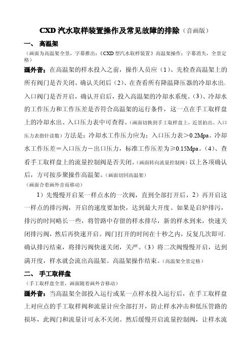
CXD汽水取样装置操作及常见故障的排除(音画版)一、高温架(画面为高温架全景,字幕推出:《CXD型汽水取样装置》高温架操作;字幕消失,全景定格)画外音;在高温架的样水投入之前,操作人员应(1)、先检查高温架上的所有阀门是否关闭。
确认关闭后(2)、在查看所有降温降压器的冷却水出、入口阀门是否开启,确认开启后,投入高温架的冷却水系统。
(3)、冷却水的工作压力和工作压差是否符合高温架的运行条件,这一点在手工取样盘上的冷却水出、入口压力表中可查得。
(画面切换到手工取样盘上,近景拍出、入口压力表指针读数)方法是;冷却水工作压力应为;入口压力表>0.2Mpa。
冷却水工作压差=入口压力-出口压力,标准工作压差为≥0.15Mpa。
(4)、查看手工取样盘上的流量控制阀是否关闭。
(画面转向流量控制阀)以上各项确认后,方可按步聚操作高温架。
(画面切回高温架)(画面合着画外音而移动)1)先慢慢开启某一样点水的一次阀,直到全部打开后,2)再开启这一样点的排污阀,开启的速度要加快,达到最大开度。
如果是启炉排污,排污的时间略长一些,将管路中存留的样水排尽,新的样水到来,快速关闭排污阀,然后再快速开启。
阀门打开的时间在十秒之内,反复几次即可。
确认排污结束,将排污阀快速关闭,关严。
(3)将二次阀慢慢开启,达到满开度,样水就会流出高温架。
高温架操作结束。
(高温架全景定格)二、手工取样盘(手工取样盘全景,画面随着画外音移动)画外音:当高温架全部投入运行或某一点样水投入运行后,在手工取样盘上对应点的手工取样阀和流量计应全部打开,防止样水冲击和低压管路的损坏,此阀门和流量计可永不关闭。
然后缓慢开启流量控制阀,让样水流出。
样水的流量取决于化学仪表的多少,在流量计上40~90为好,也就是说650~1500mmI/in。
电接点压力表入口处,接有冷却水失压保护装置。
当冷却水突然间断流,电接点压力表将接通保护,关闭高温架上的所有水样,防止设备的损坏和保证运行人员的安全。
汽水取样管理制度

汽水取样管理制度一、总则为规范公司汽水取样工作,确保取样过程的准确性和可靠性,提高取样质量,特制定本制度。
二、任务目标1. 确保汽水取样的准确性和可靠性,保证取样结果的真实性和客观性。
2. 规范取样流程,提高取样效率,提高取样质量。
三、适用范围本制度适用于公司汽水取样过程的管理工作。
四、取样责任1. 仓库管理员负责对汽水存储的定期检查,确保汽水质量的稳定性和准确性。
在仓库工作期间,对汽水存放位置和环境进行必要的维护和管理,确保汽水在存储期间不受到污染和变质。
2. 取样人员负责按照公司的取样标准和流程,准确、严格地进行汽水取样工作。
取样人员在取样过程中要保持专注,不得受到外界干扰,确保取样结果的准确性和可靠性。
五、取样标准1. 取样时间取样时间为每天的上午10点至12点,确保取样时汽水的质量和温度相对稳定。
2. 取样位置取样位置为汽水储存区,确保取样的汽水与存储的汽水相对应。
3. 取样工具取样工具为专用的汽水取样瓶,确保取样的准确性和符合相关规定。
六、取样流程1. 准备工作取样人员应提前15分钟到达取样位置,准备好取样工具和相关文件。
2. 开始取样按照公司规定的流程和标准,取样人员依次取样,并填写相关记录。
3. 取样结束取样结束后,取样人员将取样瓶放置在专用箱中,标注取样时间和位置,并送往实验室检测。
七、取样记录所有取样工作均要做好详细的记录,包括取样时间、地点、取样人员等信息,并在取样完成后及时归档存档。
八、取样检测取样结束后,取样瓶交由实验室进行检测,确保检测结果的准确性和可靠性。
九、取样结果处理1. 取样结果统计取样结果完成检测后,实验室将取样结果统计汇总,并反馈给相关部门。
2. 异常情况处理如发现取样结果异常,应立即通知仓库管理员和相关部门进行处理,并做好相应的记录。
十、违规处理对于违反本制度的人员,责任人将会受到相应的违规处理,严重者将承担相应的法律责任。
十一、制度宣传公司将定期对本制度进行宣传教育,使所有相关人员了解并遵守本制度。
水汽分析取样装置说明书(中文)
GRAND POWER水汽集中取样装置使用说明书型号:CXD吉林光大电力设备有限责任公司写在前面感谢您购买了由吉林市光大电力设备有限责任公司研制生产的CXD型水汽集中取样装置。
在设备安装、使用之前,请您一定仔细阅读说明书,严格按照说明书中的内容顺序和每一个具体步骤,熟悉如何正确安装、使用、维护设备,以便使设备能够很好地正常工作。
CXD型水汽集中取样装置以其理想的工作性能和操作简便、维护量小的突出优点、必将在您的专业工作中发挥巨大的作用。
伴随着您提高工作效率,CXD型水汽集中取样装置一定会成为您工作中不可缺少的得力助手,并为提高企业整体现代化自动控制水平作出她应有的贡献。
一、概述本装置用于热力设备水汽化学分析样品的预处理、人工取样、水汽品质的在线分析、被测参数的计算机监督管理。
本装置由三个基本部分组成:CXD系列化学分析取样架(通常所说的湿盘),完成样品的预处理、人工取样,为在线化学分析仪表提供合格的样品;分析仪表屏(通常所说的干盘),屏上安装在线化学分析仪表及记录显示器等;计算机管理系统,含数据采集、处理、显示、打印报表、监控、与上位计通讯等功能。
用户可以根据需要选定上述三部分中的部分或全部设备。
二、CXD系列化学分析取样架1.技术特点取样架采用全新的技术路线,获得了现有国内外取样架无法比拟的效益。
具体说来有如下特点:(1)取样架中采用了高温高压流体的高效降温降压器(专利产品),当高温高压流体(如水、汽等)流过该装置时,温度、压强同时降低,即具有传统取样架中冷却器和减压器二种功能。
(2)取样架没有减压器,杜绝了原取样架用减压器是最易堵塞,需要精心维护的弊病。
(3)样品流在高效降温降压器中的流动呈深度喘流状态,具有极高的热交换效率,在同样条件下冷却水的用量仅是现有冷却器1/2~2/3。
(4)样品流在高效降温降压器的管道中流速很高,对管道壁有自清洗作用。
(5)取样架中采用一种新颖过滤器――杆式过滤器(专利产品),仅截水样中1.4mm以上直径的机械杂质颗粒,基本不改变水样的组成。
水汽取样装置操作规程5
发电运行规程第五篇水汽取样装置操作规程第一节取样装置启动前的操作1.1降温架1.1.1 所有高压阀门应处于关闭状态。
1.1.2 所以各连接接头,紧固件不应有松动,脱落现象。
1.1.3 恒压装置压力调节螺母旋中位,出口调节阀处于关闭状态。
1.1.4 打开冷却水进出口母总阀,冷却水进口母管的压力应大于0.2Mpa。
1.2 人工取样盘和仪表盘1.2.1 检查所以阀门及部件连接处是否连接可靠。
1.2.2 人工取样盘上的限流阀应处于最大开度。
1.2.3 关闭仪表盘上的所以仪表取样阀门。
1.3 装置闭环保护系统1.3.1温控开关温控开关通电后输出闭合信号,保护装置应实施保护动作。
1.3.2 靶式流量控制器关闭冷却水进水阀或出水阀门, 靶式流量控制器应输出闭合信号,同时各样水保持装置应实施保护动作。
1.4 化学分析仪表仪表盘电气箱内电器元件齐全,接线端子连接可靠,分别接通各仪表电源,仪表接线正确。
-80-发电运行规程水汽取样装置操作规程第二节装置起动2.1 降温架2.1.1 依此开启冷却器的进出口球阀。
2.1.2 返冲过滤器置于“运行”状态。
2.1.3 逐路开启装置样水进口一次门和二次门(全开),打开排污门到最大开度,对各路样水逐路进行排污。
2.1.4 排污结束,关闭排污门.注: 关闭排污门前15S,将各返冲过滤器置于“返冲”状态,对滤芯进行返清洗,排污结束后将过滤器重新置于“运行”状态。
2.2 人工取样盘2.2.1开启人工取样盘样水门。
2.2.2调出人工取样流量。
2.3 仪表盘2.3.1 取出各仪表样水过滤器滤芯。
2.3.2 从各发送内取出电极。
2.3.3 开启仪表盘上各入口节流阀,对仪表样水管路进行冲洗,时间1分钟。
冲洗结束后,重新安装好样水过滤器滤芯和发送器电极。
2.3.4 全开恒压装置出口调节阀,根据每路样水所配仪表的数量,调节恒压装置调节螺母,使样水总流量符合要求。
注: 人工调节流量为500ml/min , DD 、PH表均为此300 ml/min , O2表500ml/min ,其它表计150ml/min。
汽水取样装置技术规范书
操作人员必须经过专业培训,具备相关操作技能和知识 操作过程中必须穿戴防护服、手套等防护用品 操作过程中必须遵守操作规程,不得擅自改变操作流程 操作过程中必须保持设备清洁,避免污染样品 操作过程中必须注意安全,避免发生安全事故 操作过程中必须做好记录,以便追溯和改进操作流程
汇报人:
取样装置:用于采集汽水 样品
传输系统:用于将样品传 输到分析仪器
分析仪器:用于分析汽水 样品的成分和性质
控制系统:用于控制取样 装置和传输系统的运行
安全防护系统:用于保障 操作人员的安全
辅助设备:如电源、冷却 系统等,为装置提供必要 的支持
PART TWO
取样装置应具备 良好的密封性能, 防止样品污染
PART FOUR
定期检查取样装置的密封 性,确保无泄漏
定期清洁取样装置,保持 清洁卫生
定期检查取样装置的电气 连接,确保安全可靠
定期检查取样装置的机械 部件,确保运行正常
定期检查:检查设备各部件是否正常工作 定期清洁:清洁设备表面和内部,保持清洁卫生 定期润滑:定期给设备各部件添加润滑油,保持润滑 定期更换:定期更换易损件,如过滤器、密封圈等
温度异常
检查取样装置是否正常工作,如有异常,及时更换或维修 检查取样管路是否堵塞,如有堵塞,及时清理或更换 检查取样泵是否正常工作,如有异常,及时维修或更换 检查取样系统是否正常工作,如有异常,及时维修或更换
PART SIX
操作前必须穿戴防护装备,如手套、护目镜等 避免直接接触取样装置,以防烫伤或割伤 确保取样装置处于良好工作状态,避免设备故障导致的安全事故 取样过程中,注意观察设备运行情况,如有异常及时停止操作并报告
,a click to unlimited possibilities
水汽分析取样装置说明书(英文)
GRAND POWERWater and Steam Integrated Sampling Unit INSTRUCTIONModel: CXDJILIN CITY GRAND POWER EQUIPMENT CO., LTD.I. SummaryThis unit is adapted to pre-treatment the sample of water and steam for chemical analysis of thermo-equipment, manual sampling, on-line quality analysis of water and steam, computer supervising of the checked parameters.This unit composes of three basic sections: CXD series Sampling Unit of Chemical analysis, which functions in pre-treatment, manual sampling, providing eligible sample for on-line chemical analysis; Analysis instrument screen, on which installs on-line chemical analysis instrument and record displayer etc.; Computer control system, which functions in data collection, treatment, display, reports print, supervising, and epigynous computer control communication etc.Clients can select part of the unit or select all according to demand.II. CXD series sampling unit of chemical analysis1. Technical characteristicUsing a total complete new techno-route, this unit acquires outstanding benefit that other sampling units cannot match, either domestic or overseas. In detail, the characteristics are as below:(1) The sampling unit adopts high-efficiency temperature-pressure reductor (with patent) for fluid of high-temperature and high-pressure. When fluid of high-temperature and high-pressure (such as water, steam etc.), flows along this unit, the temperature and pressure will be reduced, that is the unit works with double functions, one is as the cooler of traditional sampling unit, the other is as the reductor.(2) The sampling unit is not set with pressure-only reductor, which puts an end to the traditional disadvantage caused by reductor block resulted in too much maintenance.(3) The sample flows along the high-efficiency temperature-pressure reductor in a status of deep puffing, with high heat-exchange efficiency. Under the same condition, the usage of the cooling water is only 1/2 ~2/3 that of the existing cooler.(4) The sample flows along the pipes of the high-efficiency temperature-pressure reductor with speediness that helps the wall of pipes self-clean.(5) The sampling unit adopts a new-type filter, pole-style filter (with patent), barring mechanical impurity granule with diameter over 1.4mm without changing the composition of the water sample basically. Pole-style filter can self-clean for the large flux of the sample, block-proof, if need be, the exhaust drainage valve can be started to clean the filter. The pole-style filter is solid and durable, exempt from maintenance.(6) The sampling unit has a compact structure occupying little space, for example, ten-point of sampling unit is 2.5m long, 0.65m wide, and 1.6m high, every point of sampling added, only 0.2m longer needed, without changing of width and height, therefore, the occupying area is only 3/5 of the current sampling unit.2. Working conditions(1)Temperature of the environment:5~40℃(2)Power supply: 230V±10%,50Hz, 2KV A(3)Cooling water:A: Temperature: <35℃B: In/Out Pressure difference for cooling water in the temperature-pressure reductor: >0.2MPa C: Flux: subject to the number and the temperature of sampling points, fifteen points of sampling designed according to 30T/hD: The cooling water of the temperature-pressure reductor adopts de-salted water, without rot, dirt or pollute.3. Main technical index(1) Under the condition of the temperature not higher than 560℃and the pressure not bigger than 35Mpa, the temperature of the treated water is about that of the cooling water plus 5℃(±1℃), the pressure is smaller than 0.3Mpa.(2) The flux of water sample: ≥1500ml/min(3) Temperature of the outlet water can be set an alarming rating by the round detector by which the max absolute error measured should not be higher/lower than 1℃. Any exceeding of the alarm value will cause automatic alarming. The normal alarm is set at 40~50℃.(4) Pressure safety valve of the outlet water sample is set at 0.6~2.8Mpa, adjustable. Inlet of cooling water has pressure-overloading alarm, with lowest setting at 0.2MPa and highest setting at 0.8MPa.4. Formal dimensionsSeventeen-points sampling unit is 3.6m long, 0.65m wide and 1.60m high.5. Debugging procedure5.1. Preparation before operation5.1.1. According to the system diagram, be familiar with the positions and functions of all sections for the sampling unit.5.1.2. Regulate the pressure limits on the contacts of cooling water, and check the alarm system if normal.(1) Set the pressure meter on the contacts of the inlet cooling water pipe with a limit at 0.2MPa~0.8MPa.(2) Set the pressure meter on the contacts of the outlet cooling water pipe with a limit at 0MPa, and the pressure difference to the inlet not lower than 0.2MPa5.1.3. Power on the round detector, set the sampling cycle and alarm values according to Instruction settings.(1) Max. value of alarm is set at 40~45℃(2) Min. value of alarm is set at 0℃5.1.4. Check the nodes, airproof parts, fastening parts of the sampling unit if loosed, check the valves if closed.5.2. Pour in cooling water5.2.1. Open all in/out ball-valves at all points of sampling for cooling water5.2.2. Open the valves for in/out cooling water pipes. Pressure difference between inlet and outlet of cooling water pipes should not be lower than 0.2Mpa, as normal.5.2.3. Check the alarm(1) Regulate the inlet pressure on the contacts of cooling water at maximum (actual pressure of the cooling water, if alarmed, regard the alarm as normal. Then recover the pressure 0.8MPa.(2) Regulate the inlet pressure on the contacts of cooling water at minimum (actual pressure of the cooling water, if alarmed, regard the alarm as normal. Then recover the pressure 0.2MPa.(3) After finishes the alarm debugging, regulate the pressure difference between inlet and outlet at a stable status of 0.2MPa.5.3. Operation of high-temperature and high-pressure systemOnly if the cooling water works in normal condition, the high-temperature and high-pressure system can be operated.5.3.1. Manual sampling valve and the flowmeter knob are all opened5.3.2. Close first inlet and second inlet valves of sampling water, drainage valve and flow control valve.5.3.3. Slowly open the first inlet valve of the sampling unit, watch the connections of filter, the second inlet valve, contamination-drain valve to check if leaking, if leaks, fasten with special spanner (Be careful, work with gloves against scald).5.3.4. After the connections of the first inlet valve, contamination-drain valve and filter are confirmed no leakage, slowly open the contamination-drain valve to drain away the water in the pipe, with the temperature of water heighten to a stable point, fully open the contamination-drain valve then close immediately, repeat the operation of on and off for about three times, then close the valve.5.3.5. Slowly open the second inlet valve, watch the system of high-temperature and high pressure if leaking, if leaks, close the first inlet valve, repair the leakage, then open the second inlet valve. 5.3.6. Slowly open flux-control valve, watch the floater of the flowmeter rising, if the water sample flows smoothly, that will be considered normal.5.3.7. Regulate the flux-limit valve of manual sampling, make the flowmeter displaying a flux about 500ml/min, and regulate the instrument valve to let the instrument start working.5.4. Temperature overloading protection test for the electromagnetic valve5.4.1. Sizing down the inlet flux of the cooling water (smaller the opening of the valve), watch the display of the temperature round detector, when exceeds the alarm temperature, alarms, and at the same time the electromagnetic valve starts working to cut off the flow of the sample water, that certifies the normality of temperature overloading protection, then sizing up the inlet flux of cooling water (bigger the opening of the valve), recover the normal working status.5.4.2. Close the first valve, open the contamination-drain valve, the pressure of the water-flow system is reduced, open the water circuit which has been cut off by the replacement of the electromagnetic valve, then close the contamination-drain valve, open the first valve, recover the normal working status. When the decontamination system pressured, the above-mentioned operation could not open the electromagnetic valve. In case of that, close the flow-control valve on the manual sampling board, then go to the rear of the manual sampling board, loose the outlet running tie-in of the flow-control valve, discharging the air as well as the pressure, so then the electromagnetic valve will automatically open.5.5. Cooling water pressure reducing alarmDuring the operation, when the inlet pressure of cooling water lower than 0.2MPa, alarms, at the same time, the electromagnetic valve closes all its actions, cuts off the water circuit, when things happened like that, find the reasons then repair it(reasons, see the descriptions in the malfunction analysis column), the cooling water recovers the normal working status. If the electromagnetic valve does not action—not opened, do according to 5.4.2.5.6. Debugging of the safe valve5.6.1. The safe valve is set between the flux-control valve and the flowmeter, setting working pressure of 0.6MPa, acting pressure of 0.8MPa, when the flow circuit has overloading pressure, the safe valve automatically unloads. The safe valve is regulated well when leaving the factory, normally does not need regulating during the unit working. When it operates for a period of time or finds any malfunction, if need be, rechecks and regulates the safe valve as below:Connect pressure meters at the rear of the safe valve and between the connective pipes of the safe valve (range of 1MPa), close the water circuit to the instrument, regulate the manual sampling valve to raise the interior pressure of the sample water pipe to 0.6~0.8MPa. The safe valve starts to work, and be closed when the pressure lowers to 0.5~0.6MPa, then recover the normal working status. Otherwise, regulate the settings of the safe valve to the status above mentioned. Unload the pressure meter and install the safe valve.5.7. Operation StopFirst, close the first inlet valve of the sample water, then close the second inlet valve of the sample water and the contamination-drain valve, when the sample water stops flowing, close the inlet and outlet valve of cooling water, then close the power supply of the temperature detector.5.8. MaintenanceOpen the contamination-drain valve timely, according to 5.3.4. The period of contamination drain is subject to the purity of the sample water and the operational experience.〇Sampling point; Sampling point through ion exchange pole;side.Operating Rules for chemical analysis of CXD water and steam Sampling UnitI. PreparationBefore operates, check the valves of all points if they are closed, such as first high-pressure valve, second high-pressure valve, high-pressure contamination-drain valve and manual flux-regulate valve on the panel; check the screws if they are loosed, such as that of the high-pressure contacts on the unit (pipe joints of first/second class on the temperature and pressure reductor), cooling water piping, if need be, fasten the loosed.II. Cooling waterBefore operates, let the cooling water into operation with required condition. Requirements of the cooling water as below:1. Inlet temperature of cooling water <35℃;2. In/out pressure difference of cooling water should be not lower than 0.2MPa, (lower than 0.1MPa is definitely forbidden), calculated as inlet pressure – outlet pressure (read from the pressure meters of inlet and outlet)3. Flux of cooling water should reach the required amount. If In/out pressure difference of cooling water is eligible, the flux is satisfying.4. After the normal working of the unit, the cooling water should not be stopped to prevent accident of persons and equipment. In order to prevent accident, clients should set a spare power supply for the temperature round detector, if need be, contact the manufacturer for detail information.III. Temperature round detector and electromagnetic valveAs powers on, the temperature round detector shows temperatures of all points, alarms when pressure-loss, alarms when temperature overloading, electromagnetic valve working and some other functions.IV. OperationAfter finishes the above items, the unit could be started, according the procedure as blow:1. Open the manual sampling valve, floater flowmeter valve on the panel of manual sampling to prevent the result of pressure increased of low-pressure piping, or leakage, damage of flow meter. Above two valves can be often kept opened even if the boiler is stopped working.2. Open and close the high-pressure valves(first valve, second valve, contamination-drain valve) on the sampling unit, that must be fully open and fully close to prevent the fluid of high-temperature and high-pressure flooded and damaging the needle of the valve. That is important, please remember.3. When operates the unit, slowly open the first high-pressure valves at all points till they are fully opened, then open the contamination-drain valve (fully open), drain all contamination in the pipes, the detail draining time subject to:1) Contamination drainage when boiler starts: drainage away all the cooling water in the pipes, till the temperature of the pipes rises, then close the drain valve in a short time.2) Contamination drainage during operation: after the drain valve is open for five to ten seconds, then close it in a short time, if the sample water is dirty, repeat the above operation for some times, ordinarily once to three times.After finishes the contamination drainage, slowly open the second high-pressure valve, let the sample water flow along the filter to the temperature and pressure reductor, watch the high-pressure joints and pipes checking if leak. Normality confirmed, open all the second valves. That is the operation end of the high-pressure section.Note: the flux-regulate valve before the manual sampling panel is also a high-pressure valve( the front is high-pressure, the rear is to the low-pressure pipes). Prohibit working the first or second valve as sample water flux-regulate valves, otherwise, result in the high-pressure valve in the status of half-closed, that will destroy the high-pressure valve without working normally.V. InstrumentStart instruments with required quantity of sample water. First, open instrument valves that samplewater of all circuits flows through to the instruments, when the sample water to the instrument too much or too less, regulate the flux-limit valves set in the circuit of the manual sampling. The flux-limit valve regulates down, the sample water in the instrument will be increased, otherwise, reduced.VI. Safe guarantee system1. Temperature overloading alarm: there is temperature-overloading alarm set in the temperaturedetection, when the sample water at an exceeding temperature, the detector utters a buzz alarming, and at the same time commands the electromagnetic valve closed, sample water cut off to guarantee the security.2. Pressure-loss alarm: when the cooling water dammed by accident, the pressure meter at contactswill make pressure-loss alarm, and at the same time commands the electromagnetic valve closed, sample water cut off to guarantee the security.3. Low-pressure safety valve: for some reason (sample water of the instrument used stopped with theflux-limit valve opened), the pressure of pipes increased, when exceeds the security value of 0.7MPa, the low-pressure safety valve automatically opened, drains, till the pressure recovered, closed automatically.VII. Notice1. Pour in the cooling water at first, guarantee the pressure and pressure difference as required(Instruction).2. Manual sampling valve: the flowmeter should be opened or often be opened, to prevent any littledamage.3. The electromagnetic valve works in accordance with the commands of temperature detection and pressure meter of contacts, if the sampling point without sample water, close the first high-pressure valve at once, then open the contamination-drain valve, unload the pressure in the temperature and pressure reductor, then close the contamination-drain valve, start the electromagnetic valve automatically (not working) to prevent damage due to overworking and overheated, find the reasons, recover the normal working status of cooling water, then reset another time high-pressure valve, make the unit(sampling unit) work.EXCURSUS:1.The specifications of ion exchange pole: Ф51x4 mm H=800 mmV=1.161x10⁻³ m3=1.16 L2.Filling strong positive resin: Dool large pores positive acidic resin strong.GRAND POWER 光大电力GRAND POWER 光大电力Explore the cooperation and make friends all over the worldJilin Mengyou Tech •Grand Power Equipment Co., Ltd. reserves the right of amendment Address: Mengyou Technological Industry Park, Jilin High and New Technological Industrial Development ZoneP.C.:132013Tel. 86 432 4674552 Fax: 86 432 4683867 email:******************。