TUBEMICPRE电子管话放线路
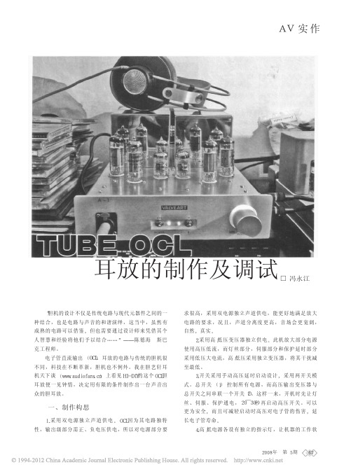
TUBEOCL耳放的制作及调试
为安全起见, 先在只通电伺服的前提 下, 测试伺服的“地”与主电路的 “地”之间不存在或轻微存在直流电压 差的情况下, 才能将伺服接入主电路。
2. 伺服 和 栅 压 电 位 可 调 不 能 同 时 使 用!
3. 在安 装 精 密 电 位 器 前 , 将 其 中 间 的脚调至电阻的中点, 尽量避免出现损 失。懂得原理的话, 更可将中点设得更 准确。
4.高/低电源各设有独立的指示灯, 让机器的工作状
2008 年 第 5 期 67
态一目了然, 使用过程更为安全放心。 5. 空 间 布 局 更 需 合 理 , 让 引 线 尽 量
短, 布线尽量将干扰降至最少。低压大 电流的线尽量贴近机箱, 高压线尽量架 空 。OCL电 路 较 为 复 杂 , 电 压 级 数 也 多 , 这点需要特别注意!
如 图1 , RCA输 入 端 子 就 近 设 在 电 位 器旁, 以降低对音质的不良影响。
图2为本机内部图, 空间的布局需十 分细心, 共8块PCB板装满机箱。
二、工作点选取
根据1 2AX7的曲线特性图得知 , 要取 得较低的失真, 除了采用一定限度的负 反馈外, 工 作点 至 关 重 要 。Ra= 1 00kΩ, 决 定 选 取 Ua = 300V, Eg = - 1 .5V, 实 际 上 , 现 在 的1 2AX7最高 屏 压 达 到350V! 而 此 静 态 工 作 点 Ea= 1 92V, 考 虑 到 放 大 系 数, 动态下, Ea还是小于Ua。
图4 为 曙 光 代 工 的 创 世1 2AX7和 俄 国 SOVTEK代工的EH EL84。
图 1 RCA 输入端子就近设在电位器旁, 以降低对音质的不良影响 图 2 本机内部图, 空间的布局需十分细心, 共 8 块 PCB 板装满机箱
AC-AUDIO TUBE G31单通道电子管话筒放大器 压缩器 说明书

CONTENTS1.OVERVIEW (1)2.BEFORE YOU START (2)- 2.1 Utilizing the User Manual (2)- 2.2 Safety Precautions (2)- 2.3 FIG 1: FRONT PANEL (2)- 2.4 FIG 2: REAR PANEL (2)3.INSTALLATION (3)- 3.1 AC Mains Supply (3)- 3.2 Microphone Input (3)- 3.3 Line Inputs. (3)- 3.4 Instrument Inputs (4)- 3.5 Balanced Line Outputs. (4)- 3.6 Unbalanced Line Outputs (4)- 3.7 Nominal Operating Level (5)4.GETTING STARTED (5)- 4.1 Connections in the recording process (5)- 4.2 In Use. (7)5.OPERATION (8)- 5.1 Compression Introduction (8)- 5.2 Input Source Selection (8)- 5.3 Mic Gain (8)- 5.4 Input Gain. (9)- 5.5 90 Hz Low Cut Filter (9)- 5.6 Drive and Peak LEDs (9)- 5.7 Threshold (10)- 5.8 Ratio. (10)- 5.9 Attack and Release. (10)- 5.10 Gain Make Up (11)- 5.11 Knee. (11)- 5.12 Compressor On. (11)- 5.13 Output Gain (12)- 5.14 Meter. (12)- 5.15 Meter ‘+10dB’ (12)6.SERVICE (13)1. OVERVIEWWelcome to purchase the equipment by AC-audio!The equipment is a signal processor that utilizes both valve and transistor technology. The audio processing units of equipment can support high quality signal paths, produce the particular valve audio peculiarity by adopting low noise solid-state electronic components and perfect valve circuitry. It has the comprehensive and various functions on controlling sounds, offering users clear, exquisite and high-quality sound.There are a single balanced mic input and stereo line inputs/outputs on the rear panel, and stereo instrument inputs on the front panel. The two channels of the equipment work in ‘linked stereo’ mode, but a mono signal can be applied to channel 1 only, thus can offer the equipment equally powerful for both mono/stereo tracking and final stereo mix processing. A single illuminated VU meter monitors the both channels for output level or the compressor gain reduction.To satisfy the requirement of performance that low noise, low distortion and wide bandwidth should be needed, electronically balanced input amplifier appeared. The preamp stage utilizes 48V phantom power and a high pass 90Hz filter. A Drive LED gives a visual indication of the signal level through valve stages, monitors the amount of ‘warming’ taking place. The Peak LED warns that overloading is going to be happened.The Mic input of equipment is provided on an electronically balanced XLR connector, and the line inputs are provided on balanced TRS stereo 0.25” jack connectors. Balanced and unbalanced line outputs can be used at the same time, and they are provided (again on TRS 0.25” jack connectors). The operating level of both the line input and outputs can be shifted from -10dB to +4dB via a rear panel switch, allowing the equipment to integrate into any system easily. On the front panel, without the need for a separate DI box, a pair of high impedance instrument inputs allows keyboards, guitars and basses to feed into the equipment directly.2. BEFORE YOU START- 2.1 Utilizing the User Manuall Be sure to read the Safety Precautions before using the product.l Refer to the INSTALLATION when installing your product.l You can easily find any information you are looking for by the CONTENTS.l Using the SPECIFICATIONS, you can easily find detailed parameters of the product. l Please read this manual fully before installing or operating the equipment.- 2.2 Safety PrecautionsFor your security and to prevent damage, please read the following Safety instructions carefully.Warning:l This equipment must be earthed.l All mains wiring should be installed and checked by a qualified electrician with all power switched off.l Do not locate it where it will be subject to external heating.l Do not expose to rain or moisture, as this may present an electric shock hazard.l Ensure the correct operating voltage is indicated on the rear panel before connecting to the mains supply.l Never operate the unit with any cover removed.l Replace the fuse with the correct type and rating only.- 2.3 FIG 1: FRONT PANEL- 2.4 FIG 2: REAR PANEL3. INSTALLATION- 3.1 AC Mains Supply.The equipment is fitted with a 3-pin IEC connector which is approved internationally. A mating socket with power cord and mains plug is supplied. Before connecting the unit to the supply, check that the equipment is set for the correct mains voltage. The unit is set for 110-120V 60Hz or 220-240V 50Hz operation internally, and should only be changed by an authorized service centre.The mains fuse required is 20mm anti-surge, 315mA rated at 250V. Sometimes, if it is necessary to replace the fuse, please use the same type and rating only. The power consumption of the equipment is 30VA.Please note that attempted operation on the wrong voltage setting, or with an incorrect fuse, will invalidate the warranty.- 3.2 Microphone Input.The microphone input is a via 3 pin female XLR connector, compatible for balanced microphones. The single microphone input of the equipment is automatically routed to both channels of the unit.The mating connector should be wired appropriately as the following way:Balanced inputs:l Pin 1 = Ground (screen).l Pin 2 = Signal Phase (also known as “+” or “hot”).l Pin 3 = Signal Non-Phase (“-” or “cold”).- 3.3 Line Inputs.On the rear panel, every channel has a 3 pin TRS jack socket, which will accept balanced or unbalanced line inputs providing the mating plug is wired suitably:Balanced inputs:l Screen = Ground,l Tip = Signal Phase (“+” or “hot”),l Ring = Signal Non-Phase (“-” or “cold”).Unbalanced inputs:l Screen = Ground,l Tip = Signal Phase (“+” or “hot”),l Ring = Ground.The equipment utilizes good quality screened cable, particularly for microphone or low level sources, So that hum or noise cannot be picked up.If a mono source is only connected to line input 1, it will be routed to both channels of the equipment automatically.Refer to Figure 2 for rear panel connector identification.- 3.4 Instrument Inputs.On the front panel, each channel has a high impedance (1Mohm) 0.25” instrument jack socket (see Figure 1). A 2 pin (mono) jack plug is required, which should be wired as the following way:- Tip = Signal Phase (“+” or “hot”),- Screen = Ground.If a mono source is only connected to instrument input 1, it will be routed to both channels of the equipment automatically.- 3.5 Balanced Line Outputs.On the rear panel, the line outputs are via 3 pin TRS jack sockets and may be configured for balanced or unbalanced connection. Balanced operation is always preferable to maintain maximum headroom and signal to noise ratio, but can only be used if the following equipment is also capable of balanced operation:Balanced outputs:- Screen = Ground,- Tip = Signal Phase (“+” or “hot”),- Ring = Signal Non-Phase (“-” or “cold”).Unbalanced outputs:- Screen = Ground,- Tip = Signal Phase (“+” or “hot”),- Ring = Ground.- 3.6 Unbalanced Line Outputs.A dedicated unbalanced line output is provided for each channel, on a 0.25” mono jack socket.- Tip = Signal Phase (“+” or “hot”).- Screen = Ground.These outputs may be used to the balanced line outputs simultaneously, and are useful for monitoring purposes particularly in a computer based system where latency free monitoring is necessary.- 3.7 Nominal Operating Level.A switch on the rear panel allows the line inputs and outputs to be matched to equipment at a nominal operating level of +4dBu or -10dBu. Most professional equipment requires +4dBu (approximately 1.2V rms), but some small mixing consoles or portable tape recorders require -10dBu (approximately 225mV rms). If the operating level is not known, the switch should be set to the position which results in the best signal to noise ratio, whilst preserving sufficient headroom.4. GETTING STARTED- 4.1 Connections in the recording process.There are many ways to connect the equipment:1) Connected ahead of the line inputs of a mixing desk/recording device2) Connected to a channel, group or master insert point1) Because of the various functions of the equipment, such as a mic preamp, line level or instrument front end, you can connect the output(s) of the equipment directly to the line input of your console, recorder or sound card. We do not suggest you to connect line level outputs to microphone inputs, because this may affect the quality of signal and may cause level overload on the mixer. The equipment has balanced line outputs for professional sound quality, but can connect to an unbalanced line input easily. Once the outputs are connected, feed your chosen source into the relevant input of the equipment simply (mic will connect to the XLR input on rear panel, line level signals such as mixer or tape machine outputs will connect to the equipment line inputs, and keyboards, guitars and basses will use the equipment front panel instrument inputs).The input selector switch is at the top left of the equipment front panel. Through it, you can select the relevant input source. ‘Mic 48V’ is necessary for condenser type microphones that require 48V phantom power. When using dynamic and ribbon type microphones the ‘Mic’ position only should be selected. Take care not to select the Mic 48V position when using such microphones as the 48 Volt feed could harm the microphone probably. The equipment will route the microphone signal to both the left and right output channels. If a mono instrument (or mono line level source) is connected to the left input (marked 1/mono) the signal will be routed to both left and right channels. Connecting a mono signal to the right input will send the signal to the right hand output only. Nowadays, it is a common technique recording direct to the multitrack recorder (thus bypassing the console), it can keep the signal path shorter, and get the highest quality.2) Insert points allow processors such as dynamics devices and EQs to be patchedin-line into the mixer signal path. Insert points are generally provided on a single TRS stereo jack socket, wired so that one of the pins is a ‘send’, one is a ‘return’ and the third pin is the earth. A special cable (called an ‘insert’ or ‘Y’ cable) is required to then patch in and out of the equipment – this cable will have a stereo jack at one end (the end that connects to the mixer) and two mono jacks at the other end (the end that connects to the equipment). Of the two mono jacks, one will be a ‘send’ that connects to the equipment line input, and the other will be a ‘return’ that connects to the equipment line output. This way the signal path is routed out of the mixer, through the equipment and back again, and this is a whole signal path.After the preamp stage, the channel insert point routes the channel signal out and then directly back into the desk. This insert point send/return facility is usually before the EQ section on the desk (‘pre EQ’), but some mixers allow for optional pre or post EQ insert points. They both send and return signals from the mixer but are different in application essentially. The auxiliary sends will split the channel signal, allowing it pass through the channel unaffected as well as being fed out to an effects device, allowing the original and processed signals to be mixed together to taste. This method is designed for processes such as reverb, echo and modulation effects.Insert points is typical to patch in dynamics processors/EQs rather than effects processors. It is because the entire channel signal would need to be processed by a compressor/EQ and then returned back to the mixer, thus ensuring that the whole signal is processed.Group insert points are used to compress sub-grouped signals. It’s common for an engineer to mix an entire drum kit or a number of tracks of backing vocals to a stereo group and then use a pair of group faders to control their overall level. In this way, the engineer needn’t to adjust each individual drum level. If you wish to compress the overall stereo kit signal, you can connect the equipment to the relevant group insert points, using the same ‘send and return’ technique as the channel insert.You can compress individual tracks when recording. It’s common to apply compression to the stereo mix while mastering it to 2-track tape, DAT or CD. Doing this will help you fatten the sound further and control levels. As the channel and groups, the stereo L/R mix buss will have a pair of insert points to facilitate this normally. If not, the equipment can be connected ‘in-line’ with the mixer’s main stereo outputs, ahead of the master 2-track recorder. Using master insert points allows the equipment to be monitored by the mixing desk’s control room outputs, but to monitor it when using it ‘in-line’ mode, it is normal to put the 2-track recorder in ‘record’ or ‘record ready’ mode, and have the outputs of the recorder feeding back into the 2-track return inputs of the mixer. A mixer usually has a2-track monitor option where you can listen to the output of the 2-track recorder.- 4.2 In Use.If you have connected the equipment, it’s time to use it. Here’s a simple step-by-step guide:1) Firstly, set up the gains of the unit. Start with the Input and Output Gains and GainMake-Up at 0dB, meanwhile the compressor switched out.2) Secondly, with the Meter set to read ‘Output’, adjust the Input Gain to achieve a peakreading of around 0VU with the chosen source material.3) If more output is required, you should then adjust the Output Level control accordingly.Now depress the Compressor ‘On’ switch, and depress the Meter switch to read‘Gain Reduction’.4) Now, the meter should register that some gain reduction is taking place. If not, or youwish more gain reduction to occur, increase the setting of the Input Gain control.5) You should notice that the output level is reduced when gain reduction is taking place.By toggling the Compressor On switch you can compare the levels and the subjective sound quality of the original and compressed signals. With the Compressor active, use the Gain Make-Up control to set the level so that when disabling the compressor, there is no level drop. In this way, You can distinguish the signals without the levels changing.6) Start with the Threshold at +10dB, Ratio at 1:3, Attack and Release at ‘Fast’, andKnee at ‘Soft’.7) Turn the Threshold clockwise towards -20dB gradually while continuing to meter gainreduction. When you do this you’ll notice that compression will start to take place and the meter will start to register some gain reduction. The further towards -20dB you move, the greater the gain reduction occurs.5. OPERATION- 5.1 Compression IntroductionCompression can replace manual control, it’s more sensitive and convenient. In addition, there are other benefits of compression that it can be applied properly. Adding punch and excitement to music is not the only benefit, it can also fatten up sounds and creating a more professional sounding recording. With the equipment, you have the added benefit of valve stages in the signal path, which create a warmth and presence. Valve compression yields a particularly special sound, it is popular to use in audio flied, particularly with the widespread use of digital products. The reason valve equipment sounds special is due to two things: natural compression and harmonic distortion. Valves will tend to naturally compress an audio signal, particularly as the signal level is increased. This itself contributes to the warmth produced by the equipment. Secondly, when the signal through a valve is increased, it tends to generate a particular type of subtle and desirable distortion, called “second harmonic” distortion. This has the effect of thickening and warming the sound, and the more the level you feed to the valve stages, the more of this harmonic distortion will be produced. You could hear this effect when you increase the Input Gain on the equipment.- 5.2 Input Source Selection.The input source and phantom power selection are controlled on a four position rotary switch. The selections are:MIC +48V: For condenser mics that require 48V phantom powerMIC: For most dynamic or ribbon micsLINE: Line inputsINST: Front panel Instrument inputsCAUTION: Please connect a microphone you need before phantom power applied. Do not connect or separate mic and equipment when phantom power applied. Furthermore, Adjust the Monitor/speaker for silent state before phantom power applied. Please wait for about one minute after phantom power applied, then regulate the output amplify, to ensure the system can be stable before this.- 5.3 Mic Gain.The Mic Gain control sets the level of the microphone input signal prior to the Input Gain control. There are 4-switched level positions: -20, 0, +20 and +40dB, with a further +/- 20dB available on the Input Gain control.For normal operation it is recommended to keep the Mic Gain setting at the +40dBposition, with any fine adjustments to the input signal level made by either boosting or reducing the Input Gain control. Keeping the Mic Gain at its maximum setting (+40dB) can help to keep the noise figures as low as possible. In extreme cases, high-level signal sources such as close-mic’d drums, it may be necessary to reduce the Mic Gain position to prevent input overload.- 5.4 Input Gain.The Input Gain control sets the level of the signal fed to the input stage of the compressor, and is variable between -20dB and +20dB. This allows a wide range of signals to be fed into the equipment, and also allows the valve stages to be driven to a variable degree. Each channel of the equipment has a triode valve stage positioned between the input circuit and the compression stage.Increasing the input gain pushes more signal level into the valve, thus generating more harmonic distortion and creating that special “valve sound”. At the same time the output level can be turned down to preserve the same level at the outputs, so a choice of sounds is available. For a more pronounced valve sound, turn up the input gain and reduce the output gain, and vice versa for a cleaner sound.Increasing the Input Gain control setting will tend to push the signal towards and possibly over the compression threshold setting, so this control will have a pronounced effect on the amount of compression taking place.- 5.5 90 Hz Low Cut Filter.The low cut (high pass) filter switch restricts the low frequency response of the preamp, to remove rumble or LF noise from the signal effectively. The filter is useful in restricting “popping” on vocals or even low frequencies caused by contact with microphone stands or microphone cables.Popping is an undesirable thump that is caused by close-miking certain spoken or sung letters, such as “P” or “B”. These particular letters cause a sudden expulsion of air that result in an audible thump. As this thump has a lot of low frequency content the high pass filter can help to reduce the problem, as using a bop cover suspended in front of the microphone. The 90Hz filter is active on mic, line and instrument inputs.- 5.6 Drive and Peak LEDs.The yellow Drive LED provides a visual indication of the signal level through the valve stages, and therefore the extent of “warming” or valve character being showed. The Drive LED will illuminate gradually when the input level or gain is increased, over the range 8dB to +18dB.The red Peak LED operates as a conventional warning that clipping is about to occur. The operating level of the entire signal chain is monitored, and the LED illuminates whenthere is less than 6dB of headroom remaining. Normal operation would be to set the input gain so that the Drive LED is illuminating regularly, with occasional lighting of the Peak LED on transients.- 5.7 Threshold.The equipment functions by reducing the gain of the signal when it rises above a certain level, known as the Threshold. Any signal below the threshold passes through the unit unaffected. The equipment has a variable Threshold control, adjustable between +10dBu and -20dBu.The Threshold control on the equipment starts at a ‘plus’ value in the counter-clockwise position, and decreases to a ‘minus’ value as you rotate the control clockwise. The reason for this is as you turn the Threshold control on the equipment clockwise then the degree of compression will increase.- 5.8 Ratio.Once the input signal has crossed the threshold, the degree of gain reduction is determined by the Ratio control. The Ratio control is calibrated in dBs and is simply the change in output level that results from a given change in input level. An uncompressed signal will have a 1:1 compression ratio - every 1dB change in input level results in the same 1dB change in output level. For instance, a compression ratio of 1:3 means that a 3dB change in input level will only give a 1dB change in output level. For more severe compression, turn up the Ratio control simply.The equipment offers a wide range of ratios from 1:1.5 (gentle compression) through to 1:30 (limiting). Limiting effectively clamps the input signal at the threshold level no matter how much the signal is increased: this can be useful when trying to ensure that the signal doesn’t exceed a certain level, for instance, to prevent a digital recorder distorting through overload.- 5.9 Attack and Release.The Attack and Release switches are used to control how fast the compressor reacts to the audio signal. The Attack switch governs how quickly the equipment acts to compress the signal once it has risen above the threshold, while the Release switch controls how quickly the signal returns to normal once it has dropped back below the threshold level.The Attack time of the equipment is switchable between 0.5mS (‘Fast’) and 5mS(‘Slow’). At 0.5mS attack, the compressor is fast enough to compress a 1kHz signal in less than half a cycle, effectively preventing the overload of any following equipment which has limited headroom, such as a digital processor, tape machine or transmitter. Fast attack times are used to compress a signal quickly, so are suitable for audio signals with sharpertransients such as drums. However, if you want the initial leading edge of the signal retained (for instance the initial click of a bass guitar or bass drum) then a slower attack time can be employed, and slow attack times can also be useful on sustained sounds like synth pads.The Release time of the equipment is switchable between 0.2S (‘Fast’) and 1.5S(‘Slow’). The Release setting is important, because if it is too short, the compressor gain recovers too quickly with the result that there is an audible ‘pumping’, ‘breathing’, and sometimes low frequency distortion. Try to use a slow release time in these cases.- 5.10 Gain Make Up.The Gain Make-Up control is positioned at the output of the compressor stage, and allows the signal level to be brought back to the same loudness as the uncompressed signal.While the subjective sound quality of the signal can be improved by compression, the overall signal level will be reduced when gain reduction is taking place. The Gain Make Up control is designed to boost the compressed signal by between 0 and +20dB, in order to bring back the level to the same loudness as the uncompressed signal. Without this control, comparing the original and compressed signals becomes difficult, since there would be a level drop each time the compressor is switched in: therefore it is normal to adjust the Gain Make Up control so that when the ‘compressor on’ switch is activated, the audio signal remains constant in level.The Gain Make Up control is different from the Output Level control. It can active only when the ‘compressor on’ switch is engaged. Once the Gain Make Up has been adjusted, use the Output Level control to set the overall output level of the equipment.- 5.11 Knee.The Knee switch controls the shape of the equipment compression curve. In “Soft Knee” mode, the response curve of the compressor around the threshold is gentle, so that the compression effect is more subtle and musical. In “Hard Knee” mode, the curve is more severe, so that signals above the threshold are “squashed” more aggressively. It causes the full compression ratio to be applied immediately the signal has passed the threshold point. This yields a more audible and pronounced compression effect.- 5.12 Compressor On.“Compressor On” enables or disables the compressor stage, thus allowing we making a comparison between the original untreated signal and the compressed signal. An associated status LED indicates when the compressor is active.- 5.13 Output Gain.This controls the level at the equipment outputs, and is variable between -∞ and +15dB. This control acts like an output fader effectively, and is very useful when recording direct to tape or hard disc through the equipment. You may find that some digital recorders require a good deal of input level in order to register a 0dB reading on their meters. This is normal, since many digital recorders are designed to preserve headroom and keep the signal well below the 0dB clip point - thus preventing the recorder distorting. The equipment provides ample gain to drive digital recorders, but you may find the Output Gain control has to be set to higher levels because of it.- 5.14 Meter.The equipment is equipped with an illuminated VU meter. The Meter switch enables the equipment’s VU meter to monitor one of two parameters. The normal mode allows the meter to read the audio output level, and is calibrated to read 0VU when a +4dBu signal is produced at the balanced line outputs of the equipment. Your dealer if required may adjust the reference point internally.Increasing the Output Level control on the equipment towards the +15dB setting will cause the equipment’s meter to move further towards the red area and possibly to the end of the scale if sufficient gain is applied.The meter may be switched to indicate the amount of compression occurring by selecting the ‘G/R’ setting. If the signal is below the threshold, the meter will indicate 0dB: i.e. no gain reduction. As the signal passes through the threshold, the meter will start to indicate the gain reduction at the compressor stage. Note that this reading won’t include any extra gain make-up applied.- 5.15 Meter ‘+10dB’.Sometimes the output level of the equipment may need to be set to a relatively high level, particularly when driving a digital recorder. The Meter ‘+10dB’ setting reduces the normal meter reading by 10dB so that high output levels can be generated without the VU needle pressing constantly at its end stop. This doesn’t affect the actual output level, but only the metered reading. This setting also has no effect when the G/R switch is engaged and the meter is reading the amount of gain reduction.6. SERVICEIf you want to require service of the equipment, you must take it or post it to an authorized dealer with a description of the fault. When claiming service under warranty, proof of purchase date must be included with the equipment for repair. Please retain the original packing for possible future use, and ensure that the unit is protected suitably during transit. The manufacturer cannot accept responsibility for damage caused during transportation.The equipment is supported by a limited warranty for a period of one year from the date of purchase. During this period, any faults due to defective materials or workmanship will be repaired free of charge. The warranty excludes damage caused by deliberate or accidental misuse, tampering, operation on the incorrect mains voltage, or without the correct type and value of fuse fitted. It is the user’s responsibility to ensure fitness for purpose in any particular application.The warranty is limited to the original purchase price of the equipment, and excludes any consequential damage or loss.Please record the following details, and retain proof of purchase:Serial Number................................................................................Region / Country............................................................................Date purchased.............................................................................. Dealer.............................................................................................User name...................................................................................... Tel................................................................................................... Address...........................................................................................。
电子管功放电路大全

电子管功放电路大全本贴图纸都经过实做验证,转载请注明出处。
6L6G(6P3P推挽1,输出功率25W THD=0.3%EL84(6P14)推挽,输出功率15W前级 1(12AX7+12AU7)Lin XU in. 1G0/3V4.71迁imvV4/V7Fl 再4ETB5CT/C1D卜 0血.mnyFT 翻B20 /I23WB0 6SKRir/Tr 'F=,制 1» R1/E2■=20I3LIK.K22 ^TOKCJ L/D12seouFEUd^TJl ^L.DLkai t i bv Jul a 6h hifidirCft/raF 「I -;T WO'/㈣3KLfb/'RflLin/Kir150KR3/R715KR2/R61.2K稳庄10u22K--RW5 150KL_10.1 u0.1 UJ-. C1/C2 厂。
眈4厂信号输入R1/R8IMR12R13/R1 7470K75tJ4-30CIVC5lOu*385/+R14/R1556K12/IU71U05)06豔XtRI9/R194 7Oik1DKR12R10/R11前级2(12AX7+6DJ8)Giro4K+30(VLin 信号/Kin辆天2KZIOKR5R4卜/R413.3K270KR2ZR2‘3"1$4压至rVI, V2^12AX7; V3=E36CC/6S2£C3/C3P4.TuFLout/RoutR9 4.70K lOufRIOIO皿EllLOOKCUD前级电源1b_別£A>5/-至灯竺L3.5Yi罟AC15)+30 JV -n(100^D1ci R547TIF111DOE酣DE,HET13斗TZIR4941(-EK PIiE04 TuJE6E> CWD*■-T^CBTHUOinnK4丁展rrtcE 不新增一张300B图纸HI —bJ ^3 hJ kJlFl W Fl Flg ⑧弩(MA o-cr^H-j i og420V 'O --斗El 宵单声道设计注:本图为单声道设计123GV100RJ DJB6FF0.Z2UIHH0_22U 4Q0V .I1200V10QK250K2CR A 22W2SF :1271HOCK►?niKI0J 6O0VHI ~r —> '1-1 r Hl IT” 12F47hEU4G6550单端图纸1(三极管接法),输出功率8W8R1507ov owpnfn5H 0.2SAhifidiy. net470ky 1K\i、卜D.33U2667EVW-10R40OV 0.35ASU4G410V91K300K退瑞曲单声道便用4_3KVW2D0V 350^ -50 中777伽400V ^Rck* 460V220V 50Hzcrc>it7O1380V*2o 02A27K------ :220u1E0VSAR4Y W10R1jLac5ev loon 1W3Wrmn0.25A5O0VK氓耦为单声道便用I电阴未柱:明皆妁1州灵敏度CU菇甲PQ=0W CTHD=0.4%)Po-1^CTHD-0.05%)net 纯真之源已改版实做,第二版各种功率管电路如下:6550/KT88单端,输出功率13.5Whi fidiy. net 3K■AMni>rP220U/16V49V0.47U160V35K1MEG+51 OK 36QV1|vtG C.33W■VW~―IF—■8R=■345V10R1OU400 VSV3A6.3 V 5A6,3 V1 ,5A5AR412K 2WVW->Rctl5H0.25A退耦芮单声道使用56V 91K1W *3 M1 ■ H r< / //^ I 215 V■zi22Cu45QV2 2加400Vhi fidiy. netni>rP1ME*5■vW±0.47uT16CN2K■AM220M/16V10R6.3V5AR422u400 V315 V 3.9Ki -------- vW"仍22SV3AS.3V SA °j&L6Ga埶ih1MEG+51 OK-VA/ ----< 24OK 150、5 5W *5H0.25A-107±6S0u2ff5D¥------------------ ——477 3.3K1W *3 MH T< ///M i 21 S'/45QV2 2加400V330V -^RciiSR—■2K ■AM--------------------------------- 1 • ------- AV ----------- ------------------EL34LK 45V 伽旳Q 卸1K(匸二二 ---------- 35K1MEG+51 OK330V-107Fa6SN7◎:>B6K470K77710R5AR42妙5H 0.25AS.3V SA 丄OMu"T160V<24OK 130 < 5 5W v235 屮 2&.25ASV3A±6S0uT SOY51510> 22EJW/15V22'A400 V3.9K <W6.3V—■ 8R=■34(JV47V47k1W 22W11H T < ///^ 121OVz ;£ 22Cu45QV2 2加400V6SN745V 伽冈a 埶S0713 5V<24OK:>B6K100 5W0.47U 160V2KAV ---------------------------------1MEG+51 OK曲 W---- -------- AV ----------- _-—235 屮 2 &.25A400 V6.3V强10R5AR4hi fidiy电阻除建明外』皆1吨1J 率5H 0.25A2 2加400Vz ;£ 22Cu45QV1W *3 2WiiH T < ///Mi 26CVSV3ASRT 1J >@ni>r P 22DU /16V3.9K *W*6S0uzffsov34(JV *—>Rcti2K■AM---------------------------------1•------ AV -------- ----------------二\ 45V伽旳KT66Q埶1K (匸二■——35K 1MEG+51 OK 330V17.5V2NV 6SN7<24OK:>B6K47OK1OR 3.9K*w-5H0.25AS.3V SA °j丄OMu"T160VSV3A51022CJM/15V400 V6.3V5AR4ir—■8R=■2205W±6S0uT SOY34(JV30V 2K1W *32WII H r< ///^'防[TV235 屮2 z;£ 22Cu45QV2 2加400VPG苦U一511ME*5■vW±0.47uT16CN&1461MEG+51 OK—■8R=■S 3V SA5€V11 OK1W *2 2WH r<—"vVJi 13SV324V11 ----3.9KVW-10R5H0.25A22U400^76 ,3V 1 .SAo*6S0uzff sov34(JV5AR4285 屮2025A45QV=f 2加400V电阻除建明外』皆1吨1J率hi fidiy- net6V6/6P6P 单端,输出功率4W3.3K ■AM6SN7©E10 、、220M /1 SVlOu 385V---------------------------------------- 1二X 羽甲 1MEQ D22U 1KC二 ________S1MEG+51 OK2fiSVRch12.5V7OK•—>Rch2K_LD.4TuT160V250 3WS.2K6S0u 50V口 SV 护2V¥VWT8RS.3V 5A °j 6 ,3V 1 ,5Acj5AR4235/2 0 15A10R电阻际注明外』瞥冈功率150U385V5H □ .15Ahi f idly.805单端图纸,输出功率大于25W15K1Mc丁50R750K85V 27k2pFO.33u75KT 192V V1" --------F5OW5W7KRRVI : EF06—| 1V300K430R*■1 UH/0.2A1 0R/5W6V 3AF 'F '丈图肯堆声道设计5K 3W750V0.2A1OPRJ<1 47K220K 2W24WO.25A220K2W 4- IB100uF 450V t -500VT贮Du 車500V10I O U ^—■ -- ■ -------D1 ~D6,FRl0rX-10J1OOV5H/O 2A230V470KD2D3-D65SV 500 R 19/Vit调节RX1憔工作点写压基奉符告厦中虹邑标示1OOUSDOV T4ilODuF450VT I ------------------y---- d ---- 1—i 15000UFA10WT010V 5A330u1BOV73:805AV4 : 5AR422QK2W A b910V22OK ZW3K7.5KDZ1300V1115UIF400VDZ1 I 51¥口理稳压二瀬苛E 支串底10K 2MEG2pF100K165V1.5V470K470kIOCo.33u1MEGS6VE20 占22lJu10V丁50RV276V7.5KF」‘ 5OW5W5SV 500 R19/Vit调节RX1憔工作点写压基奉符告厦中虹邑标示emo.2A1 0R/5W6V 3AD1~D6,FRlor6' F 'F '丈图肯堆声道设计10V 5A750V 0.2A10P220K 2W24W0.25A220K2W MOOuF 牴0V 500VT贮Du 車500V10I O U ^£O0V5H/0 2A22QK2W 920D2D3-D6330u 1B0V100USDOV T22OK ZW4ilODuF450VTl -----------------------J3CY +y ---- d---- I —i 15000UFA10WT00R900VVI:6SJ7 V2 ;EL3473:805AV4 : 5AR43K-i x A DZ1o - 30 c1DZ1 I 51¥口理稳压二瀬苛E 支串底811单端图纸,输出功率14WV1 .EF86240KV2.EL3450K —*11V2.911A 47 OKV4.5AR410H/0.2A10W5W550V-SSOV5lK0.1 uFi170VSDR2和1OOR冋JL5aR/10W 1 =" I 卜1K 15W100u 160 V220/23DV .^Ci.lS A供 EF8GEL844SOVD21OOu^3S5V1OR2W 申 WOuF450V------------11 -----------100U220K 2W6.3V6A0.1 R 1OW220K2W 330u4i 2I85V 330 U _3B5VD1 ~D6,FRl0r5H C.2Ae 1300715000UF 16V本團为单声道设讨:20K2W 22OK ZW1OK6BK■F330UF450V-A ------DZ1240VF' F'hiSun Audio 2A3单端改进版,增强全面性,平衡性,提高低频速度力度2A3推挽图纸,输出功率12W THD=0.24%700\'0.22LJ3UJH.4 7KJ4k350V1.6KTW 373YF-F1DLI1O(X27K2WS2K2WJ2U电谊退雜都分対单声道使用电阻际注明外皆3 3枫g j 220Li1C0V47u S!4iOV *H I51KJ+ 2000U—400V270V*20.3AI .Jfv3.5KVI-6SN70^2uV2-BSM773,74=2 A3hifidrmethifidiy. n&t。
电子管前级

和田茂氏电子管前置放大器由于电子管(俗称“胆”)在音质、音色上有着优异和独特的特色,另外也因为其电路较简单稳定,制作与调试都比晶体管机更方便,因此电子管在音响方面的应用近十年来又再兴起,特别是在业余土炮发烧圈里更是热度高涨。
电子管的Hi—Fi功放应用电路早在五六十年代就达到设计的高峰了,经过三四十年后,现在常见的应用电路和电子管基本上还没有什么改变,与当时的面貌相差无几,土炮发烧友如能自己选读自修一些有关于电子管理论常识,定能事半功倍。
电子管在音响应用方面,最简单而又最实用的地方莫过于用它作前级信号放大,因为前级无需要复杂和昂贵的输出变压器,这点比用作后级功放简单得多。
同时也由于它需要的工作电源电压高,放大倍数较大,即使放大到几十伏电压也不会因为电源电压限制而造成削波失真,在这方面就算是Hi-End级的晶体管前级也无法提供如此高的输出信号!笔者十年前因购买的CD音源是较早期的16bit机种,出于电子管能给尖利干硬的数码声增添音乐韵味、改善听感,也因电子管前级较易制作及回报率高,多年来也尝试制作过不同线路音效的多款电子管前级,当然也不是指望能研制出什么伟大经典线路,但最少也能享受制作的乐趣。
在电子管前级中,在50年代末推出的Marantz 7的地位可以称得上至高无上,现在玩电子管的发烧友中没有听过Marantz 7的大名者,相信已经没有多少人。
Marantz 7的主线路如图1所示,(本刊在1999年第2期有详细仿制文章。
)电路中,VRl、VR2用作电压放大,VR3接成阴极跟随器作为信号缓冲,VR3的作用相当于用NPN管连接的射随器。
Marantz 7电路最大特色就是整体环路反馈设计,这也是Marantz 7赖以成名的一个主要因素。
但由于Marantz 7输出端是接上一个三级阴——阴型负反馈网络,此网络高频高端阻抗约在20kf~以下,这显然太小了,这种设计无疑对VR3造成相当大负担。
另外,为了防止高频自激,Marantz 7在VRl和VR2之间接上一个22PF电容,构成高频局部负反馈,这种设计也降低高频放大倍数。
TUBE PREAMP 530 现代汽车音频系统用户手册说明书

professional quality tube sounds in a modern, exceptionally compact 19" rack-mountable package (1 rack space). The two main channels Clean and Lead feature dedicated voicing sections, gain pots and volume controls for precision sound shaping and fine-tuning. The Gain Lo/Hi switch converts the Clean channel to a Crunch channel and, in the Lead channel, the sound spectrum encompasses everything from Heavy Crunch to Ultra Gain. With a 4-band voicing section featuring two midrange bandwidths and ahandy feature is the Defeat function, which bypasses the preamp and routes the guitar signal directly to the output. This feature enables you to connect two preamps in series and this option enlarges the tonal spectrum. The variable Stereo Line Out and a frequency compensated Line O ut give you a wide range of application options, for instance you can patch the preamp signal directly to a mixing console or recording devicewhich is equipped with an impressive array of high-tech features that deliver a wide range of devastating sounds, come highly recommended. The integrated 2 x 1, 5 Watt stereo poweramp is suitable for three different applications:1, practicing with stereo headphones,2. practising with hi-fi stereo speakers, and3, practicing with a conventional guitar speaker cabinet.This preamp is defined by the effort and materials that went into it: intelligent design features, superior craftsmanship, impeccable finishing and quality components. However keep in mind, that a few precautions will radically extend tube life (see handling and care guidness).The entire-Team would like to thank you for your faith in ourproduct; we hope you derive a great deal of joy and satisfaction fromPLEASE NOTE: Read the O perator's Manual carefully and thoroughly, especially the Handling and Care section as well as the guidelines in bold-face type. Avoid operating errors and potential damage to the preamp by heeding the guidelines and cautionary remarks in this manual. The footnotes also cover a few convenient pointers and interesting tips on several functions. These are listed on side 3 of the manual.Gain settings depend on what type of pickups are installed in your guitar. The recommended setting for humbuckers or active pickups lies between the 10 and 1 o ’clock positions and 12 to 3 o ’clock for single coils for a pure clean response.For a crisp glassy tone, set the Bright switch to the On position. This setting boosts the treble response of muddy pickups.To get an idea of this preamp's capabilities in the Clean-Mode, we suggest you set thetone control pots Bass (5), Middle (6) and Treble (7) to the 12 o'clock position.To get Crunch or heavy Rhythm sounds, set this control between the 10 and 1 o ´clock ´s position (depending on the type of pick-up) and leave the Gain Boost (15) pusbuttonin the Off-position. All functions that can be accessed via footswitch can also be switched via the ENGL MIDI Switcher Z- 11. Simply connect the two 1/4" stereo jacks (22) and (23) to the stereo inputs of the Switcher via two cables equipped with 1/4" stereo plugs. You can control switching functions via the buttons on the Switcher. The respective functions (e, g. Lead, Hi -Gain,Contour active, Defeat off) are saved to the desired MIDI program locations. The ENGL MIDI Footswitch Z-12 is ideal for activating MIDI programs. When used in conjunction with the ENGL MIDI Switcher Z-11, this durable footswitch does not require a separateAC power pack. The requisite power is routed via the MIDI cable.To get an idea of this preamp's Lead sounds, we suggest you set the tone control pots Bass (9), Lo Mid (10), Hi Mid (11) and Treble (12) to the 12 o'clock position. The Treble control is important when operating the preamp in combination with a poweramp that does not feature a Presence control: Set the Treble pot between the 7 and 12 o ´clocksposition it suppresses the gritty upper frequencies. The integrated miniature stereo poweramp delivers maximum output of 2 x 1. 5 Watts at 4 ohms. However, you can connect diverse systems with impedances of 4, 8 and 16 ohms as well as headphones with 200 ohms. To the achieve the desired audio result, it is essential that the Selector switch (24) located on the rear panel is set to the proper position. The volume level of the poweramp is determined by the volume level settings for the two channels and the setting of the LINE LEVEL control (29). If the LINE LEVEL pot is turned up fairly high, then the setting for the two volume controls (7) and (14) must be reduced substantially so that the poweramp is not saturated!PLEASE ENSURE YOU HEED THE FOLLOWING: If you are using the amp to drive just one speaker cabinet, connect only one stereo channel via a 1/4" stereo plug. A mono 1/4" plug will short-circuit the poweramp's second channel. If you operate the amp under these conditions at high volumes for a longer period of time, this may destroythe amp or other components!The LINE outputs (25) and (26) provide signals that emulate the response of a 412 guitar cabinet, The signal level is nominally identical to the level at the LINE outputs (27) and (28).However in practice, the level deviates slightly due to frequency compensation. When the preamp is active, the output level of the LINE outputs depends on the following factors:the input level (Gain), the Volume control settings for the respective channels, and in some measure, the voicing section control settings. This is why we recommend that you dial in the desired sound via the front panel control features, set a desired FX level (if you have connected a processor) and then use the LINE LEVEL pot (29) to dial in a suitable level.The following is another conceivable practical application: Patch the outputs (27) and (28) to a stereo poweramp (e.g. ENGL 830/50) to drive two cabinets (e.g. ENGL 412G or S)and the two frequency compensated LINE outputs to the PA mixing console. The emulated 412 signal can be used for the FOH sytem so you do not have to mic your guitar cabinets.The filter stages, integrated LINE amp and the headphones amp can also be used for external application, depending on how you route the signals. Use the two FX LOOP RETURN jacks (30) and (31) as signal inputs. The preamp signal is interrupted when a1/4" jack is inserted. (refer to the Signal Routing Plan).BASSBottom end voicing control for theLead Channel.LO MIDLo Mid-range voicing control (at 500 Hz)for the Lead Channel.LEAD GAINGain control for the Lead channel, controls theamount of distortion in the Lead mode.CAUTION: Extremely high gain and volumelevels in the Lead mode can produce strongfeedback. Avoid feedback squeals, they leadto hearing loss and damaged speakers!TREBLEUpper range voicing control for theClean Channel.7CLEAN VOLUMEVolume control for the Clean channel.BASSBottom end voicing control for theClean Channel.MIDDLEMid-range voicing control for theClean Channel.BRIGHTAlters the EQ by boosting the upper treblerange; (above 2 kHz).Front1INPUTUnbalanced 1/4" (main) input jack.CLEAN GAINHI MIDHi Mid-range voicing control (above 1 kHz)for the Lead Channel.TREBLEUpper range voicing control for theLead Channel.CONTOURPress this button to alter the mid-EQ. When thebutton is pressed, mids between 300 & 500 Hzand mids between 1 & 2 kHz are boostedslightly; the red LED indicates Contour active.This function can also be activated via afootswitch connected to jack (23). Once afootpedal is connected, the channel selectorpushbutton is deactivated.LEAD VOLUMEVolume control for the Lead channel.14GAIN LO / HIThis button increases the gain levels for bothchannels. When you activate it, the Cleanchannel responds more like a Crunch channel,and the Lead channel delivers a hi-gain leadsound. You can also activate this function viafootswitch (Jack 22), the Gain Boost pushbuttonis then no longer functional. The LEDilluminates to indicate Hi-Gain mode is active.CLEAN / LEADChannel selector pushbutton for Clean andLead modes, red LED indicate Lead mode;This function can also be activated via afootswitch connected to jack 22. Once a foot-pedal is connected, the channel selector push-button is deactivated.PREAMP DEFEATThis feature bypasses the preamp when thebutton is depressed. In this case the guitarsignal is routed to the Instrument Outputjack (32) .You can also activate this function viafootswitch (at Jack 23), the Preamp Defeatpushbutton is then no longer functional.The LED above the button illuminates toindicate the preamp is bypassed.POWERAC power on/off.19STEREO HEAD PHONES1/4" stereo output designed for stereoheadphones. you can also connecthi-fi speakers or guitar cabinets. When youconnect a conventional guitar cabinet set theselector switch (24) to ,,Routed to GuitarCabinet."CAUTION! Ensure You Heed The Following:Always use a 1/4 stereo plug. If you use amono plug, it may short-circuit and destroythe poweramp!Rear Planel20AC SocketConnect AC cord here.CAUTION: Ensure you use an intact ACcord with an insulated plug only! Beforeyou power the amp up, ensure the voltagevalue printed beside the AC socketcorresponds to the available current.21AC Fuse BoxContains mains fuse (rear chamber) andspare fuse (front chamber).NOTE: Ensure replacement fuses bearidentical ratings (refer to the table)!22FOOTSWITCH:CLEAN/LEAD; GAIN LO/HI1/4" stereo jack for connecting a dualfootswitch (e.g. ENGL Z-11) or a MIDI-switching system (e.g. ENGL Z-11).The following functions can be executed:1.Channel switching Clean - Lead(mono terminal)2.Gain Lo - Hi (stereo terminal).23FOOTSWITCH:PREAMP DEFEAT; CONTOUR1/4" stereo jack for connecting a dualfootswitch (e.g. ENGL Z-11) or a MIDI-switching system (e.g. ENGL Z-11).The following functions can be executed:1.Preamp Defeat / Bypass(mono terminal).2.Contour switching (stereo terminal).24HEADPHONES OUTPUT:A) Routed To Headphones Or HiFi Cab.B) Routed To Guitar Cab.Rear panel selector switch for front panelheadphones jack. Set the switch to the leftposition A) when you connect stereoheadphones or hi-fi speakers and to theright position B) when you connect aguitar cabinet to ensure proper frequencycompensation for the respective systems.FREQUENCY COMPENSATED LINEOUTPUT: RIGHTLine Out for the preamp's right frequencycompensated signal (1/4" unbalanced jack).This signal can be patched directly to amixing console or a recording device.FREQUENCY COMPENSATED LINEOUTPUT: LEFTLine Out for the preamp's left frequencycompensated signal (1/4" unbalanced jack).This signal can be patched directly to amixing console or a recording device.LINE OUTPUT: RIGHTLine Out for the preamp's right channel(1/4" unbalanced jack).This signal can be routed to a powerampor a FX device via a shielded cable.LINE OUTPUT: LEFTLine Out for the preamp's left channel(1/4" unbalanced jack).This signal can be routed to a powerampor a FX device via a shielded cable.LINE LEVELThis control feature determines the level ofthe LINE outputs 25, 26, 27 and 28. Theinstrument output (32) signal can also beamplified to 15 dB if required.29FX LOOP RETURN: RIGHTSignal input right stereo channel for theFX Loop. Connect this input to a signalprocessor’s right output/send jack via ashielded cable with 1/4" plugs.30FX LOOP RETURN: LEFTSignal input left stereo channel for theFX Loop. Connect this input to a signalprocessor’s left output/send jack via ashielded cable with 1/4" plugs.31INSTRUMENT OUTPUTFX LOOP SENDOutput for patching the preamp signal to apoweramp input or the input of a anotherpreamp or signal processor/FX device.Ensure you use a short shielded cable forthis signal circuit.AUXILIARY INPUTSupplentary preamp input. This circuit is routedin series with the input located on the frontpanel and is used for patching the setup to a19" rack. The front panel input has priority. Inother words, when you insert a plug into thefront panel jack (1), the signal routed in via theAux. Input (33) is interrupted.33The INSTRUMENT OUTPUT (32) delivers a signal similar to the one generated by a guitar'spickups when the preamp is active (PREAMP DEFEAT switch Off), i.e. a high-ohm signal at about the same level as a guitar signal. This feature is relevant when you want to establish the same conditions via a bypass circuit (guitar signal to the INSTRUMENT OUTPUT) for further signal processing, for instance by an FX device, another Preamp connected in series or a poweramp.You can connect a signal processor between the INSTRUMENT OUTPUT (32) and the FX LOOP RETURN jacks (30) and (31) or directly between the LINE OUTPUTS (27) and (28) and a stereo poweramp's inputs. There is a substantial difference between these two applications:When you connect the Processor to the FX LOOP, the send signal is identical to the guitar signal when the preamp is in defeat mode and the preamp signal when the defeat mode is off. The send level only is influenced by the settings of the volume controls in this case.The level of the master output signal routed to the LINE outputs can be increased via the LINE LEVEL (29) pot.However, when you connect the Processor between the LINE outputs and the poweramp,the input (Send) signal to the FX device can be increased via the LINE LEVEL (29) pot and you have two Send signals (left, right) available. This option is recommended for low impedance (0 dB)FX devices that are not equipped with a variable input.Technical DataCaution: Replace fuses only with others of the same rating!INSTRUMENT: -10 dB max. 0 dB LINE OUT: -10 dB max.15 dB Output level (0 dB => 1Veff)Tubes:approx.4 kgV1 => ECC83/12AX7 FirstQuality V2 => ECC83/12AX7 selected Dimensions:Weight:19", 1 rack spaces, depth: 260 mm INPUT: -20 dB max. -3 dB Input level(0 dB => 1Veff) 2 x 1,5 Watts at 4 OhmsHeadphones poweramp:Power Consumption: approx. 16 Watts max.Fuses100 & 120 Volts 400 mAM 500 mATAC Mains: external:internal:230 Volts 200 mAM 250 mATM => medium, T => slowchanged!Internal Signal-path:INSTRUMENTHandling and CareProtect the preamp from mechanical knocks (tubes!).Let the preamp cool down before you transport it (approx. 10 minutes).Tubes need about 20 seconds to warm up after you switch the power on.Avoid storing the preamp in damp or dusty rooms, they are hard on jacks, switches and potentiometers.criteria) to avoid microfonic properties, undesireable noise and feedback.W e r e s e r v e t h e r i g h t t o m a k e u n a n n o u n c e d t e c h n i c a l u p g r a d e s !ENGL Ger ätebau GmbH, Germany; Internet: Text, design, grafics and layout by Horst Langer。
5款较常用的电子管前级制作电路图
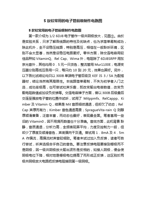
5款较常用的电子管前级制作电路图5款较常用的电子管前级制作电路图第一款介绍为1/2 6DJ8电子管作一级共阴极放大,见图①。
由於是实验关系,只求了解各线路的特性及优缺点,也为求简单易制成功,除此机外,全不设稳压线路,特别是高压,相信在一般聆听环境,区别不会太显著,当然是设稳压电路更好。
零件方面,除交连电容用较佳品种如VitaminQ、Rel Cap、Wima外;电阻除了6DJ8SRPP用东京光音外,其他均用0.5元一只货色;整流管用Mur1100E;电源变压器分别高低压各用一只,每只约10到20元,效果也算好。
另外,以下各比试结论均只以300B单端电子管后级及KEF IS 3/5A为配搭器材,结论当然有其局限性。
本线路简单易制,不失为初学者入门之选,成功率极高,也可尝试校声乐趣,即改变输出电容数值,改变负载电阻数值或加设负反馈等。
交连电容牌子方面,曾以300B后级最后交连至强放电子管的位置作试听,试用了Mitppmfx、RelCappp、Ki mber及Vitamin Q,结果是Mit音质细微通透,但却欠了动态;Rel Cap声厚而有力;Kimber音色通透高贵;SpragueVita-rain Q则醇厚顺滑兼备,泛音丰富,而动态也最好,表现最全面。
笔者喜用一些旧的Vitamin0,因不用煲而数值也十分准确。
音效方面,此机背景聆静,音质通透,分析力高,全频表现算平均,力度及控制力一般,但却少了厚度及顺滑音色,声底偏向干及清。
曾试用1.8mA及4.5m A作偏流,高偏流时声音较细致。
笔者未试过加入负反馈,读者可自行尝试,听声选择合乎自己的音色。
要注意反馈电阻要接到栅极而不是阴极,因一级共阴极放大输出波形是反相的,如接人阴极,便会使阴极电位下降,相对地是栅极电位提高了而形成正反馈,这区别於两极共阴极放大电路把反馈电阻接回第一级阴极。
6DJ8一级共阴极放大,输出电容并了多只 Wima 电容6SN7 SRPP线路第二款是6SN7SRPP线路,相信不少读者试制过此线路,见图②。
手把手教你无线话筒电路
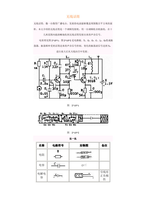
无线话筒无线话筒,像一台微型广播电台,发射的电波能够覆盖周围数百平方米的面积。
本文介绍的无线话筒是一个调频发射机,用一台调频收音机接收,在十几米范围内能清晰地收到无线话筒发射出来的声音信号。
电原理见图2-10-1,图2-10-2是电路板。
T1、C2、C3、C4、L1、C6组成振荡器,振荡频率受到话筒送来的声音信号控制,变化的振荡波信号送到T2,进行放大后从天线向空中发射。
图2-10-1图2-10-2R图2-10-3 图2-10-42.测电解电容C1,方法见图2-10-4。
表棒刚接触电容引线时,指针有较大幅度的摆动,然后回到原来位置。
否则,表示漏电大不能用。
3.测电容C1、C2,方法见图2-10-5。
表棒刚接触电容引线时,指针摆动后回到原来位置,其它电容均为小容量电容,用×1K档测量指针偏转不明显。
4.测晶体管(T),方法见图2-10-6。
万用表量程置NPN档,将二极管的e、b、c插入万用表NPN档的e、b、c中,(hFE)值大于80。
图2-10-5 图2-10-6试一试1.自制线圈L1、L2。
L1用直径0.41毫米漆包线,在直径为3毫米的圆珠笔芯上平绕7圈,其中在第四圈处刮去一些漆,焊上一段电线作为抽头。
L2以同样的方法平绕6圈,脱胎后在线圈的两端引线处刮去油漆以便上锡。
2.将各元件的引线刮净、上锡待用,装配各元件时,引脚要尽量矩,元件贴近电路板。
3.装焊R1、R2、R3、R4、R5。
4.装焊C1,引线有正、负极不要搞错,装C2、C3、C4、C5、C6、C7、C8、C9。
5.装三极管T1、T2。
三极管e、b、c线不能弄错。
装电池夹,注意正负极。
6.装焊L1、L2,最后装焊话简,话筒的引线有极性,不能装错。
见图2—10—7。
7.一段长30厘米左右的软线作为天线焊在电路板的L2处。
仔细核对电路图,确认无误后接上电源。
8.打开调频收音机,把无线话筒靠近收音机,在88—108MH2范围内收听,若收听不到,调整L1的长矩。
Amplitube详细教程

Amplitube详细教程,Amplitube详细教程(连载)!!1、启动SpinAudio ASIO FX 软件2、装载Amplitube3、选择VSTi插件的dll文件4、加载了Amplitube的SpinAudio ASIOamplitube分3个窗口:bypass 直通(相当于没用amplitube)stomp 踏板模板(就是踏板啦!)amp amp模板(失真和eq都在这里哦!)fx 效果模板(混响,eq和延迟功能的加强版)amp模板:tremolo rate 颤音比例(单位时间里颤音的多少)tremolo depth 颤音深度(调节颤音的强弱)pre model 前信号模板sstate clean sstate清音(等于直通)vintage clean 复古清音(声音翠了一些,感觉像低切)tube clean 电子管清音(电子管模拟,有真电子管的朋友就用不着了)British crunch 英国式“咔吃”型失真(软弱的失真,感觉像轻过载,失真度开到头也不是很冲)modren hi-gain 现代高增益失真(很标准的失真,可应用于摇滚,金属等)sstate lead sstate失真(很标准的失真,可应用于摇滚,金属等)fuzz “法兹”失真(比起上面的3个模块,这个法兹模块不是很出色)gain 增益(就是失真度啦)eq model 均衡模板(只有3段,不过值得调节。
)tube America1 1号美国式电子管(很标准的eq)tube Amercia2 2号美国式电子管(去掉了所有中频)British classa 英国式古典(去掉了一些中频)tube British1 1号英国式电子管(使你调整的部分声音大小改变)tube British2 2号英国式电子管(使你调整的部分声音厚度改变,感觉和美国1号相差不大)eq low 低音均衡(这不用多说了吧?)eq mid 中音均衡eq high 高音均衡presence 色彩(调整声音的“闷”度)amp model amp模板tube50w 50瓦电子管(与100瓦比细节削弱)tube100w 100瓦电子管(与50瓦相比更明亮!)sstate100w 100瓦sstate (原声100瓦)sstate30w 30瓦sstate (原声30瓦)amp match amp配合开关(百思不得其解,对不住大家,望高人指点!)volume 音量(这个音量指进入箱体之前的音量,如果你打开了箱体模拟,调节这个音量旋钮会对音色产生轻微影响)reverb 混响(不推荐使用这个混响,可以关闭,然后使用其他软混响)cabinet model 音箱模拟面板small combo 小型音箱(中,低频有削弱,让观众感觉音箱快带不动了似的,有点“收音机”音色的意思)open back 1×12 打开后面1×12 (靠削弱高频来实现音箱背对观众的声效)open back 1×12 II 打开后面1×12二号(没有1号那么夸张)vini open 4×10 毛刺打开4×10 (增加声音细节)mod closed 4×10 中音关闭4×10 (最显著特点为中频没了且低频有所下降)vini closed 4×12 毛刺关闭4×12 (去除细节,使音频块变成大方波!有点金属制造的感觉)mod closed 4×12 中音关闭4×12 (最显著特点为中频没了)british 2×12 英国式2×12 (最显著特点为中低频提升)no speaker 没有箱体模拟(等于直通)cab match cab开关(百思不得其解,对不住大家,望高人指点!)mictype 话筒样式:dynamic 优质话筒(是理想中的话筒,频响曲线巨直,也就是从音箱出来什么样,过话筒还是什么样)condenser 电容话筒(模拟了一个不错的电容话筒在拾音)position 话筒位置:in axis 在音箱中心(不追求特殊效果,就用这个吧)off axis 不在音箱中心(就是声音发“闷”)distance 话筒与箱体距离:near 近(没变化)far 远(感觉就是高音变小了点)gate 噪音门:(这是效果前噪音门,不知道为什么放在这么靠右,功能很弱,不推荐使用,可以考虑在amplitube之前加一个软压限。
- 1、下载文档前请自行甄别文档内容的完整性,平台不提供额外的编辑、内容补充、找答案等附加服务。
- 2、"仅部分预览"的文档,不可在线预览部分如存在完整性等问题,可反馈申请退款(可完整预览的文档不适用该条件!)。
- 3、如文档侵犯您的权益,请联系客服反馈,我们会尽快为您处理(人工客服工作时间:9:00-18:30)。
TUBEMICPRE电子管话放线路
前言:此线路为经典的围绕12AX7这只电子管设计的话放线路,各大厂家的
低端话放产品线路都与之类似,如SAMSON的C-VALVE,ICON的PRE TUBE BEHRINGER MIC200/MIC2200等.可见其经典的程度.
原理分析:
主放大部分:电容话筒输出的平衡信号经过CACON插座输入,先经过反相开关(POLARITY)之后(其实反相开关应该设计在输出部分才更为恰当),进入IC2A
进行平衡放大以及转换为非平衡信号.带#号的电阻要求严格配对,其中6.8K的电阻为话筒的负载电阻,同时给话筒供电.4.7U的电容为偶合电容,作用是
隔离幻象电源.10K电阻为运放偏流电阻,1k与33K的电阻控制这一级的增益,33K/1K=33倍.四个稳压二极管组成限幅电路,限制的电压为稳压管的
标称电压+稳压管的正向导通电压,作用是用来防止信号过大,损坏运放.
懂运放的朋友应该看出来了这一级其实是一个减法器就是用平衡信号中的正相信号
减去反相信号,得到的就是拥有完整振幅的非平衡信号.
电子管部分两只三极管组成两级共阴放大,由于屏压非常低(约24V),工作点也很
低,很容易饱和而产生很大的谐波失真,大家知道电子管效果实际就是一种失真,只是
电子管多产生偶次谐波,所以能美化声音,这里则是故意让它工作在饱和状态产生偶次
失真.TUBEdiver 电位器控制进入电子管的信号大小,也就控制饱和的程度.
Blend电位器和两个470K的电阻组成惠斯通电桥,控制电子管处理过的信号与直接从
IC2A输出的纯净信号的混合比例,即是控制电子管效果的浓度.
IC3A将混合后的信号再次放大,10K电位器控制输出电平.IC3B组成反相放大器
放大倍数为1,用来和IC3B组成平衡输出.之后信号通过CANON插座平衡输出.
电源部分:低端话放为了节约成本,多采用如图的供电线路,为了连接方便电源变压器
次级只有一组绕组,所以要得到双电源,只能用半波整流,为了得到幻相电源高压+48V
只有采用半波倍压整流.发烧友都清楚电源的重要性,正是由于电源部分品质差限制了整个
话放的性能.所以低端的产品虽然也采用了电子管,但往往只是为了做噱头,电子管的成本较高
而整体的售价要低,所以只好牺牲电源部分,正因如此音质往往不能让人满意.所以对于低端的话放
产品,个人推荐采用晶体管的机型,原因很简单,同样的价格,晶体管机型可以有充足的成本来平衡
放大部分和电源部分,因此整体的参数会更优异.而且放大器的染色更少,对于后期的制作空间也更大.。