SG-41 SG-42型数字特斯拉计说明书
DMM 42BUC03-ML 数字多功能测量仪技术参考手册说明书

1.Quick Facts 32.Dimensional Diagrams 5 2.1DMM 42BUC03-ML Board Camera (5)3.I/O Connector 6 3.14-pin I/O Connector (6)3.1.1TRIGGER_IN (6)3.1.2STROBE_OUT (6)4.Spectral Characteristics 74.1Spectral Sensitivity - AR0134 (7)5.Camera Controls 8 5.1Sensor Readout Control (8)5.1.1Pixel Format (8)8-Bit Monochrome (8)5.1.1.15.1.2Frame Rate (8)5.1.3Partial Scan Offset (9)5.2Image Sensor Control (10)5.2.1Exposure Time (10)5.2.2Gain (10)5.3Trigger (10)5.3.1Trigger Mode (10)5.3.2Software Trigger (11)5.4Digital I/O (11)5.4.1General Purpose Input (11)5.4.2General Purpose Output (12)5.5Strobe (12)5.5.1Strobe Enable (12)5.5.2Strobe Polarity (12)6.Revision History 141Quick Facts2Dimensional Diagrams2.1DMM 42BUC03-ML Board Camera3I/O Connector3.14-pin I/O ConnectorRear view of camera1 max. 0.2A (ID) for open drain MOSFET!2 min. 3.5 mA driver strength required!3 G: Ground O: Output I: Input3.1.1TRIGGER_INThe TRIGGER_IN line can be used to synchronize the start of the exposure time with external events. The Trigger section describes in detail how the image sensor's behavior can becontrolled.The current input signal can also be read directly through the General Purpose Input feature.3.1.2STROBE_OUTThe STROBE_OUT line's main usage is to indicate the integration time of the image sensorwhich allows flashes, strobes or other light sources to be synchronized with cameraoperation. The line's behavior can be controlled through the Strobe controls.The output signal can also be directly controlled through the General Purpose Outputfeature.4Spectral Characteristics4.1Spectral Sensitivity - AR01345Camera ControlsThis section describes the parameters available for the DMM 42BUC03-ML camera.The actual name of the parameter depends on the driver technology used to access thecamera. Parameter names are listed for the most common ways to access the cameras:·UVC/V4L2 (on Linux, via uvcvideo)·IC Imaging Control (on Windows, via Device Driver for USB Cameras)5.1Sensor Readout Control5.1.1Pixel FormatThe pixel format defines the data type of the pixels transmitted to the computer. The bitsper pixel needed for a particular pixel format influence the required bandwith.The way the pixel format is controlled varies significantly among the driver technology used to access the camera:·When using the uvcvideo driver on Linux, the pixel format is defined by video4linux2.·When using IC Imaging Control, the pixel format is part of the video format - a parameterwhich combines pixel format, resolution and readout mode. For more information, referto the IC Imaging Control documentation sections on VideoFormat andVideoFormatDesc.The DMM 42BUC03-ML monochrome camera supports multiple pixel formats with variable bits-per-pixel settings. The names of the pixel formats and the way to select them dependson the driver used to control the camera. The following table contains a short overview ofall possible formats followed by a more detailed description.5.1.1.18-Bit MonochromeThis format transmits data using one byte for each pixel.UVC drivers see it with the FourCC Y800.The Device Driver for USB Cameras offers this pixel format as the Y800 video format.5.1.2Frame RateThe frame rate is specified in frames per second and determines the camera's operatingspeed.The way the frame rate is controlled depends greatly upon which driver technology is usedto access the camera:·When using uvcvideo on Linux, the frame rate is selected from a list of available framerates.·When using IC Imaging Control, the frame rate is selected from a list of available framerates through APIs such as Grabber::setFPS orICImagingControl.DeviceFrameRate.The range of available frame rates depends upon other camera settings such as well, pixelformat, resolution and readout modes.The following tables show the maximum frame rate for some combinations of pixel format and resolution.8-Bit Monochrome5.1.3Partial Scan OffsetIf the selected resolution is smaller than the sensor size, the part of the sensor that isactually read out can be specified by the Partial Scan Offset X and Partial Scan Offset Yparameters. By default, the camera automatically positions the offsets so that the center of the sensor is used.5.2Image Sensor Control5.2.1Exposure TimeThe Exposure Time parameter defines the time the camera opens its (electronic) shutterwhen it is taking an image.5.2.2GainThe Gain parameter defines the amplification that is applied to the image at sensor level.5.3TriggerThe trigger mode can be used to take images at very specific points in time which arespecified by an electrical signal connected to the TRIGGER_IN pin of the I/O connector of the camera.5.3.1Trigger ModeThe Trigger Mode parameter enables the trigger mode.5.3.2Software TriggerThe Software Trigger function can be used to simulate a trigger pulse, in turn causing oneimage to be exposed and delivered to the host computer.5.4Digital I/OThe One4All series has one digital input and one digital output. The digital input can beused as a Trigger input but the current status can also examined directly.The digital output can be configured as a Strobe output to signal the exact moment when the image sensor is sensitive to light so that external light sources can be synchronized to its operation cycle.5.4.1General Purpose InputThe General Purpose Input parameter allows the current status of the TRIGGER_IN pin.5.4.2General Purpose OutputThe General Purpose Output parameter controls the status of the STROBE_OUT pin.5.5StrobeThe strobe function controls the automatic generation of output pulses on theSTROBE_OUT pin which is synchronized to the image sensor's exposure time.5.5.1Strobe EnableThe Strobe Enable parameter enables the automatic generation of strobe pulses.5.5.2Strobe PolarityThe Strobe Polarity parameter can be used to invert the strobe pulse output.6Revision HistoryDMM 42BUC03-ML Technical Reference ManualAll product and company names in this document may be trademarks and tradenames of their respective owners and are hereby acknowledged.The Imaging Source Europe GmbH cannot and does not take any responsibility or liability for any information contained in this document. The source code presented in this document is exclusively used for didactic purposes. The Imaging Source does not assume any kind of warranty expressed or implied, resulting from the use of the content of this document or the source code.The Imaging Source Company reserves the right to make changes in specifications, function or design at any time and without prior notice.Last update: May 2023© 2023 The Imaging SourceAll rights reserved. Reprint, also in parts, only allowed with permission of The Imaging Source Europe GmbH.All weights and dimensions are approximate. Unless otherwise specified, the lenses shown in the context of cameras are not shipped with these cameras.Headquarters:The Imaging Source Europe GmbHÜberseetor 18, D-28217 Bremen, GermanyPhone: +49 421 33591-0North & South America:The Imaging Source, LLCSuite 470, 4600 Park Road, Charlotte, NC 28209, United StatesPhone: +1 877-462-4772Asia Pacific:The Imaging Source Asia Co., Ltd.3F., No. 43-7/8, Zhongxing RoadNew Taipei City, Xizhi District 221012, Chinese TaipeiPhone: +886 2-2792-3153。
磁悬浮原理

磁悬浮原理实验目的1.观察自稳定的磁悬浮物理现象;2.深化学生对磁悬浮的原理的认识;3.培养动手观察思考能力,锻炼较强的耐心。
实验原理1. 磁学基本知识磁性:物质能吸引铁、钴、镍等金属的特性。
磁体:具有磁性的物体。
磁极:磁体上磁性最强的部分就是磁极。
当把两块磁铁放在一起相互靠近时,有时候互相吸引,有时候相互排斥。
现在人们都知道磁体有两个极,一个称N极,一个称S极。
同性极相互排斥,异性极相互吸引。
磁极是由环形电流元产生。
磁力是由于电荷运动所产生的基本力。
地球也是一个大磁体,它的两个极分别在接近地理南极和地理北极的地方。
因此地球表面的磁体,可以自由转动时,就会因磁体同性相斥,异性相吸的性质指示南北。
地球磁场的磁极和地理上的南北级方向正相反,而且和地球南北极并不重合,两者之间有一个11度左右的夹角,叫磁偏角。
此外地球磁场的磁极位置不是固定的,它有一个周期性变化。
地磁场强度很弱,在最强的两极其强度不到10-4(T), 平均强度约为0.6×10⁻⁴(T)。
2. 磁悬浮磁悬浮就是运用磁体“同性相斥,异性相吸”的性质,使磁体具有抗拒地心引力的能力悬浮起来,即“磁性悬浮”。
目前世界上有三种类型的磁悬浮。
一是以德国为代表的常导电式磁悬浮,二是以日本为代表的超导电动磁悬浮,这两种磁悬浮都需要用电力来产生磁悬浮动力。
而第三种,就是我国的永磁悬浮,它利用特殊的永磁材料,不需要任何其他动力支持。
(1)电磁悬浮系统(electromagnetic levitation ):简称EML技术。
它的主要原理是利用高频电磁场在金属表面产生的涡流来实现对金属球的悬浮。
将一个金属样品放置在通有高频电流的线圈上时,高频电磁场会在金属材料表面产生一高频涡流,这一高频涡流与外磁场相互作用,使金属样品受到一个洛沦兹力的作用。
在合适的空间配制下,可使洛沦兹力的方向与重力方向相反,通过改变高频源的功率使电磁力与重力相等,即可实现电磁悬浮。
fluke中文使用手册421

数字计量器的使用说明书

Digi DC-782 operation ManualDC-782Counting ScaleVersion 1.006Operation ManualT o be the best by every measure109429ContentsAbout This Manual (1)1.0 Introduction (1)1.1 Capacities and Resolutions . . . . . . . . . . . . . . . . . . . . . . . . . . . . . . . . . . . . . . . . . . . . . . . . . . . . . . . . 11.2 Modes of Operation . . . . . . . . . . . . . . . . . . . . . . . . . . . . . . . . . . . . . . . . . . . . . . . . . . . . . . . . . . . . . . 11.3 Keyboard and Display . . . . . . . . . . . . . . . . . . . . . . . . . . . . . . . . . . . . . . . . . . . . . . . . . . . . . . . . . . . . 21.3.1 Display Specifications . . . . . . . . . . . . . . . . . . . . . . . . . . . . . . . . . . . . . . . . . . . . . . . . . . . . . . . . . . . . . . 21.3.2 Indicator Lamps . . . . . . . . . . . . . . . . . . . . . . . . . . . . . . . . . . . . . . . . . . . . . . . . . . . . . . . . . . . . . . . . . . 21.3.3 Key Functions. . . . . . . . . . . . . . . . . . . . . . . . . . . . . . . . . . . . . . . . . . . . . . . . . . . . . . . . . . . . . . . . . . . . 32.0 Installation (5)2.1 Unpacking . . . . . . . . . . . . . . . . . . . . . . . . . . . . . . . . . . . . . . . . . . . . . . . . . . . . . . . . . . . . . . . . . . . . . 52.2 Repacking . . . . . . . . . . . . . . . . . . . . . . . . . . . . . . . . . . . . . . . . . . . . . . . . . . . . . . . . . . . . . . . . . . . . . 52.3 Setting Up . . . . . . . . . . . . . . . . . . . . . . . . . . . . . . . . . . . . . . . . . . . . . . . . . . . . . . . . . . . . . . . . . . . . . 52.4 Powering Up the DC-782. . . . . . . . . . . . . . . . . . . . . . . . . . . . . . . . . . . . . . . . . . . . . . . . . . . . . . . . . . 62.4.1 AC Power Source. . . . . . . . . . . . . . . . . . . . . . . . . . . . . . . . . . . . . . . . . . . . . . . . . . . . . . . . . . . . . . . . . 62.4.2 DC Battery Pack Replacement/Installation. . . . . . . . . . . . . . . . . . . . . . . . . . . . . . . . . . . . . . . . . . . . . . . 72.4.3 Battery Charging. . . . . . . . . . . . . . . . . . . . . . . . . . . . . . . . . . . . . . . . . . . . . . . . . . . . . . . . . . . . . . . . . . 82.4.4 Start-Up Screens . . . . . . . . . . . . . . . . . . . . . . . . . . . . . . . . . . . . . . . . . . . . . . . . . . . . . . . . . . . . . . . . . 82.5 Replacement Parts. . . . . . . . . . . . . . . . . . . . . . . . . . . . . . . . . . . . . . . . . . . . . . . . . . . . . . . . . . . . . . . 92.6 Block Diagram of Electrical Connections . . . . . . . . . . . . . . . . . . . . . . . . . . . . . . . . . . . . . . . . . . . . . 102.7 Physical Layout of Electrical Connections. . . . . . . . . . . . . . . . . . . . . . . . . . . . . . . . . . . . . . . . . . . . . 113.0 Configuration Settings (12)3.1 Putting the Scale in Maintenance Mode . . . . . . . . . . . . . . . . . . . . . . . . . . . . . . . . . . . . . . . . . . . . . . 123.2 Configuring Specification 141 and 142 Settings from the Scale Keyboard . . . . . . . . . . . . . . . . . . . . 123.2.1 Customer Specification (141 Settings). . . . . . . . . . . . . . . . . . . . . . . . . . . . . . . . . . . . . . . . . . . . . . . . . 123.2.2 Weight and Measurement Specifications (142 Settings). . . . . . . . . . . . . . . . . . . . . . . . . . . . . . . . . . . . 144.0 Calibration (17)5.0 Scale Operations (19)5.1 Counting Scale Accuracy. . . . . . . . . . . . . . . . . . . . . . . . . . . . . . . . . . . . . . . . . . . . . . . . . . . . . . . . . 195.2 Setting Tare Weights in Weighing Mode. . . . . . . . . . . . . . . . . . . . . . . . . . . . . . . . . . . . . . . . . . . . . . 195.2.1 One Touch Tare (When the Tare Weight is Unknown) . . . . . . . . . . . . . . . . . . . . . . . . . . . . . . . . . . . . . 205.2.2 Digital Tare (When Tare Weight is Known in Advance). . . . . . . . . . . . . . . . . . . . . . . . . . . . . . . . . . . . . 205.2.3 Tare Addition or Subtraction . . . . . . . . . . . . . . . . . . . . . . . . . . . . . . . . . . . . . . . . . . . . . . . . . . . . . . . . 205.3 Entering Unit Weights. . . . . . . . . . . . . . . . . . . . . . . . . . . . . . . . . . . . . . . . . . . . . . . . . . . . . . . . . . . . 205.3.1 Unit Weight Operation by Sampling. . . . . . . . . . . . . . . . . . . . . . . . . . . . . . . . . . . . . . . . . . . . . . . . . . . 215.3.2 Unit Weight Operation by Key Entry. . . . . . . . . . . . . . . . . . . . . . . . . . . . . . . . . . . . . . . . . . . . . . . . . . . 215.4 Operations Without Recalling an Item Code . . . . . . . . . . . . . . . . . . . . . . . . . . . . . . . . . . . . . . . . . . . 225.4.1 A Single Counting Operation - Without Recalling an Item Code. . . . . . . . . . . . . . . . . . . . . . . . . . . . . . 225.4.2 Part Accumulation or Subtraction and Negative Counting - Without Recalling an Item Code. . . . . . . . 225.5 Using Item Codes in Weighing Mode . . . . . . . . . . . . . . . . . . . . . . . . . . . . . . . . . . . . . . . . . . . . . . . . 245.5.1 Recalling Item Codes using Item Code Number . . . . . . . . . . . . . . . . . . . . . . . . . . . . . . . . . . . . . . . . . 245.5.2 Delete Item Memory . . . . . . . . . . . . . . . . . . . . . . . . . . . . . . . . . . . . . . . . . . . . . . . . . . . . . . . . . . . . . . 246.0 Scale Programming (25)6.1 Checking Memory Status. . . . . . . . . . . . . . . . . . . . . . . . . . . . . . . . . . . . . . . . . . . . . . . . . . . . . . . . . 256.2 Program Item Code, Tare Weight, Unit Weight, Setpoint 1 and 2. . . . . . . . . . . . . . . . . . . . . . . . . . .25i6.3 Program a General Setpoint . . . . . . . . . . . . . . . . . . . . . . . . . . . . . . . . . . . . . . . . . . . . . . . . . . . . . . 276.4 Programming a Preset Key . . . . . . . . . . . . . . . . . . . . . . . . . . . . . . . . . . . . . . . . . . . . . . . . . . . . . . . 276.5 Delete Item Memory . . . . . . . . . . . . . . . . . . . . . . . . . . . . . . . . . . . . . . . . . . . . . . . . . . . . . . . . . . . . 287.0 RS-232C Communication with PC (29)7.1 Connection . . . . . . . . . . . . . . . . . . . . . . . . . . . . . . . . . . . . . . . . . . . . . . . . . . . . . . . . . . . . . . . . . . . 297.2 General Specifications of the RS-232C Interface . . . . . . . . . . . . . . . . . . . . . . . . . . . . . . . . . . . . . . . 297.3 Setting the Scale Specifications for Communication to a PC . . . . . . . . . . . . . . . . . . . . . . . . . . . . . . 297.4 Communication Method . . . . . . . . . . . . . . . . . . . . . . . . . . . . . . . . . . . . . . . . . . . . . . . . . . . . . . . . . 307.4.1 Standard Stream Data Transmission (Continuous) . . . . . . . . . . . . . . . . . . . . . . . . . . . . . . . . . . . . . . . 307.4.2 Standard Manual Data Transmission. . . . . . . . . . . . . . . . . . . . . . . . . . . . . . . . . . . . . . . . . . . . . . . . . . 317.4.3 Standard Command Data Transmission . . . . . . . . . . . . . . . . . . . . . . . . . . . . . . . . . . . . . . . . . . . . . . . 327.5 Characters That Can Be Transmitted by RS-232C. . . . . . . . . . . . . . . . . . . . . . . . . . . . . . . . . . . . . . 327.6 RS-232C Data Transmission Formats . . . . . . . . . . . . . . . . . . . . . . . . . . . . . . . . . . . . . . . . . . . . . . . 33 1.0 Appendix (37)1.1 DC-782 Specifications. . . . . . . . . . . . . . . . . . . . . . . . . . . . . . . . . . . . . . . . . . . . . . . . . . . . . . . . . . . 371.2 DC-782 Error Message List. . . . . . . . . . . . . . . . . . . . . . . . . . . . . . . . . . . . . . . . . . . . . . . . . . . . . . . 382.0 DC-782 Limited Warranty (39)ii DC-782 Operation ManualThis is a “Table of Contents preview” for quality assuranceThe full manual can be found at /estore/catalog/ We also offer free downloads, a free keyboard layout designer, cable diagrams, free help andsupport. : the biggest supplier of cash register and scale manuals on the net。
优利德 UTE9800系列使用手册智能电参数测量仪 说明书

UTE9802/9811 智能电参数测量仪使用说明书UTE9802UTE9811前言感谢您购置优利德智能电参数测量仪,为了确保正确使用本仪器,在操作仪器之前请仔细阅读手册,特别是有关“安全事项”部分。
如已阅读完手册,建议您将此手册妥善保管,以便在将来使用过程中进行查阅。
版权信息UNI-T 优利德科技(中国)股份有限公司版权所有。
UNI-T 产品受中国或其他国家专利权的保护,包括已取得或正在申请的专利。
本公司保留更改产品规格和价格的权利。
UNI-T 保留所有权利。
许可软件产品由UNI-T及其子公司或提供商所有,受国家版权法及国际条约规定的保护。
本文中的信息将取代所有以前出版的资料中的信息。
UNI-T 是优利德科技(中国)股份有限公司(Uni-Trend Technology(China) Limited)的注册商标。
保固服务仪器自购买之日起保修期壹年,在保修期内由于使用者操作不当而损坏仪器的,维修费及由于维修所引起的费用由用户承担,仪器由本公司负责终身维修。
如果原购买者自购该产品之日一年内,将该产品出售或转让给第三方,则保修期应为自原购买者从UNI-T 或授权的UNI-T分销商购买该产品之日起一年内。
电源线及其他附件和保险丝等不受此保证的保护。
如果在适用的保修期内证明产品有缺陷,UNI-T可自行决定是修复有缺陷的产品且不收部件和人工费用,或用同等产品(由UNI-T决定)更换有缺陷的产品。
UNI-T作保修用途的部件、模块和更换产品可能是全新的,或者经修理具有相当于新产品的性能。
所有更换的部件、模块和产品将成为UNI-T的财产。
以下提到的“客户”是指据声明本保证所规定权利的个人或实体。
为获得本保证承诺的服务,“客户”必须在适用的保修期内向UNI-T通报缺陷,并为服务的履行做适当安排。
客户应负责将有缺陷的产品装箱并运送到UNI-T指定的维修中心,同时预付运费并提供原购买者的购买证明副本。
如果产品要运到UNI-T维修中心所在国范围的地点,UNI-T应支付向客户送返产品的费用。
高斯计特斯拉计使用详细说明书

仪器名称 HM-100 高斯计
出厂检定记录 仪器编号
出厂日期 年月日
检验项目及技术标准要求
检验标准
检验结论
1、文字符号清晰
合格
检验人员
外观 检查
2、无伤痕变形 3、开关动作正常
合格 合格
4、包装完好
零位 漂移 基本 误差
30 分钟不超过±1 字 ±1%满度±1 字
送修 日期
故障描述
合格 合格 合格 返修记录 实际情况
机、退磁机、微波炉、焊接机、电机等周围请不要使用。 建议您定期进行校准工作。 四.维修及注意点 1. 当仪器在测量状态时,如调零不起作用或测量磁体无读数,则应首先检 查供电电源是否正常,其次检查传感器是否损坏,如传感器表面无损坏、 接线完好,则可能仪器内部出现故障,建议客户将仪器寄回本公司进行 检修。 2. 传感器切不可受力、撞击或受挤压,以免损坏。 3. 调零时传感器应放置在远离磁场的地方,否则会造成测量误差。 4. 仪器保修期为 12 个月。注:传感器为易损件不在保修范围。 5. 仪器应避免在不符合使用环境条件下使用。 6. 如在测量时发现测量数值确实有偏差,则可用工具旋转传感器手柄上的 电位器进行微调以达到正确的测量结果。
(纵向传感器)紧密接触被测材料表面(直流磁场)或被测的磁场位置进行 测量,液晶显示即为被测磁场的大小。 8、 重置峰值保持
在峰值保持测量状态的测量过程中,如需重新测定峰值,而此峰值预计 比原峰值小,则可按 Zear 键使之重新读入峰值。
因为当仪器进入峰值保持状态后必须有比现有显示值大的值时数据显 示才改变,如果所测数据比现有显示值小,刚显示值不改变。所以此时必须 按峰值重置。
概述一霍尔效应原理hm100便携式数字高斯计可用于测量直流磁场辐射磁场剩磁地球磁将金属或半导体薄片置于磁场中当有电流流过时在垂直于电流和磁场等等各类磁场的磁感应强度
Omega L-75HH40 Series 温度计手持计说明书

HH42
499 Handheld thermistor thermometer with RS232 communications
100 (212)
±0.066 (0.119)
110 (230)
±0.088 (0.158)
120 (248)
±0.117 (0.211)
130 (266)
±0.156 (0.281)
30 (86)
±0.015 (0.027)
(2252 Ω) probes with 1⁄4" phone jack (Model PPM-2) connection
40 (104)
±0.017 (0.031)
AVAILABLE FOR FAST DELIVERY!
50 (122) 60 (140) 70 (158) 80 (176) 90 (194)
Case Material: ABS
-10 (14)
±0.015 (0.027)
selection for auto or manual shut-off
Dimensions:
0 (32)
±0.015 (0.027)
mode; auto shut-off in 10-min with no function key entry
Ordering Example: HH41, thermometer, and HH40-AC, 110 Vac adaptor, $425 + 56 = $481.
L-76
)UHHSKRQH _ ,QWHUQDWLRQDO _ )D[ _ 6DOHV#RPHJDFRXN
ZZZRPHJDFRXN
81,7(' 67$7(6 ZZZRPHJDFRP 7&20(*$
胜利仪器 VICTOR 862A 862B 862C数显特斯拉计说明书
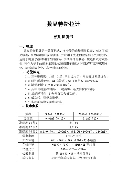
数显特斯拉计使用说明书一、概述数显特斯拉计是一款便携式、多功能的磁场测量仪器,配备了高灵敏度、低飘移的霍尔传感器,并应用了先进的数字信号处理技术,适用于测量永磁材料的表面磁场、机械零件的剩磁、磁选机或除铁器等。
可作为基本的磁参量测量仪器应用于磁性材料生产厂家和应用单位、机械制造企业、高校科研单位等。
二、功能特点2.1三种准确度:1级、2级、5级适用于不同的磁场测量场合。
2.2两种磁场单位:mT(毫特)、Gs(高斯),1mT=10Gs。
2.3测量范围:0-2400mT(24000Gs)。
2.4具有自动量程切换、一键清零、最大值保持功能。
2.5显示屏背光、5分钟自动关机功能。
2.6低功耗、轻便易携带。
2.7多种霍尔探头可供选择。
三、技术参数量程200mT(2000Gs)2000mT(20000Gs)分度值0.01mT(0.1G)0.1mT(1G)准确度(1级)±1.0%准确度(2级)±2.0%准确度(5级)±2.0%(0...1000mT),±5.0%(1000mT...2400mT)供电电源1节9V电池工作环境0℃~50℃,20%~85%R·H,不结露存储环境-20℃~70℃,<85%R·H,不结露仪器尺寸160mm×75mm×34mm仪器重量约260克(含电池及导线)霍尔探头标配径向霍尔探头,导线约长1米四、外观结构4.1外观4.2显示屏1、量程提示:当测量的磁场不足200mT时,默认量程为200mT;当超过200mT时,量程自动切换为2000mT。
2、磁场极性:当磁场方向是从霍尔传感器正面穿过时,屏幕显示为“N”;当磁场方向是从霍尔传感器背面穿过时,屏幕显示为“S”。
3、测量数值:霍尔传感器以数显的形式显示测量的磁场数值。
4、峰值模式:当屏幕显示“Peak”即为峰值模式,磁场数值显示一段时间内测量到的最大值并保持不变。
- 1、下载文档前请自行甄别文档内容的完整性,平台不提供额外的编辑、内容补充、找答案等附加服务。
- 2、"仅部分预览"的文档,不可在线预览部分如存在完整性等问题,可反馈申请退款(可完整预览的文档不适用该条件!)。
- 3、如文档侵犯您的权益,请联系客服反馈,我们会尽快为您处理(人工客服工作时间:9:00-18:30)。
SG-41/ SG-42型数字特斯拉计说明书
本仪器是根据霍尔效应原理设计的台式数字式高斯计/特斯拉计。
它具有量程宽(10T)、分辨力(10μT)、性能稳定、读数清晰准确等特点。
该仪器由4 1/2位LED发光字符显示,电子线路部分具有0.05%的线性度, 仪表的准确度主要取决于霍尔元件的磁线性度与稳定性。
SG-41型高斯计/特斯拉计具有0.5%的准确度,而SG-42型高斯计/特斯拉计的准确度为1%。
本仪器具有模拟输出口,可外接示波器、函数记录仪或其他测量仪表,用以观察磁场的变化波形,间接测量交流磁场的平均值、有效值或峰值。
本仪器具有显示清晰、操作简便、性能可靠的特点。
可广泛用于空间磁场、磁性材料、磁性元件和装置的测量,也可作为磁感应强度的标准使用(应具有计量部门的检定证书)。
主要技术指标
1.测量范围:分200mT、2T和10T三个量程
2.显示位数: 4 1/2 位LED发光数码管
3.采样速率: 2.5次/秒
4.最高分辨力:10μT
5.准确度:(在20℃±2℃的条件下、在20mT~1.6T的磁感应强度范内)SG-41型:准确度为0.5%(读数)±0.01%(满度)
SG-42型:准确度为1% (读数)±0.01% (满度)
6. 噪声:≤2个字
7. 极性辨别:当显示为“+”值时,探头注明“ N”面,面对磁场“ N”极
8. 模拟输出:1mV/mT
9. 过载能力:外磁场过载不会引起仪器损坏,过载时,所有数字闪跳。
10.尺寸:(W×H×D)260×105×287
11.重量:约 2 kg
标配是1.4毫米厚,4毫米宽的测头。