扩展课4 链路聚合(端口聚合)
端口聚合——精选推荐

端⼝聚合实训六端⼝聚合实验名称:端⼝聚合。
实验⽬的:掌握链路聚合的配置及原理,理解端⼝聚合的作⽤和特点。
技术原理:端⼝聚合(Aggregate-port)⼜称链路聚合,是指两台交换机之间在物理上将多个端⼝连接起来,将多条链路聚合成⼀条逻辑链路,形成⼀个拥有较⼤宽带的端⼝,从⽽形成⼀条⼲路,增⼤链路带宽,可以实现均衡负载,并提供冗余链路。
实现功能:实现链路备份聚合,增加交换机之间的传输带宽,可在冗余链路上实现均衡负载。
实验设备:cisco2960⼀台,cisco2950⼀台,PC四台,直连线2根,交叉线2根,配置线2根。
实验拓朴:1.端⼝聚合提供冗余备份链路背景描述:某企业采⽤两台交换机组成⼀个局域⽹,由于很多数据流量是跨交换机进⾏转发的,因此需要提⾼交换机之间的传输带宽,并实现链路冗余备份,为此⽹络管理员在两台交换机之间采⽤两根⽹线互连,并将相应的两个端⼝聚合为⼀个逻辑端⼝,现在要在交换机上做适当配置来实现这⼀⽬标。
技术原理:端⼝聚合(Aggregate-port)⼜称链路聚合,是指两台交换机之间在物理上将多个端⼝连接起来,将多条链路合成⼀条逻辑链路。
从⽽增⼤链路带宽,解决交换⽹络中因带宽引起的⽹络瓶颈问题。
多条物理链路之间能够相互冗余备份,其中任意⼀条链路断开,不会影响其他链路的正常转发数据。
实验注意事项:按照拓扑图连接⽹络时,两台交换机都配置完端⼝聚合后,再将两台交换机连接起来,如果先连线再配置会造成⼴播风暴,影响交换机的正常⼯作。
实验步骤:步骤1:switch0的基本配置Switch0>Switch0>enableSwitch0#configure terminalSwitch0(config)#vlan 10Switch0(config-vlan)#name test10Switch0(config-vlan)#exitSwitch0(config)#interface fastethernet 0/5Switch0(config-if)#switchport access vlan 10Switch0(config-if)#endSwitch0#show vlanVLAN Name Status Ports---- -------------------------------- --------- -------------------------------1 default active Fa0/1, Fa0/2, Fa0/3, Fa0/4 Fa0/6, Fa0/7, Fa0/8, Fa0/9Fa0/10, Fa0/11, Fa0/12, Fa0/13Fa0/14, Fa0/15, Fa0/16, Fa0/17Fa0/18, Fa0/19, Fa0/20, Fa0/21Fa0/22, Fa0/23, Fa0/2410 test10 active Fa0/5步骤2:switch0上配置聚合端⼝Switch0(config)#interface port-channel 1Switch0(config-if)#switchport mode trunkSwitch0(config-if)#exitSwitch0(config)#interface range fastethernet 0/1-2Switch0(config-if-range)#channel-group 1 mode onupSwitch0(config-if-range)#endSwitch0#show run //查看端⼝聚合信息Building configuration...Current configuration : 990 bytes!version 12.1no service password-encryption!hostname Switch0!!!interface FastEthernet0/1channel-group 1 mode on!interface FastEthernet0/2channel-group 1 mode on!interface FastEthernet0/3!interface FastEthernet0/4!interface FastEthernet0/5switchport access vlan 10步骤3.在Switch1的基本配置Switch1>Switch1>enableSwitch1#config terSwitch1(config)#vlan 10Switch1(config-vlan)#name sales Switch1(config-vlan)#exitSwitch1(config)#interface fastethernet 0/5Switch1(config-if)#switchport access vlan 10Switch1(config-if)#endSwitch#show vlan id 10步骤4.在switch1上配置聚合端⼝Switch1#config terSwitch1(config)#interface port-channel 1Switch1(config-if)#switchport trunkSwitch1(config-if)#switchport mode trunkSwitch1(config-if)#exitSwitch1(config)#interface range fastethernet 0/1-2Switch1(config-if-range)#channel-group 1 mode onupSwitch1(config-if-range)#endSwitch1#show etherchannel步骤5.验证当交换机之间的⼀条链路断开时,PC1和PC2仍能互相通信. C:\>ping 192.168.10.20 Pinging 192.168.10.20 with 32 bytes of data:Reply from 192.168.10.20: bytes=32 time=94ms TTL=128Reply from 192.168.10.20: bytes=32 time=93ms TTL=128Reply from 192.168.10.20: bytes=32 time=94ms TTL=128Reply from 192.168.10.20: bytes=32 time=94ms TTL=1282.核⼼交换机(三层交换)和⼆层交换之间的端⼝聚合2950Switch>enSwitch#conf tEnter configuration commands, one per line. End with CNTL/Z.Switch(config)#int f0/1Switch(config-if)#channel-group 1 mode on%LINK-5-CHANGED: Interface Port-channel 1, changed state to up %LINEPROTO-5-UPDOWN: Line protocol on Interface Port-channel 1, changed state to upSwitch(config-if)#int f0/2Switch(config-if)#channel-group 1 mode on3560Switch(config)#int port-channel 1Switch(config-if)#exitSwitch(config)#ip routing(默认已经启⽤了路由功能)Switch(config)#int port-channel 1Switch(config-if)#no switchportSwitch(config-if)#ip add 1.1.1.1 255.0.0.0Switch(config-if)#no shutSwitch(config-if)#exitSwitch(config)#int f0/1Switch(config-if)#no switchport%LINEPROTO-5-UPDOWN: Line protocol on Interface FastEthernet0/1, changed state to down%LINEPROTO-5-UPDOWN: Line protocol on Interface FastEthernet0/1, changed state to upSwitch(config-if)#Switch(config-if)#no ip addSwitch(config-if)#channel-group 1 mode ?active Enable LACP unconditionallyauto Enable PAgP only if a PAgP device is detecteddesirable Enable PAgP unconditionallyon Enable Etherchannel onlypassive Enable LACP only if a LACP device is detectedSwitch(config-if)#channel-group 1 mode on%LINK-5-CHANGED: Interface Port-channel 1, changed state to up%LINEPROTO-5-UPDOWN: Line protocol on Interface Port-channel 1, changed state to upSwitch(config-if)#Switch(config-if)#int f0/2Switch(config-if)#no switchport%LINEPROTO-5-UPDOWN: Line protocol on Interface FastEthernet0/2, changed state to down%LINEPROTO-5-UPDOWN: Line protocol on Interface FastEthernet0/2, changed state to upSwitch(config-if)#no ip add Switch(config-if)#no ip addressSwitch(config-if)#channel-group 1 mode onSwitch(config-if)#exitSwitch(config)#int f0/3Switch(config-if)#no switchport%LINEPROTO-5-UPDOWN: Line protocol on Interface FastEthernet0/3, changed state to down%LINEPROTO-5-UPDOWN: Line protocol on Interface FastEthernet0/3, changed state to upSwitch(config-if)#ip add 2.2.2.1 255.0.0.0Switch(config-if)#no shut端⼝聚合可使流量在多条物理链路上负载均衡,同时也起到了链路的备份作⽤。
端口聚合_精品文档

端口聚合摘要:端口聚合是一种网络技术,它允许多个物理端口被虚拟化为一个逻辑端口,以提高网络带宽和可靠性。
本文将介绍端口聚合的原理和工作方式,并讨论其在网络环境中的应用和优势。
一、引言随着网络流量的迅速增长,企业和组织对网络带宽和可靠性的需求也越来越高。
传统的网络设计通常使用单个物理端口连接交换机和服务器,但这种设计容易成为瓶颈,限制了网络的性能和可扩展性。
为了解决这个问题,端口聚合技术应运而生。
二、端口聚合的原理端口聚合利用网络链路上的多个物理端口,将它们虚拟化为一个逻辑端口。
这样,网络设备可以同时利用多个物理链路的带宽,从而提高网络的吞吐量和可用性。
端口聚合的实现方式通常有两种:静态和动态。
1. 静态端口聚合静态端口聚合需要手动配置网络设备。
管理员需要指定哪些物理端口将被聚合,并设置逻辑端口的参数,如带宽和可用性要求。
一旦配置完成,网络设备将根据指定的规则来动态分配网络流量。
静态端口聚合的优点在于简单、稳定。
管理员可以根据实际需求进行灵活的配置,以实现最佳性能。
2. 动态端口聚合动态端口聚合利用一种协议,如LACP(链路聚合控制协议),自动配置网络设备。
LACP允许网络设备进行交互,以协商和管理端口聚合。
它提供了更高的灵活性和可靠性。
动态端口聚合的优点在于网络自动适应变化。
当有新的物理链路加入或者失败时,网络设备可以自动重分配流量,以实现负载均衡和故障恢复。
三、端口聚合的应用端口聚合技术在许多网络环境中都有广泛的应用。
以下是一些常见的应用场景:1. 数据中心网络在大型数据中心环境中,服务器和网络交换机之间的连接通常需要高带宽和可靠性。
端口聚合可以满足这些要求,同时也简化了网络拓扑的管理。
管理员可以根据实际需求动态分配流量,以优化网络性能。
2. 高速网络在需要高速数据传输的网络中,端口聚合可以提供更大的带宽和容错能力。
例如,在视频监控系统中,多个网络摄像头可以通过端口聚合技术连接到视频录像服务器,以提供更高的视频帧率和清晰度。
4-端口聚合实验资料
0分计。
4. 实验报告文件以PDF 格式提交。
【实验目的】理解链路聚合的配置及原理。
【实验内容】(1) 完成实验教程第三章实例3-5的实验,回答实验提出的问题及实验思考。
(P99-102) (2) 端口聚合和生成树都可以实现冗余链路,这两种方式有什么不同?(3) 你认为本实验能实现负载平衡吗?如果不能,请讨论原因并设计方法,进行实验验证。
【实验要求】一些重要信息信息需给出截图,注意实验步骤的前后对比。
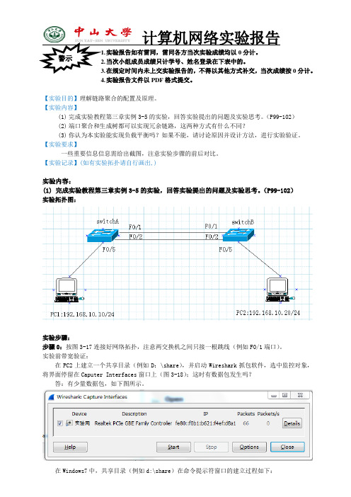
【实验记录】(如有实验拓扑请自行画出,)实验内容:(1) 完成实验教程第三章实例3-5的实验,回答实验提出的问题及实验思考。
(P99-102) 实验拓扑图:实验步骤:步骤0:按图3-17连接好网络拓扑,注意两交换机之间只接一根跳线(例如F0/1端口)。
实验前带宽验证:在PC2上建立一个共享目录(例如D :\share ),并启动Wireshark 抓包软件,选中监控对象,将界面停留在Caputer Interfaces 窗口上(图3-18);这时有数据包发生吗?答:有少量数据包,如下图所示。
在Windows7中,共享目录(例如d:\share )在命令提示符窗口的建立过程如下:md d:\share \\ 在D盘建立文件夹sharenet user B403 159357 \\ 建立用户B403、口令是159357net share myshare=d:\share /grant:B403,full\\ 建立d:\share的共享名为myshare,访问用户myuser、权限full在PC1上选择一文件包,在“开始”|“搜索程序和文件”的对话框中输入\\192.168.10.20\myshare,输入用户名/口令,就进入了共享文件夹。
将PC1上的一个文件包复制到PC2的共享目录,我选择UPK1(5).rar,大小为1.5GB。
选择“开始”|“运行”菜单命令,在弹出的“运行”对话框中输入\\192.168.10.20\share;将文件包复制到PC2的共享目录,注意观察包数量的变化,记录Packets、Packets/s的代表值。
端口聚合

SW1#show aggregatePort load-balance Load-balance : Destination MAC
六、项目实施
(一)项目实施流程
项目开始 了解项目情境 解决方案
项目实施流程图
理解项目需求分析 学习并掌握新技术
理论复习
分析问题
项目实施设备选型
网络设备连接
项目验收 项目总结
配置流量平衡
Switch (config)#aggregateport load-balance {dst-mac|src-mac|src-dstmac|dst-ip|src-ip|ip } 注意:以RG-S3750-24型号的交换机为例,不同型号交换机支持的流量平 衡算法可能会不同
配置端口聚合
标准为IEEE 802.3ad 可扩展链路带宽 实现成员端口上的流量平衡 自动链路冗余备份
1000M
Aggregate Link
1000M 1000M
10/100M
10/100M
端口聚合的流量平衡
流量平衡:把流量平均地分配 到AP的成员链路中去
可以根据源MAC地址、目的 MAC地址或源IP地址/目的IP地 址 应根据不同的网络环境设置合适 的流量分配方式
SW2 F0/1 F0/2
端口聚合配置实例
在SW1上查看配置结果:
SW1#show aggregatePort 1 summary AggregatePort MaxPorts SwitchPort Mode Ports ------------- -------- ---------- ------ ---------------------------------Ag1 8 Enabled ACCESS Fa0/1 ,Fa0/2
链路聚合的操作解释

链路聚合的操作解释
链路聚合是一种网络技术,用于将多个物理链路(例如以太网、光纤等)组合成一个逻辑链路,以提高网络带宽和可靠性。
在链路
聚合中,多个物理链路被视为一个逻辑链路,数据可以同时在这些
物理链路上传输,从而增加了网络的总带宽。
链路聚合的操作包括以下几个方面:
1. 链路捆绑,链路捆绑是将多个物理链路绑定在一起,形成一
个逻辑链路。
这样,数据可以在这些物理链路之间进行负载均衡,
实现并行传输,提高网络的传输能力。
2. 负载均衡,链路聚合可以通过负载均衡算法将数据流量均匀
地分配到各个物理链路上,以充分利用每条链路的带宽。
这样可以
提高整体的网络性能,避免某条链路过载而导致的性能下降。
3. 容错和冗余,链路聚合可以提供冗余性,即当某条物理链路
发生故障或中断时,数据可以自动切换到其他可用的链路上,确保
网络的可靠性和连通性。
这种容错机制可以有效地防止单点故障,
提高网络的可用性。
4. 链路监测和管理,链路聚合系统可以对各个物理链路进行监测和管理,实时监测链路的状态和性能指标,例如带宽利用率、延迟等。
这样可以及时发现问题并采取相应的措施,保证网络的正常运行。
总之,链路聚合通过将多个物理链路绑定在一起,实现负载均衡和容错机制,提高网络的带宽和可靠性。
它在大规模网络和对高带宽、高可靠性要求的环境中得到广泛应用,例如数据中心、企业网络等。
端口聚合

五、配置端口聚合 4、结果:
配置端口聚合前
配置端口聚合后, 多了一个po1端口
六、课堂练习
根据老师的演示,组建网络拓扑图,配置端口 聚合,并完成实训报告册。
(将命令代码和测试结果截图到Word文档中上交,配好相关说明文字)
1.端口必须处于相同的vlan中; 2.端口必须使用相同的传输介质; 3.端口都处于全双工工作模式; 4.端口都必须是相同的传输速率。
四、配置链路聚合
1.组建网络拓扑图(为了避免造成环路,两个交换 机之间先连接一条线,待配置好端口聚合之后再添 加一条)
五、配置端口聚合
2、配置Switch2
Switch(config)#inter port-channel 1........创建聚合通道1 Switch(config-if)#inter range fa0/2-3……同时进入2、3端口 Switch(config-if-range)#channel-group 1 mode on……将2、3端 口合为一个端口组,分给聚合通道1 Switch#show vlan……查看端口信息
3、配置Switch3
Switch(config)#inter port-channel 1........创建聚合通道1 Switch(config-if)#inter range fa0/2-3……同时进入2、3端口 Switch(config-if-range)#channel-group 1 mode on……将2、3端 口合为一个端口组,分给聚合通道1 Switch#show vlan……查看端口信息
1.大部分交换机都支持最多4-8条平行链路聚合, 聚合在一起的逻辑链路端口,可以当做单一端口使 用,提供单一连接带宽;
2.高可靠性。它在网络中的骨干链路上提供自 动冗余,当链路中多个端口中的一个出现故障时, 网络传输的数据流可以动态地转向链路中的其他端 口传输,自动完成链路管理。
端口聚合
端口聚合(链路聚合)
一、方式
一种是手动聚合,一种是自动协商的方式
1.手动聚合:方式简单,只需将端口成员两端的模式设为“on”
2.自动方式:自动协商有两种协议,PAGP和LACP,PAGP是思科
专用的端口聚合协议,有两种协议aotu和desirable两种模式,aotu 模式只收不发,desirable模式收发协商中的数据包;LACP执行802.3ad,有ACTIVE和passive两种模式,active相当于aotu,passive 相当于desirable
二、设计拓扑结构
三、配置
1.创建vlan vlan ID
2.分配成员
int range f0/1-8
switchport access vlan ID
3.配置网络参数
进入三层接口,添加IP地址
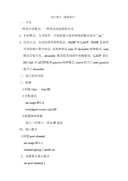
四、端口聚合
1.创建port-channel
int range f0/1-2
channel-group 1 mode on
2.设置聚合端口模式
int port-channel 1
channel-group 1 mode …..
switchport mode trunk
switchport trunk native vlan ID
五、设置路由
默认路由:ip route 0.0.0.0 0.0.0.0 192.168.10.1。
链路聚合(端口汇聚)配置

链路聚合(端口汇聚)配置Link aggregation (port pooling) configurationPort will converge is more than one Ethernet port group together to form a logical gathering, use pooling for upper entity to more than the physical link within the same group together as a logical link.The port aggregation enables the traffic to be Shared across member ports in the aggregation group to increase the bandwidth. At the same time, a dynamic backup of each member port of the same group increases the reliability of the connection.Based on the IEEE802.3 AD standard LACP (Link Aggregation Control Protocol, Link Aggregation Control Protocol) is a Protocol that implements the Link dynamic convergence and solution pooling. The LACP Protocol USES the LACPDU (Link Aggregation Control Protocol Data Unit, the Link Aggregation Control Protocol Data Unit) and the end-to-end interaction information.After the LACP protocol that starts a port, the port will notify the end of the system priority, system MAC, port priority, port number, and operation Key by sending the LACPDU. To end after received this information, the information compared to other port the saved information to choose the port to gather, thus both sides can be to the port to join or quit a dynamic group consensus.According to the convergence method, the port convergence can be divided into three categories: manual gathering, static LACPpooling, dynamic LACP pooling.Experimental environment: two H3C E126A, ethernet1/0/24, ethernet1/0/23 converge to a link.Manual together:Configuration of the first switch:[H3CA] link - aggregation group 10 mode manual[H3CA] interface Ethernet 1/0/24[h3ca-ethernet1/0/24] port link - aggregation group 10Can not specify a loopback - detection enable port as aggregation group member![h3ca-ethernet1/0/24] undo loopback - detection enable / / close the lookback-detection capability[h3ca-ethernet1/0/24] port link - aggregation group 10[H3CA Ethernet1/0/24][H3CA] interface ethernet1/0/23[h3ca-ethernet1/0/23] undo loopback - detection enable[h3ca-ethernet1/0/23] port link - aggregation group 10[H3CA Ethernet1/0/23]Configuration of the second switch:[H3CB] link - aggregation group 10 mode manual[H3CB] interface ethernet1/0/24[H3CB - Ethernet1/0/24] undo loopback - detection enable[H3CB - Ethernet1/0/24] port link - aggregation group 10[H3CB - ethernet1/0/24] interface ethernet1/0/23[H3CB - Ethernet1/0/23] undo loopback - detection enable[H3CB - Ethernet1/0/23] port link - aggregation group 10[H3CB Ethernet1/0/23]Display relevant information:[H3CB] display link - aggregation summary / / display summary informationAggregation Group Type -- Dynamic, S -- Static, M -- ManualLoadsharing Type: Shar -- Loadsharing, NonS -- non-loadsharingActor ID: 0x8000, 000f-e2a8-2defAL AL Partner ID Select Unselect Share MasterID Type Ports Ports Type Port-- -- -- -- -- -- -- -- -- -- -- -- -- -- -- -- -- -- -- -- -- -- -- -- -- -- -- -- -- -- -- -- -- -- -- -- -- -- -- -- -- -- -- -- -- -- -- -- -- -- -- -- -- -- -- -- -- -- -- -- -- -- -- -- -- -- -- -- -- -- -- -- -- -- -- -- -- -- -- --10 M none 2 0 Shar Ethernet1/0/23[H3CB][H3CB] display link - aggregation interface ethernet1/0/24 / display interface informationEthernet1/0/24:Selected AggID: 10Local:Port - Priority: 32768, Oper key: 1, Flag: 0x00远程:系统ID:0 x0,0000-0000-0000端口:0,端口优先级:0,操作键:0,标志:0x00[H3CB]显示ethernet1/0/23链路聚合接口Ethernet1/0/23:选择AggID:10的地方:端口优先:32768,主键:1,标记:0x00远程:系统ID:0 x0,0000-0000-0000端口:0,端口优先级:0,操作键:0,标志:0x00(H3CB)[H3CB]显示链路聚合详细/ /显示详细信息Loadsharing类型:Shar——负载共享、NonS——非负载共享标记:A——LACP_Activity,B——LACP_timeout,C——聚合,D——同步,E——收集,F——分布,拖欠,H,过期了聚合ID:10,聚合类型:手动,Loadsharing类型:Shar聚合描述:系统ID:000 0 x8000 f-e2a8-2def端口状态:S——选择,U——未选中的地方:端口状态优先级主标志- - - - - - - - - - - - - - - - - - - - - - - - - - - - - - - - - - - - - - - - - - - - - - - - - - - - - - - - - - - - - - - - - - - - - - - - - - - - - - - - -Ethernet1/0/23 S 32768 1 { }Ethernet1/0/24 S 32768 1 { }远程:演员合作伙伴优先级关键系统Flag- - - - - - - - - - - - - - - - - - - - - - - - - - - - - - - - - - - - - - - - - - - - - - - - - - - - - - - - - - - - - - - - - - - - - - - - - - - - - - - - -Ethernet1/0/23 0 0 0x0000,000000000000 { }以太网1 / 24 0 0 0 0x0000,000000000000 { }(H3CB)LACP静态配置及显示信息:[H3CA]链接聚合组10模式静态ethernet1/0/24(H3CA)接口(H3CA-Ethernet1/0/24)端口链路聚合组10不能指定环回检测启用端口作为聚合组成员!(H3CA-Ethernet1/0/24)撤销loopback-detection启用(H3CA-Ethernet1/0/24)端口链路聚合组10:1 - lacp是不允许的端口以太网的远程端ethernet1/0/23(H3CA-Ethernet1/0/24)接口(H3CA-Ethernet1/0/23)撤销loopback-detection启用(H3CA-Ethernet1/0/23)端口链路聚合组10(H3CA-Ethernet1/0/23):1 - lacp是不允许的端口ethernet1/0 / 23的远程端。
- 1、下载文档前请自行甄别文档内容的完整性,平台不提供额外的编辑、内容补充、找答案等附加服务。
- 2、"仅部分预览"的文档,不可在线预览部分如存在完整性等问题,可反馈申请退款(可完整预览的文档不适用该条件!)。
- 3、如文档侵犯您的权益,请联系客服反馈,我们会尽快为您处理(人工客服工作时间:9:00-18:30)。
链路聚合(端口聚合)链路聚合有成端口聚合,断口捆绑,英文名port trunking.功能是将交换机的多个低带宽端口捆绑成一条高带宽链路,可以实现链路负载平衡。
避免链路出现拥塞现象。
通过配置,可通过两个三个或是四个端口进行捆绑,分别负责特定端口的数据转发,防止单条链路转发速率过低而出现丢包的现象。
Trunking的优点:价格便宜,性能接近千兆以太网;不需要重新布线,也无需考虑千兆网传输距离极限问题;trunking可以捆绑任何相关的端口,也可以随时取消设置,这样提供了很高的灵活性还可以提供负载均衡能力以及系统容错。
命令:port-group <port-group-number> mode {active|passive|on}no port-group <port-group-number>功能:将物理端口加入Port Channel,该命令的no 操作为将端口从Port Channel 中去除参数:<port-group-number> 为Port Channel 的组号,范围为1~16;active(0)启动端口的LACP 协议,并设置为Active 模式;passive(1)启动端口的LACP 协议,并且设置为Passive 模式;on(2)强制端口加入Port Channel,不启动LACP 协议。
举例:在Ethernet0/0/1 端口模式下,将本端口以active 模式加入port-groupSwitch(Config-Ethernet0/0/1)#port-group 1 mode active命令:interface port-channel <port-channel-number>功能:进入汇聚接口配置模式命令模式:全局配置模式举例:进入port-channel1 配置模式Switch(Config)#interface port-channel 1Switch(Config-If-Port-Channel1)#Switch1 (Config-Port-Range)#port-group 1 mode activeSwitch1 (Config-Port-Range)#exitSwitch1 (Config)#interface port-channel 1Switch1 (Config-If-Port-Channel1)#Switch2#configSwitch2 (Config)#port-group 2Switch2 (Config)#interface eth 0/0/6Switch2 (Config-Ethernet0/0/6)#port-group 2 mode passiveSwitch2 (Config-Ethernet0/0/6)#exitSwitch2 (Config)# interface eth 0/0/8-9Switch2 (Config-Port-Range)#port-group 2 mode passiveSwitch2 (Config-Port-Range)#exitSwitch2 (Config)#interface port-channel 2Switch2 (Config-If-Port-Channel2)#配置结果:过一段时间后,shell 提示端口汇聚成功,此时Switch1 的端口1,2,3 汇聚成一个汇聚端口,汇聚端口名为Port-Channel1,Switch2 的端口6,8,9 汇聚成一个汇聚端口,汇聚端口名为Port-Channel2,并且都可以进入汇聚接口配置模式进行配置。
方法2:以ON 方式配置Port Channel.配置步骤如下:Switch1#configSwitch1 (Config)#interface eth 0/0/1Switch1 (Config-Ethernet0/0/1)# port-group 1 mode onSwitch1 (Config-Ethernet0/0/1)#exitSwitch1 (Config)#interface eth 0/0/2Switch1 (Config-Ethernet0/0/2)# port-group 1 mode onSwitch1 (Config-Ethernet0/0/2)#exitSwitch1 (Config)#interface eth 0/0/3Switch1 (Config-Ethernet0/0/3)# port-group 1 mode onSwitch1 (Config-Ethernet0/0/3)#exitSwitch2#configSwitch2 (Config)#port-group 2Switch2 (Config)#interface eth 0/0/6Switch2 (Config-Ethernet0/0/6)#port-group 2 mode onSwitch2 (Config-Ethernet0/0/6)#exitSwitch2 (Config)# interface eth 0/0/8-9Switch2 (Config-Port-Range)#port-group 2 mode onSwitch2 (Config-Port-Range)#exit配置结果:将交换机Switch1 上的1,2,3 三个端口依次加入port-group1 后我们可以看到,以on 方式加入一个组完全是强制性的,两端的交换机并不会通过交换LACP PDU 来完成汇聚,汇聚也是触发式的,当敲入将2 号端口加入port-group1 的命令时,1 和2 马上汇聚在一起形成port-channel1,当将3 号端口加入port-group1 时,1 和2 汇聚成的port-channel1 被拆散,马上1,2,3 三个端口又重新汇聚成port-channel1(需要说明的是,当有一个新的端口要加入已经汇聚成功的组时,必须先拆散原先的组,然后再能汇聚成一个新的组)。
结果是Switch1 和Switch2 上的三个端口都以ON 模式汇聚起来,各自形成一个汇聚端口。
总结:1;生成树,STP,主要作用是避免环路,网络中有冗余,经常使用多条链路就会产生环路,广播风暴,网络瘫痪,注意的是涉及网络时候千万不要忘记生成树的启动。
如图3,比如说一般大企业中核心交换机于其他交换机都是两条网线连接,这样其中一条出现错误另一条可以工作,但是如果PC2和PC1通信这样就容易出现环路,产生广播风暴,,生成树可以解决这个问题。
2:链路聚合:它的主要作用就是增加网络带宽,一种是交换机之间,如图二比如说两台交换机设备,用一根百兆网线级联,由于访问两台太大就会产生屏蔽,速度变慢,这个时间就可以使用链路聚合,使用port-group命令,建立链路聚合,多用两条网线连接交换机,并把两台交换机连接的端口各自聚合在一起,能增加网络带宽。
还有一种情况就是,如图一,交换机于服务器之间的链接,比如说一台服务器连接交换机上,如果访问量很大,那么服务器就会承受不了,就可以考虑多按两块网卡,使用链路聚合使两块网卡连接的端口聚合在一起,减轻服务器的负担。
channel-group 1 mode desirable这句意思?channel-group用于将超过一个的交换机互联的端口捆绑到一起,主要用于负载均衡比如sw1和sw2之间相连的端口为19,20sw1(config-if-range)#int rang f0/19 -20sw1(config-if-range)#chsw1(config-if-range)#channel-gsw1(config-if-range)#channel-group ?<1-64> Channel group numbersw1(config-if-range)#channel-group 1 ?mode Etherchannel Mode of the interfacesw1(config-if-range)#channel-group 1 mosw1(config-if-range)#channel-group 1 mode ?active Enable LACP unconditionallyauto Enable PAgP only if a PAgP device is detecteddesirable Enable PAgP unconditionallyon Enable Etherchannel onlypassive Enable LACP only if a LACP device is detected要同时在sw1和sw2上做,时间不能超过一分钟,不然端口会err-disable两边都用on表示不启用标准协议两边用desirable+auto表示用Cisco专有的PAgP (Port Aggregation Protocol)两边用active+passive表示用IEEE校准的LACP (Line Aggregation Control Protocol)其中On+On, Desirable+Desirable/auto, Active+Active/Passive 可以通,其它配置则不能形成正确的portchannel************************************************************* RUNK的具体应用TRUNK(端口汇聚)是在交换机和网络设备之间比较经济的增加带宽的方法,如服务器、路由器、工作站或其他交换机。
这中增加带宽的方法在当单一交换机和节点之间连接不能满足负荷时是比较有效的。
TRUNK 的主要功能就是将多个物理端口(一般为2-8个)绑定为一个逻辑的通道,使其工作起来就像一个通道一样。
将多个物理链路捆绑在一起后,不但提升了整个网络的带宽,而且数据还可以同时经由被绑定的多个物理链路传输,具有链路冗余的作用,在网络出现故障或其他原因断开其中一条或多条链路时,剩下的链路还可以工作。
但在VLAN数据传输中,各个厂家使用不同的技术,例如:思科的产品是使用其VLAN TRUNK 技术,其他厂商的产品大多支持802.1q协议打上TAG头,这样就生成了小巨人帧,需要相同端口协议的来识别,小巨人帧由于大小超过了标准以太帧的1518字节限制,普通网卡无法识别,需要有交换机脱TAG。
TRUNK功能比较适合于以下方面具体应用:1、TRUNK功能用于与服务器相联,给服务器提供独享的高带宽。
2、TRUNK功能用于交换机之间的级联,通过牺牲端口数来给交换机之间的数据交换提供捆绑的高带宽,提高网络速度,突破网络瓶颈,进而大幅提高网络性能。