Honeywell Video Blox视频矩阵控制系统快速安装指南word资料8页
VideoBloxConfig软件配置说明书

VideoBlox Config软件配置说明书目录第一章VideoBlox Config配置软件安装 (3)第二章VideoBlox Config配置软件编程 (4)2.1操作主界面 (4)2.2系统配置 (4)2.3摄像机输入配置 (6)2.4摄像机标题 (7)2.5监视器输出配置 (8)2.6区域切换 (8)2.7群组切换 (9)2.8报警配置 (9)2.9操作员配置 (10)2.10操作键盘设置 (12)2.11定期事件配置 (13)2.12显示信息 (14)2.13 Sequence切换命令配置 (14)2.14 其它控制 (18)在进行操作之前请仔细阅读本手册,本手册说明如何操作及设置V I D E O B L O X 矩阵控制系统。
第一章V I D E O B L O X C O N F I G配置软件安装1.1首先将V I D E O B L O X C O N F I G安装光盘插入到CD-ROM中。
1.2 在VBLOXCFG目录下运行SETUP文件,进入安装程序.1.3 在出现如下屏幕时,先选择欲设定的程序子目录,然后选择安装方式,在对应的图标上用鼠标连击两下开始安装。
1.4 将软件安装到目录C:\Program Files\BETATECH\VBloXCFG,应用程序安装完毕。
按VideoBlox Config配置软件安装结束。
配置软件为硬盘加密方式,需从产品供应商处获取软件许可证号,即可运行配置软件。
运行软件前请确认矩阵与电脑串口正确连接。
第二章V I D E O B L O X C O N F I G配置软件编程2.1操作主界面在程序中运行2.2系统配置1.点击Configure进入系统配置;系统配置重新设置同步时间设置配置密码高级配置2.点击Communications键进行串口通信设置;设置矩阵ID号注意:矩阵ID必须设置不为0的编号(对单机箱时)。
3.点击Advanced将许可证号输入。
VIDEOBLOX矩阵培训资料-应用调试快速指南

PB 12 3 456 78 9 0 Enter
Master口,㈠ ,DB9
RS422 Master
Master口,㈠ 1 Tx2 Tx+ 3 Rx+ 4 Rx5 GND 6 DC+ 7 预留 8 预留 9 DC GND
Slave口,㈡ Rx- 1 Rx+ 2 Tx+ 3 Tx- 4 GND 5 DC+ 6 预留 7 预留 8 DC GND 9
SW/1、3、4、5 ON,2、6、7、8OFF(设置波特率为19200B) SW/1-7(地址码),8ON(代表为松下协议) 需要两次复用拨码,中间需要通电重启 SW2/1 OFF,2、3、4ON
问题解答
VIDEOBLOX 矩阵
软件设置快速指南
系统设置——软件注册
• 矩阵的配置软件需要进行注册,方可以具备上载矩阵数 据的功能。
功能键
摇杆方向
功能键
摇杆方向
Up Arrow
反向
Down Arrow 正常
- 键盘独自控制快球(不经过矩阵):功能键为“Store”+“0”,进入
“Stand Alone” 模式
矩阵控制快球连接示意图(总线型)
要求在RS485总线线路 的首尾两端连接末端电 阻,总线距离不能超过 设置——通信设置
• 如果需要使得系统正常的开通,必须要求软件通信设置 的正常,其中主要包括机箱地址、通信波特率等。我们 建议用户机箱地址为1,通信波特率为19.2KB。
系统设置——其他
系统恢复出厂默认值 系统状态诊断 PC与矩阵时间同步
软件登录密码设置
矩阵时间格式设置
输入设置——基本设置
• 通过软件设置, 可以定义视频输入的逻辑地址(键盘上 的编号);物理地址(矩阵上的实际端口地址);前端 类型(固定摄像机或快球)……
霍尼韦尔 通信HREP 4-, 8-, 16-Channel Color DVR快速安装指南说明书
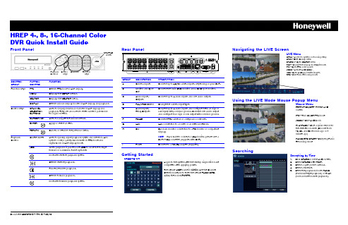
Document 800-07015 – Rev B – 09/10HREP 4-, 8-, 16-Channel Color DVR Quick Install GuideFront PanelCONTROL GROUP BUTTON/CONTROLFUNCTIONFunction KeysPTZ Selects PTZ mode in Live display. MENUDisplays the SETUP menus.SEARCH Displays the SEARCH menu.DISPLAYSelects various display modes in Live display and playback Control KeysCHANNEL SELECTION BUTTONS Used to display individual channels in Live display and playback. They are also used to enter numeric passwords for logon screens.CURSOR KEY Used to navigate the various menus. ENTER Apply or select an item.RETURNCancel, or return to the previous menu.Playback ControlShuttle WheelUsed to quickly adjust playback speed and direction. Also used to control camera zoom when in PTZ mode and digital zoom in Live display mode.JOGWhen playback is paused, use JOG to move the footage forward or backward, frame by frame.JOGSHUTTLE WheelFunction KeysChannelsControl KeysPlayback Controls Rear PanelGetting StartedGROUP CONNECTION DESCRIPTIONACamera Inputs Connect up to 4/8/16 camera inputs, depending on your DVR.B Monitor and Spot OutConnect the main BNC monitor and a BNC spot monitor.C Audio Inputs/OutputsConnect up to 4 audio inputs and one audio output. D PAL/NTSC Switch Change the camera input type.EAlarm Inputs/Relay Outputs Connect up to 4 alarm inputs and configure them as high or low inputs with common ground. Connect one alarm output and configure it as high or low output with common ground. F RS485Connect PTZ cameras or a keyboard controller.G LAN LAN connection to a router or an internal network.HDVIDVI main monitor connection to a PC monitor or compatible display.NoteIf you want to connect a VGA monitor, please use aDVI-to-VGA converter (supplied with DVR).I PowerConnect to a 12V/5A adapter (supplied).Logon to the system after the startup diagnostics have completed after applying power.The default USER name is ADMIN . Use the Channel Selection buttons to enter the default PASSWORD, 1234, then click ENTER .Logging OnNavigating the LIVE ScreenUsing the LIVE Mode Mouse Popup MenuSearchingLIVE MenuMENU - Access to system or recording setup ARCH - Enter Backup menuSEARCH - Open SEARCH menuDISP - Change the display mode/Split mode.PTZ - Open PTZ control panel ZOOM - Activate LIVE ZOOMLOG - Open LIVE Log list with images. REC - Start Panic Recording mode.Mouse MenuFREEZE ON/OFF - Freeze LIVE screenPTZ - Turn On/Off PTZ mode ZOOM - Start LIVE zoomPLAYBACK - Start a quick search for the selected channel (Choose from 10, 20, and 30 seconds ago or 1 minute ago)PANIC REC START - Start/stop Panic Recording modeSearching by Time1.Click SEARCH on the LIVE screen.2.Select SEARCH BY TIME .3.Select a date on the calendar.4.Select a timeline.5.Select the playback mode: PANO (thumbnail-style playback) or PLAY (normal multi-channel playback).+TV (North America only)************************Document 800-07015 – Rev B – 09/10© 2010 Honeywell International Inc. All rights reserved. No part of this publication may be reproduced by any means without written permission from Honeywell. The information in this publication is believed to beaccurate in all respects. However, Honeywell cannot assume responsibility for any consequences resultingfrom the use thereof. The information contained herein is subject to change without notice. Revisions or neweditions to this publication may be issued to incorporate such changes.Playback ControlPlayback ControlsA DISPLAY - change multi-view modeB Playback ControlsC BACKUP - start backup/archive to external deviceD RETURN - exit from playback mode ETime indicatorA B C D ESearching by Event1.Select SEARCH BY EVENT .2.Select search event categories for the search.3.Set a search START/END time.4.Click SEARCH .5.Double-click an event in the search query results list to play that clip.Archiving Searched Video1.Click SEARCH on the LIVE screen.2.Search for recorded video by either searching by Date/Time or searching by Event.3.Select a starting point for playback,click Playto find the beginning of the clip you want to archive, then click Pause to pause playback.4.Click to mark the beginning of thevideo you want to archive.5.Enter a TAG name, select the camerasyou want to archive, then click START . The display returns to playback.6.Click Pause to pause playback, click, then click STOP to mark the end of the clip.7.Click RESERVE , then click CLOSE .8.Click to exit playback mode, thenclick CLOSE to exit the SEARCH menu. 9.Click on the main menu. 10.Click RESERVED DATAMANAGEMENT , select the clip by name in the AVI ARCHIVE LIST, then click BURN .11.Select a DEVICE and a BURNINGTYPE, then click START .Archiving Video from the LIVE ScreenSystem SetupRECORD Menu SetupConfiguring the Network IP Settings1.Click ARCH on the LIVE screen.2.Select NEW ARCHIVE .3.Set the START/END time for archiving.4.Click QUERY .5.Check the data size and select the device to which the data is saved (CD, DVD, or USB media).6.Enter a TAG NAME to name the folder on the device.7.Click BURN to burn the clip to the chosen media.8.Select a DEVICE and a BURNING TYPE, then clickSTART.234557Changing the OSD Language1.Click MENU .2.Select SYSTEM SETUP .3.Select DISPLAY .4.Select OSD .5.Select the desired language.6.Click APPLY .Configuring Recording ParametersTo change the recording configurations from the default settings, select RECORD SETUP , then make the desired changes. Refer to your HREP4, HREP8, HREP16 User Guide.1.Select NETWORK on the MAIN menu.2.Uncheck DHCP for static IP setting.3.Enter the IP information that you get from your network administrator.4.Check the service ports for WEB and RTSP (2 ports only).e AUTO PORT when your router supports UPNP.6.Click AUTO PORT to see theconnection address in the ALIAS field.NoteThe default IP setting is DHCP, so you do not need to manually set the IP address. Your router will assign the IP address automatically.DDNS Settings34For information about configuring the DDNS settings, please refer to the DDNS Application note (document 800-07045).2Connecting through the InternetFor connecting through the internet, the 554 and 8080 ports should be set to Port Forwarding at the router.1.Open Internet Explorer.2.Enter the IP Address or the URL of your DVR into the IE Explorer Address bar:•http://XXX.XXX.XXX.XXX •http://XXX.XXX.XXX.XXX:PPPP} (if you are using another Web port)(PPPP = the assigned web port number)3.Enter the Default ID (ADMIN ) and password (1234), then click OK .4.Allow ActiveX to download.Note If you cannot download ActiveX, then go to the Security tab in IE and check all ActiveX options. 5.Install ActiveX.The LIVE view window opens.In addition to LIVE view, users can access SEARCH and SETUP, depending on their User Authority privileges. Refer to your HREP4,HREP8, HREP16 User Guide for more information about User Authority.。
Honeywell 30 系列网络摄像录制器快速认证安装指南说明书

In the login window, enter your username and password.Follow the on-screen instructions to install the plugin.HN300401xx /HN300802xx /HN301602xx Network Video Recorder Quick Certificate Installation GuideBefore logging in, make sure you have finished the initial setup of yournetwork vidoe recorder. You can refer to NVR Quick Installation Guideor NVR Quick Networking Guide for more information.Thank you for purchasing a Honeywell 30Series NetworkVideo Recorder. The NVR uses HTTPS, a secure communication protocol that verifies the identities of visited websites and servers and encryptsdata exchanged between the client and the server.When you log in to the NVR web client for the first time, some browsersmay display a warning that the connection is not private/secure.To access the web client, you must install a Honeywell-signed securitycertificate.The installation of the security certificate involves three sets of steps:Logging inDownloading the root certificateInstalling the root certificateClick Proceed to 192.168.1.108 (unsafe).Logging in+1 800 323 4576 (North America)+971 44541704 (Middle East)+44 8448 000 235 (Europe)Document 800-25991V1– Rev A – 01/2021 © 2021 Honeywell International Inc. All rights reserved. No part of this publication may be reproduced by any means without written permission from Honeywell. The information in this publication is believed to be accurate in all respects. However, Honeywell cannot assume responsibility for any consequences resulting from the use thereof. The information contained herein is subject to change without notice. Revisions or new editions to this publication may be issued to incorporate such changes. For patent information, see /patent /Open your browser and enter the NVR’s IP address in the address bar.If you are using Chrome, a message appears warning that the connection is not private. Click Advanced.4。
霍尼韦尔矩阵VIDEOGUI操作手册
霍尼韦尔矩阵VIDEOGUI操作手册视频矩阵图形用户接口VideoGUI用户手册版本 1.01 – 22 July 19991. 概述 (3)2. 操作环境需求 (3)2.1.硬件需求 (3)2.2.软件要求 (3)3. 安装 (3)3.1.取得系统解锁密码 (4)3.2.设置操作参数 (4)4. 用户操作 (4)4.1.启动程序 (4)4.2.选择输出监视器 (4)4.3.选择摄像机视频输入 (4)4.4.控制云台摄像机 (4)4.5.控制VCR (5)4.6.控制矩阵 (5)4.7.打开新的显示区域/关闭显示区域 (5)4.8.打开/关闭显示站点 (5)4.9.设置操作参数 (5)5. 配置 (5)5.1.进入配置模式 (5)5.2.添加位图、媒体文件和图标 (5)5.3.修改图标参数 (6)5.4.添加区域 (6)5.5.添加站点 (6)1. 概述Betatech VideoGUI 软件可以让您在PC上以图形界面控制Betatech VideoBloX矩阵。
为适用不同的需求可以设置多种不同的显示。
2. 操作环境需求2.1. 硬件需求安装VideoGUI软件的PC硬件要求如下:2.2. 软件要求PC 上必须装有32位Windows操作系统,可以是 Windows 95, Windows 98 或者 Windows NT。
对于有多个GUI 工作站的系统,需通过网络操作,所以需要安装TCP/IP协议,网络系统同时需要Betatech CCTV Server 软件包。
软件可以适用不同的图形格式:.BMP、.WMF、Windows 增强媒体格式,最简单的作图工具是Windows本身附带的画笔工具,其他象Corel Photo Paint 或 Photo Express都可以用。
软件采用Paradox 7 数据库格式储存视区和站点的数据,进一步的数据库工作需要使用相应的数据库工具。
3. 安装在光驱里放入光盘,运行VideoGUI子目录中的“Setup.exe” 程序,若使用软盘装在软件,安装方法一样,只是要注意更换软盘。
霍尼韦尔 Honeywell安防系统安装和设置指南

Honeywell安防系统配置指南

门禁控制器 (N-1000-III)
门禁控制器 (N-1000-IV)
门禁控制器 (N-1000-IV)
最多不超过31个,总长不超过1200米
Honeywell安防系统配置指南
门禁控制器的配置-PW2000
门禁电脑 串口 通信转换器
(Winpak Pro)
PW-485-PCI-B
RVVP0.5 x 2
Honeywell安防系统配置指南
Ademco大型报警系统配置指南
被动红外探测器探测范围的界定?
W
L 顶视图
Honeywell安防系统配置指南
侧视图
Ademco大型报警系统配置指南
如何选择探测器? 我们通常所述的探测范围 L x W,就如上图中的描述,如:
DT7225: 7.6x9米 DT7235: 11x11米 DT7450: 15x18米
副控键盘:
AVBPCKND:无显示 AVBPCK:无操纵杆 AVBPCKZ:内置操纵杆 AVBPCKC:内置操纵杆、16功能键 AVBPCKA :内置操纵杆、16功能键、喇叭
是
需要控制球机吗?
PIT422
是
需要Vista-120连动吗?
PIT232/232
Honeywell安防系统配置指南
摄像机配置指南—固定球机
每
4297延伸器
台
之所最
和有多
4297延伸器
不4并 超接 过2 8
1
1 9个
274
2
0
前 面
2
0 多
0距9 米离 7
,
总
线
4297延伸器
4297后面距离前所述不超过1200米
Honeywell安防系统配置指南
闭路电视监控系统操作使用手册

项目名称:重庆移动智能化系统用户操作手册编制单位:IBM 上海国际商业机器工程技术有限公司矩阵切换器 操 作 使 用 手 册目录第一章Honeywell VideoBlox矩阵控制键盘操作说明 (4)1.1Keyboard Functionality(键盘功能性) (4)1.2登录模式 (4)1.3监视器、摄像机切换 (5)1.3.1选择监视器 (5)1.3.1选择摄像机 (6)1.4云台摄像机或高速球型摄像机(PTZ) 模式控制 (6)1.4.1操纵杆控制云台摄像机或高速球型摄像机 (6)1.4.2功能键控制云台摄像机或高速球型摄像机 (7)1.5常见故障解决方式 (7)1.5.1键盘无任何显示 (7)1.5.2密码无法登陆 (8)1.5.3有些摄像机或监视器不能切换 (8)1.5.4键盘无法登陆到矩阵,按键没反应 (8)第二章Honeywell VideoGUI视频矩阵图形控制软件操作说明 (9)2.1用户操作 (9)2.1.1启动程序 (9)2.1.2选择输出监视器 (11)2.2常见故障解决方式 (12)2.2.1密码无法登陆 (12)2.2.2对有些摄像机或监视器不能切换 (12)2.2.3系统无法登陆到矩阵,打开软件无法与主机进行通讯 (12)第三章Honeywell数字硬盘录像机操作说明 (13)3.1数字硬盘录像机操作说明 (13)3.2控制台管理软件操作说明 (13)3.3数字硬盘录像机中心控制软件操作说明 (15)3.4常见故障解决方式 (16)3.4.1若操作系统为WINDOWS98,应注意哪些方面? (16)3.4.2检测不到硬盘 (16)3.4.3录像时间不能正常控制 (16)3.4.4录像时录像指示灯一会儿亮一会儿灭? (16)3.4.5录像机散热问题 (17)3.4.6监视器上某一路视频信号不显示 (17)3.4.7通过遥控器无法进行操作,但监视画面正常,面板控制也正常 (17)3.4.8无法进行网络登陆 (17)3.4.9为什么通过客户端程序连接到主机后,监看实时图像时在开始的一段时间内,画面质量较差,有时有拖痕? (17)3.4.10不能定时录像 (17)第一章Honeywell VideoBlox矩阵控制键盘操作说明1.1 Keyboard Functionality(键盘功能性)键的操作是不同的,这取决于KEYBOARD MODE(键盘模式)。
- 1、下载文档前请自行甄别文档内容的完整性,平台不提供额外的编辑、内容补充、找答案等附加服务。
- 2、"仅部分预览"的文档,不可在线预览部分如存在完整性等问题,可反馈申请退款(可完整预览的文档不适用该条件!)。
- 3、如文档侵犯您的权益,请联系客服反馈,我们会尽快为您处理(人工客服工作时间:9:00-18:30)。
VideoBloX快速安装指南20191.1快速安装手册目标配置一套完整的CCTV系统:•固定摄像机•监视器•快速球机– Orbiter 或 Rapid球机•报警输入/输出板切换摄像机到监视器控制快速球机创建由报警输入引起的事件设备矩阵VideoBlox•配有CPU卡的矩阵箱(4U,8U或12U),视频输入模块和视频输出模块(带标题)•报警模块•用于控制球机的协议转化器 AVBPIT422 PIT•带操纵杆的键盘 AVBPCKZ配件•监视器(2)•固定摄像机(2)•快速球机(1)(Orbiter或Rapid球机)•24 V AC 电源配置电脑•有效串口第一步–连线摄像机1.)给摄像机上电,连接视频线到视频输入模块的输入1,2,3。
2.)确保球机的地址是#N,并且连接到视频输入模块的输入#N。
监视器1.) 给监视器上电,将监视器的输出连接到视频输出模块的输出#12.) 连接第二个监视器的输出到CPU 模块的视频输出口上。
第二个监视器的顶部中间将会显示[0]。
如果没有,检查机箱和监视器电源;重新连接CPU BNC 口的同轴电缆。
第二步–设置拨码开关S1S2S3S4第三步 – 诊断监视控制按钮1.) 在CPU 模块的前面板上有四个按钮。
在诊断模式的菜单显示下,可用它们进行选择控制。
2.) 右边最远的按钮(下标箭头)是页面顺序切换按钮。
3.) 右边第二个按钮(上标箭头)是页面倒序切换按钮。
通信页面1.) 用右按钮切换到第二页“Communications”2.) 在此可以查看各个端口的波特率第四步 – 连接配置电脑连接VideoBloX CPU 模块1.) 用9-针母头到9-母头的电缆连接配置电脑串口到CPU 模块的“RS232 Slave ”口(针到针)。
从背后看,左边第一个口为“RS232 Slave ”。
GUI 控制、编程PC 与矩阵连接:将厂家的原配DB9(公)线缆剪掉6、9脚的连线方可连接。
安装VideoBlox 配置软件将配置软件安装到配置电脑上。
1.) 查找、打开“VbloxCFG ” 文件夹2.) 运行“setup.exe”程序3.) 增加VbloxCFG 程序的快捷方式到电脑桌面上。
11023456789运行配置文件1.)运行VideoBlox配置文件2.)点击配置按钮3.)主配置界面将被显示–注意界面左上方的窗体是红色或绿色。
4.)如果窗体是绿色–代表通信连接正常。
5.)如果窗体是红色,通信不正常,检查设置的波特率和通信端口。
6.)在诊断界面上可查看波特率的值。
7.)通信口的停止位为1,如果连接正确,界面左上方的窗体将变成绿色。
第五步–连接键盘1.)用9-针公头到9-针公头(针到针)的电缆连接键盘到VideoBlox CPU模块的“RS422 M aster”口。
2.)键盘一上电就会显示设置的键盘地址和波特率。
(默认值19,200Baud)3.)如果波特率需要更改,那么:•移走电缆•同时按下“S tore Key”和“User Key”,连接电缆。
•User Key 1 – 1200 Baud•User Key 2 – 9600 Baud•User Key 3 – 19,200 Baud (Default)•User Key 4 – 57,600 baud4.)设定键盘地址为1。
更改键盘地址:•移走电缆•同时按下“S tore Key”和数字键,连接电缆。
默认地址为1。
第六步–登陆键盘在系统运行时,操作员要进行操作,必须先登陆键盘 - 这里需要密码,它是在配置程序中进行设置。
配置密码从配置程序–进入“User”设置界面From the Configuration Program – go to the tab Users •配置用户1•选中“Enable”•选择有效日期•点击“S et Password”,设置密码,退出。
•点击“Camera”–选择用户所能控制的摄像机。
•点击“Monitor”–选择用户所能控制的监视器。
•点击“keyboard”–选择用户所能登陆的键盘。
•设定用户权限•点击“Download”发送配置信息给CPU 模块。
退出键盘•按“L og In/Log Outkey”键•输入密码•点击“E nter”键。
第七步—摄像机、监视器的切换选择监视器•Press the Monitor key and press the Enter key按下“Monitor”键,再按“ENTER”键。
•系统现处在监视器模式- 按下数字键选择监视器,也可以用“Next”和“Previous”键选择摄像机•按“Camera”键,然后按“Enter”键。
•系统现处在摄像机模式-按下数字键选择摄像机,•也可以用“Next”和“Previous”。
第八步–连接一体化快球通过协议转换器,将一体化快球连接到系统。
协议转换器可以将VideoBlox 协议转换成相应的协议。
球机设置:RS422 设置PITPelco协议设置:P-D协议2400bps控制电缆连接图:连接电缆1.)用9针公头到9针公头(针到针)的线缆将PIT的“Slave”口和VideoBloX CPU的“RS422 Master”口连接起来。
2.)用9针公头的串口连接PIT的“Master”口的Pin1和pin2。
Pin1连接一体化球机的Data(-);Pin2连接一体化球机的Data(+)。
软件配置在配置程序中,点击“Inputs”•在“Input Number”处,选择摄像机序号为:1。
•在“Physical I/P”处,选择摄像机的物理地址为:1。
•在“Type”处,选择摄像机的类型为:PTZ。
•配置“Pan/Tilt/Zoom”地址为:1。
•点击“Download”下载配置信息。
第九步–一体化球机的控制现在一体化球机的连接和配置已经完成,可通过键盘进行控制。
特殊功能键在摄像机模式中—可以用分控的功能键对一体化球机进行控制和调节。
•Zoom + 放大•Zoom –缩小•Focus + 焦聚放大•Focus –焦聚缩小•Iris + 光圈放大•Iris –光圈缩小第十步–一体化球机预制位一体化球机设置预制位查看预制位的保存•用操纵杆移动一体化球机到需要设定的位置。
•按下“Store ”键后;•再按下数字键;•按下“Enter”键。
•重复1—4步,设置其它预制位。
预制位的调用•按下“Recall”键•再按下需要调用预制位相对应的序号。
•按“Enter”键Honeywell 高速一体化球型摄像机的控制指令本设置针对HDC-251PXVB控制矩阵的PIT设置为Pelco—D协议,摄像机的菜单调用:控制杆向右为进入子目录,向上或向下为光标的移动,向左为推出该条指令。
在字符标示设定中,旋转变速杆为字符翻页设置。
预置位95:调用摄像机的根目录,在某些指令中为确认键(如设置摄像机的花样翻转时,重新调用预置位95时,开始启动设置。
)预置位60: 8条摄像机水平扫描设置;预置位61~68:摄像机水平扫描调用(如调用61为该摄像机的第一条水平扫描指令。
)预置位81~84:自学习花样巡航扫描的调用(如调用81为该摄像机的第一条自学习花样巡航扫描指令。
)预置位70: 8条摄像机预置位的巡航路线设置。
预置位71~78:摄像机预置位的巡航扫描调用(如调用71为该摄像机的第一条巡航扫描指令。
)预置位93:预置位的设置,也可通过矩阵键盘的Store+数字键进行预置位的保存。
对某些厂家的Pelco—D的摄像机先调92 号预置点然后Store92预置点为设左限位,调93 号预置点然后Store92预置点为设右限位,调97 号预置点为启动左右扫描,调96 号预置点为停止左右扫描。
第十一步—安装报警终端盒Video BloX 系统所带的报警终端盒是一个带扁平电缆的不锈钢盒。
•支持32个报警输入•支持4个报警输出安装•用扁平电缆将报警终端盒,连接到VideoBloX CPU上。
•连接一个拨动开关或报警设备到输入#1。
•连接一个驱动的设备(灯或喇叭)到继电器输出的公共端和常开端,并提供适当的电源。
简单的报警顺序配置我们现在配置一个简单的顺序控制(事件/响应)当第一个报警输入#1闭合的时候,继电器输出#1的常开触点闭合。
当第一个报警输入#1断开的时候,继电器输出#1的常闭触点打开。
从配置程序—进入到“Alarms”项•点击“Alarm Inputs”按钮•在“1 to 16”和“17 to 32”处,选择“Local”—它表示报警终端盒的报警输入为:1-32。
•关闭窗口。
•选择报警输入#1,选中“check”选项。
•到常开选择区域,选中“check”选项。
•选择顺序控制#2•到常闭选择区域,选中“check”选项。
•选择顺序控制#1。
•点击“Download”按钮,下载配置信息到CPU。
从配置程序—进入“Sequence”项•选择顺序控制#1•点击“Edit”按钮•编辑窗口将被打开•点击创建按钮—一条结束语句就被插入•点击“+”按钮—增加一条空的语句。
•点击命令下拉菜单,选择“OUTPET”,填写相应参数。
•“1”代表— On•“0”代表—Off•点击“Download”下载配置信息到CPU重复上述步骤设置顺序#2测试•触发报警输入#1,观察继电器输出状态矩阵与矩阵连接(线缆连接):远程矩阵本地矩阵矩阵与矩阵连接(光纤连接):详细软件配置参照VideoBlox Config软件配置说明书.doc。