高精度程控电阻软件使用手册
程控电阻箱选型手册V1.1

YQIAE
YQPCR-B2UKP 系列程控电阻卡
概述
选型
型号 YQPCR-B2UKP(A) YQPCR-B2UKP(B) YQPCR-B2UKP(C) YQPCR-B2UKP(D)
YQPCR-B2UKP 系列程控电阻卡是基于 USB 总线 通讯接口控制的便携式程控电阻卡。
以在加载交流信号时需要注意信号的频率不能太高。 切换开关控制程控电阻输出电路模型如下所示:
A
R
S
SB
B A
R
S
A
B
SA
B
R
A型连接
B型连接
C型连接
A 型连接用于电磁继电器控制电阻输出的程控电阻箱。B 型连接和 C 型连接用于半导体隔离开关控制电阻输
出的程控电阻箱/卡。
三种连接方式的主要区别:
A 型连接和 B 型连接线电阻为恒定值,适用于输出更稳定的电阻信号。C 型连接线电阻是变化的。
程控电阻箱 驱动光盘 电源及信号电缆 用户手册
西安燕秦工业自动化工程有限公司
地址: 陕西省西安市阎良区国家航空产业园蓝天路 5 号碧水蓝庭 14-1-317
电话: (029)86830064
传真:
Xi`An YanQin Industrial Automation Engineering Co., Ltd.
C 型连接的程控电阻箱/卡设备体积和功耗小于 A 型连接和 B 型连接的程控电阻箱/卡。
在选型时需要根据具体的使用环境进行程控电阻箱/卡选择。
西安燕秦工业自动化工程有限公司
地址: 陕西省西安市阎良区国家航空产业园蓝天路 5 号碧水蓝庭 14-1-317
电话: (029)86830064
新型福克火电阻 multimeter 用户操作说明书

new version of the popular Fluke 87 DMM, the 87V,incorporates a selectable low pass filter* that allows for accurate drive output meas-urements that agree with the motor drive controller display indicator. Now, technicians won’t have to guess whether the drive is operatingcorrectly and delivering the correct voltage, current or frequency for a given controlsetting.Troubleshooting philosophyTechnicians use many different methods to troubleshoot an elec-trical circuit, and a good trou-bleshooter will always find the problem — eventually. The trick is tracking it down quickly and keeping downtime to a minimum.The most efficient trouble-shooting procedure begins at the motor and then works systemati-cally back to the electrical source, looking for the most obvious problems first. A lot of time and money can be wasted replacing perfectly good parts when the problem is simply a loose connection.Multimeter measurements on adjustable speed drives utilizing the new Fluke 87V DMMApplication NoteAs you go, take care to take accurate measurements. Nobody takes inaccurate measurements on purpose, but it’s easy to do,especially when working in a high energy, noisy environment like an ASD.Likewise, choosing the right test tools for troubleshooting the drive, the motor, and the con-nections is of utmost importance.This is especially true when tak-ing voltage, frequency and cur-rent measurements on the output side of the motor drive. But until now, there hasn’t been a digital multimeter on the market able to accurately measure ASDs. Fluke’sIntroductionIn the past, motor repair meant dealing with traditional three-phase motor failures that were largely the result of water, dust, grease,failed bearings, misaligned motor shafts, or just plain old age. But motor repair has changed in a big way with the introduction of electronically controlled motors, more commonly referred to as adjustable speed drives (ASDs). These drives present a unique set of measurement problems that can vex the most seasoned pro. Thanks to new technology, now for the first time you can take accurate electrical measurements with a DMM during the installa-tion and maintenance of a drive and diagnose bad components and other conditions that may lead to premature failure.*Patent pendingDrive measurementsInput side measurementsAny good quality true-rms multimeter can verify proper input power to an ASD. Theinput voltage readings should be within 1 % of one another when measured phase to phase with no load. A significant unbalance may lead to erratic drive opera-tion and should be corrected when discovered.Output side measurementsOn the flip side, a digital multi-meter can’t reliably read the output side of a pulse widthmodulated (pwm) motor drive,because the ASD applies pulse width modulated non-sinusoidal voltage to the motor terminals. A true-rms DMM reads the heating effect of the non-sinusoidal voltage applied to the motor, while the motor controller’s output voltage read-ing only displays the rms value of the fundamental component (typically from 30 Hz to 60 Hz). The causes of this discrepancy are bandwidth and shielding.Many of today’s true-rms digital multimeters have bandwidths out to 20 kHz or more, causing them to respond not only to the fundamental component, which is what the motor reallyresponds to, but to all of the high frequency components generated by the pwm drive. And if the DMM isn’t shielded for high frequency noise, the drive con-troller’s high noise levels make the measurement discrepancies even more extreme. With the bandwidth and shielding issues combined, many true-rms meters display readings as much as 20to 30 % higher than what the drive controller is indicating.Fluke’s new 87V multimeter,with its newly incorporatedselectable low pass filter, allows troubleshooters to take accurate voltage, current and frequency measurements on the output side of the drive at either the drive itself or the motor terminals.With the filter selected, the 87V readings for both voltage and frequency (motor speed) should agree with the associated drive control display indications, ifavailable. The low pass filter also allows for accurate current measurements when used with Hall-effect type clamps. All of these measurements are espe-cially helpful when taking measurements at the motor location when the drive’s dis-plays are not in view.Taking safe measurementsBefore taking any electrical measurements, be sure you understand how to take them safely. No test instrument is com-pletely safe if used improperly,and many test instruments are not appropriate for testing adjustable speed drives. Also make sure to use the appropriate personal protective equipment (PPE) for your specific working environment and measurements.If at all possible, never work alone.Safety ratings for electrical test equipmentANSI and the International Electrotechnical Commission (IEC) are the primary independ-ent organizations that define safety standards for test equip-ment manufacturers. The IEC61010 second edition standard for test equipment safety states two basic parameters: a voltage rating and a measurement cate-gory rating. The voltage rating is the maximum continuous work-ing voltage the instrument is capable of measuring. The cate-gory ratings depict the measure-ment environment expected for a given category. Most three-phase ASD installations would be con-sidered a CAT III measurement environment, with power sup-plied from either 480V or 600V distribution systems. When using a DMM for measurements onthese high energy systems, make sure it’s rated at a minimum for CAT III 600V and preferably for CAT IV 600V/CAT III 1000V. The category rating and voltage limit are typically found on the front panel, at the input terminals.The new Fluke 87V is dual-rated CAT IV 600V and CAT III 1000V.Refer to the ABC’s of DMM Safety* from Fluke for additional information on category ratings and taking safe measurements.*The ABCs of Digital Multimeter Safety can be found at /download/library/1263690_w.pdfOscilloscope view of a pwm motor drive signalTransformer type clamp (i200, 80i-400, 80i-600A)1Connect the clamp to the87V’s common and 400 mAinput jacks.2Select the mA/A ac function.3Place the clamp around each of the input supply phasecables in succession, recording each of the readings as theyare taken. Since these clampsoutput one milliamp per amp,the milliamp readings shownon the 87V display are theactual phase current readingsin amps.Hall Effect type (AC/DC)clamp (i410,i-1010)1Connect the clamp to the87V’s common and V/Ωinputjacks.2Select the 87V’s ac voltage function. 3Press the yellow button to enable the low pass filter. This allows the meter to reject all of the high frequency noise generated by the drive con-troller. Once the low pass filter is enabled, the meter will be in the 600mV manual range mode.4Place the clamp around each of the input supply phasecables in succession, recording each of the readings as they are taken. Since these clamps output one millivolt per amp,the millivolt readings shown on the 87V display are theactual phase current readings in amps.Output voltageTo measure the ac output voltage at either the drive or the motor terminals:1Plug the black test lead into the common jack and the red test lead into the V/Ωjack.2Select the 87V’s ac voltage function.Taking the measurementsNow let’s put Fluke’s new 87V DMM to the test. The measure-ments in the following procedure are designed to be made on a 480 volt 3 phase drive control at the control panel terminal strips,using the 87V. These procedures would also be valid for lower voltage 3 phase drives powered by either single or 3 phase sup-ply voltages. For these tests the motor is running at 50 Hz.Input voltageTo measure the ac voltage supply to the input side of the drive at the drive:1Select the 87V’s ac voltage function.2Connect the black probe to one of the three phase input terminals. This will be the reference phase.3Connect the red probe to one of the other two phase input terminals and record the reading.4Leaving the black probe on the reference phase now move the red probe to the third phase input and record this reading.5Make sure there’s no more than a 1 % differencebetween these two readings.Input currentMeasuring the input current gen-erally requires a current clamp accessory. In most cases, either the input current exceeds the maximum current measurable by the 87V’s current function, or it isn’t practical to “break the cir-cuit” to take an in-line series current measurement. Regardless of clamp type, insure that allreadings are within 10 % of eachother for proper balance.Figure 1.Output voltage reading without using the low pass filter.Figure 2.Output voltage reading with low pass filter enabled.3Connect the black probe to one of the three phase output voltage or motor terminals.This will be the reference phase.4Connect the red probe to one of the other two phase outputvoltage or motor terminals.5Press the yellow button toenable the low pass filter.Now record the reading.6Leaving the black probe on the reference phase, now move the red probe to the third phase output voltage or motor terminal and record this reading.7Make sure that there’s no more than a 1 % differencebetween these two readings(see Figure 2). The readingsshould also agree with thecontroller display, panel if available.8If the low pass filter isn’t enabled, the output voltage readings may be 10 to 30 %higher, as on a regular DMM (see Figure 1).2Select the 87V’s ac voltage function.3Press the yellow button to enable the low pass filter. This allows the meter to reject all of the high frequency noise generated by the drivecontroller. Once the low pass filter is turned on, the meter will be in the 600 mV manual range mode.Motor speed(Output frequency using voltage as a reference)To determine motor speed, sim-ply take a frequency measure-ment while using the low pass filter. The measurement can be made between any two of the phase voltage or motor terminals.1Plug the black test lead into the common jack and the red test lead into the V/Ωjack.2Select the 87V’s ac voltage function.3Connect the black probe to one of the three phase output voltage or motor terminals.This will be the reference phase.4Connect the red probe to one of the other two phase output voltage or motor terminals.5Press the yellow button to enable the low pass filter.6Press the Hz button. The displayed reading in hertz will be the motor speed (see Figure 3). This measurement couldn’t be made successfully without the 87V’s low pass filter (see Figure 4).Output currentAs with input current, measuring the output current generally requires a current clampaccessory. Once again, regardless of clamp type, insure that allreadings are within 10 % of each other for proper balance.Transformer type clamp (i200, 80i-400, 80i-600A)1Connect the clamp to the 87V’s common and 400 mA input jacks.2Select the mA/A ac function. 3Place the clamp around each of the output phase cables in succession, recording each of the readings as they’re taken.Since these clamps output 1 milliamp per amp, the milliamp readings shown on the 87V display are the actual phase current readings in amps.Hall Effect type (AC/DC)clamp (i410,i-1010)1Connect the clamp to the87V’s common and V/Ωinputjacks.Figure 5.Output current reading without using the low pass filter.Figure 6.Output current reading with low pass filter enabled.Figure 3.Output frequency (motor speed) without the low pass filter.Figure 4.Output frequency (motor speed) using the low pass filter.4Place the clamp around each of the output phase cables in succession, recording each of the readings as they are taken (see Figure 6).Since these clamps output 1 millivolt per amp, the millivolt readings shown on the 87-V display are the actual phase current readings in amps. This meas-urement would not be possi-ble without the 87V’s low pass filter (see Figure 5).Precision and safetyAdjustable-speed drives (ASDs)deliver big benefits for industry. They save energy, enable more precise process control and help motorsand equipment last longer. And now,with the new 87V button-controlled filter, technicians can precisely check voltage and frequency on ASD motors and verify that they’re operating properly.In addition to its unique ability to accurately measure ASDs, the Fluke 87V boasts a new thermometer function and provides an important line of defense against workplace accidents. Rated for use in 600 V CAT (category) IV and 1000 V CAT III environments, the 87V is engineered to withstand voltage spikes of 8 kilo-volts and reduce risks related to surges and spikes that can cause arc flashes.DC Bus measurementsA healthy dc bus is a must for a properly operating motor drive. Ifthe bus voltage is incorrect or unstable, the converter diodes or capacitors may be starting to fail.The dc bus voltage should beapproximately 1.414 times the phase to phase input voltage. For a 480 volt input, the dc bus should be approximately 679VDC. The dc bus is typically labeled as DC+, DC- or B+, B-on the drive terminal strip. To measure the dc bus voltage:1Select the 87V’s dc voltage function. 2Connect the black probe toeither the DC- or B- terminal.3Connect the red probe to the DC+ or B+ terminal.The bus voltage should agree with the example mentionedabove and be relatively stable.To check the amount of ac ripple on the bus, switch the 87V’s function switch to the vac func-tion. Some small drives don’tallow external access to the dcbus measurement without disas-sembling the drive. If you can’t access the dc bus, use the peakmin max function on the 87V to measure the dc bus voltage via the output voltage signal.1Plug the black test lead into the common jack and the red test lead into the V/Ωjack.2Select the 87V’s ac voltage function.3Connect the black probe to one of the three phase output voltage or motor terminals.This will be the reference phase.4Connect the red probe to oneof the other two phase output voltage or motor terminals.5Press the MIN MAX button.6Press the7The displayed reading in Peakmin max will be the dc bus voltage.Motor speed(Output frequency using current as a reference)For motors that pull at least 20 amps of running current,motor speed can be determined by taking a frequency measure-ment with current clamps. Until now, noise issues have prevented accurate readings using hall effect type clamps.Here’s how the low pass filter makes it possible.Motor speed using aHall Effect type (AC/DC)clamp (i410,i-1010)1Connect the clamp to the87V’s common and V/Ωinput jacks.2Select the 87V’s ac voltagefunction.3Press the yellow button toenable the low pass filter. This allows the meter to reject allof the high frequency noisegenerated by the drive con-troller. Once the low pass filter has been turned on, the meter will be in the 600 mV manual range mode.4Place the clamp around one of the output phase cables. Verify that the 87V is reading acurrent of at least 20 amps(20 mV in the display).5Press the Hz button. Thereadings now display themotor speed as a frequencymeasurement.Motor speed using atransformer type clamp(i200, 80i-400, 80i-600A)1Connect the clamp to the 87V’s common and 400 mA input jacks.2Select the mA/A ac function. 3Place the clamp around one of the output phase cables. Verify that the 87V is reading a cur-rent of at least 20 amps(20mA in the display).4Press the Hz button. The read-ings now display the motorspeed as a frequency meas-urement.Fluke CorporationPO Box 9090, Everett, WA USA 98206Fluke Europe B.V.PO Box 1186, 5602 BDEindhoven, The NetherlandsFor more information call:In the U.S.A. (800) 443-5853 or Fax (425) 446-5116In Europe/M-East/Africa (31 40) 2 675 200 or Fax (31 40) 2 675 222In Canada (800) 36-FLUKE or Fax (905) 890-6866From other countries +1 (425) 446-5500 or Fax +1 (425) 446-5116Web access: ©2004 Fluke Corporation. All rights reserved.Printed in U.S.A. 6/2004 2155830 A-US-N Rev BFluke.Keeping your worldup and running.。
DO5000系列多功能电阻计说明书

930077930076True 4 terminal measurement eliminates lead resistance errors I I I10micro ohm resolution IMeasuring range from 3 milli ohm to 30kilo ohmIIMeasuring range from 200 milli ohm to 30 kilo ohm I 100 nano ohm resolution I I I True zero capabilities I I I Digital CalibrationI II Open circuit lead warning LED I I I Fast measuring capability of 50measurements per second I I I High Accuracy 0.03%I I I Data logging with statistical analysis I I I Cable length calculations II IRechargeable batteries built inIAutomatic temperature compensation with programmable coefficients I I I Current range from 10mA to 10AIII Current range from 10 micro Ampto 10mAProgrammable measuring current 10% to 100% in 1% steps I I I Programmable High Low Limits with red / green lamps on front panel I I I Open Circuit voltage limit mode 20mV / 50mV maximum I I I Measuring current selection +I / -I and Auto averageI I I D05000 SERIESA COMPREHENSIVE RANGE OF MAINS AND BA TTERYPOWERED DIGIT AL MICRO OHMMETERS WITHTEMPERA TU RE COMPENSA TIONThe D05000 series of digital micro ohmmeters offer flexibility of measurement w ith high accuracy and exceptional functionality. The D0500 series encompass all the features required in an ohmmeter in one practical instrument.This series of instruments have programmable measuring current in 100 steps, ensuring that w e have a model in the range suitable for your application.Automatic temperature compensation references the measurement to 20o C and Hi / Lo limits permits sorting of components with the minimum of fuss. The D05000 series all have the ability to take an external PRT 100 sensor, this is easily plugged into the socket on the front of the unit.All these functions are available as standard as well as a data logging function w hich stores up to 4000 date and time stamped readings. Statistical analysis of these values allows you to display the Max / Min / Average values as well as the peak to peak and standard deviation.The range of D05000 instruments is ideally suited for laboratory testing of samples, production line testing, and w ith the addition of the IEEE-48 or PLC interfaces, the D05000 series may be remotely controlled and integrated into an automated testing system.When the units are used in the fast measuring mode they can easily do 50 measurements per second.These features are available on all of the models in the range.The D05001 only differs from the D05000 in that it can be mains and battery powered. The D05002 has a lower current capability than both of the other models.Bracken Hill, South West Industrial Estate, Peterlee, County Durham, SR8 2SW United KingdomT el:+44 (0) 191 586 3511 Fax:+44 (0) 191 586 0227 Email:*****************Web:M e a s u r e m e n t4 terminal Kelvin/Thomson principle eliminates errors due to lead resistanceD i s p l a yLCD graphics panel with backlit 30,000 count R a n g es8 automatic or manual selection T e r m i n a l s4mm safety socketsW o r k i n g T T e m p e r a t u r e0°C to +45°C rel. humidity 80% max. non-condensing S t o r a g e T T e m p e r a t u r e -20°C to +60°C M a i n s S S u p p l y115/230V +10% -10%47Hz to 163Hz 20VA S a f e t yEN 61010-1 EMC-EN 61236D i m e n s i o n s339mm x 324mm x 131mm (W H D) approx M a s s12kg approx. 12kg packed in carton A u t o Z Z e r oPermits the zero of measurement valuesA v e r a g eAutomatic average and display of measurement with forward and reverse currentA u t o T T e m p e r a t u r e C C o m p e n s a t i o nAutomatically references measurement to temperature of 20°C or user defined temperature. User coefficients may be used.External Pt100 senses temperature manual value can be used H i // L L o L L i m i t sLimit values can be set over entire measurement range C a l i b r a t i o nDigital pass code protectedP r o t e c t i o n415 Vrms maximum at the measuring terminals will blow internal protection fuseD05002 SPECIFICA TIONSCode ItemD05000 series OptionsC02 1 metre cable clamp with metal base for the precise measurement of 1 metre cable samples 0.1…100mm 2C03 1 metre cable clamp with water bath for the precise measurement of 1 metre cable samples 1…1000mm 2C02A 1 metre cable clamp with metal base for the precise measurement of 1 metre cable samples 1…1000mm 2DO500-CS Calibration standardIEEE-DO5Interface IEEE-488 HS02-P Duplex handspikes with 3 and 15 metre lead length HS01-P Duplex handspikes with 3 metre lead length IEEE-L01IEEE-488 cable 1 metreLS03-P Lead set with 3 metre leads terminated in large Kelvin clips type KC3LS04-P Lead set with 3 metre and 15 metre lead length terminated in large Kelvin clips type KC3LS05Lead set with 4 x 1 metre leads terminated in banana plugs, 4 x Crocodile clips, 4 x test probes and 2 x Kelvin clips type KC1LS06-P Lead set with 1 metre leads terminated in miniature Kelvin clips type KC2PLC-DO5Interface PLCPT02-DO5Temperature probe with 2 metre lead lengthPRECISION INSTRUMENTSCROPICO MEDICALRIGEL PORTABLE ELECTRICAL SAFETY INSTRUMENTSSEA W ARD w ard test and measurement companies include:930077930076。
美瑞克RK9930系列程控接地电阻测试仪使用说明书

美瑞克仪器 MEIRUIKE INSTRUMENTManua l使用说明书深圳市美瑞克电子科技有限公司版本历史:由于说明书中可能存在错误或遗漏、改进和完善仪器功能、更新技术及升级软件,本说明书将做相应的调整和修订、不断完善以利于使用。
请关注所使用的软件版本及说明书版本。
2020年5月.................第一版2021年 1月................第二版2021年 3月................. 第三版2021年 7月................. 第四版2021年 9月................. 第五版声明:本公司可能对该产品的性能、功能、软件、结构、外观、附件、包装以及说明书等进行完善和提高,如有修改,恕不另行通知!如造成疑惑,请与本公司联系。
安全警告:仪器接地本仪器为I类安全仪器,连接电源时,请确认电源插座含有接地线。
如未接地,机壳上带有的静电或感应电可能会造成人身伤害!触电危险操作、测试及仪器维护时谨防触电,非专业人员请勿擅自打开机箱,专业人员如需更换保险丝或进行其它维护,务必先拔去电源插头,并在有他人陪同情况下进行。
即使已拔去电源插头,电容上仍可能会有危险电压,应在放电后再行操作。
电击损害测试过程中任何不正确取下或加上被测件的操作都会造成人身、财物或仪器的异常损害由于不正常的操作而造成仪器的损坏,其维修费用由客户负责。
输入电源请按本仪器规定的电源参数要求使用电源,不符合规格的电源输入可能损坏本仪器。
远离爆炸性气体环境电子仪器不可以在易燃易爆气体环境或含有腐蚀性气体或烟尘环境中使用,因为这可能会带来危险。
其它安全事项请不要向本仪器的测试端子施加任何电压源或电流源。
提示对所阐述内容的重要补充或提醒。
目录第一章安全规则1.1一般维护规定 (1)1.2维护和保养 (1)1.3测试环境 (1)1.4操作人员规定 (2)1.5安全接地规定 (2)1.6更换保险丝规定 (3)1.7测试安全规定 (3)1.8测试异常规定 (3)1.9安全要点 (3)1.10测试的重要性...使用者的安全 (3)1.11交流接地电阻测试......................................................3-4第二章概述及技术指标2.1产品概述 (5)2.2技术指标 (6)第三章面板说明3.1前面板结构...............................................................7-83.2后面板结构 (9)3.3屏幕显示区域定义 (10)3.4主菜单按键和相应显示的页面.............................................10-12第四章操作说明4.1开机说明及开机画面 (13)4.2操作步骤...............................................................13-14第五章PLC遥控接口5.1PLC遥控信号 (15)5.2PLC遥控输出信号说明 (15)5.3PLC遥控输入信号说明....................................................15-16第六章参数设置6.1待测模式 (16)6.2参数设置模式 (16)6.3系统设置模式 (16)6.4接地电阻参数说明 (16)6.5系统设置参数说明........................................................17-196.6文件参数说明 (19)第七章远程控制7.1RS232C接口说明 (19)7.2RS485接口说明 (20)7.3USBTMC接口说明 (20)第八章SCPI串口指令参考8.1指令格式简要说明 (20)8.2SCPI指令集 (21)8.3DISPLAY指令集 (21)8.4FUNCTION子系统命令集....................................................21-27第九章维护指南9.1日常维护 (27)9.2简单故障处理 (27)9.3仪器系统软件升级步骤说明 (27)第十章附件及保修10.1附件 (28)10.2保修 (28)第一章安全规则使用手册内容若有改变,恕不另行通知使用手册若有不详之处,请直接与本公司联系测试前应注意的规定和事项!1.1一般规定■使用测试仪以前,请仔细阅读手册,了解操作规程和相关的安全标志,以保证安全。
NS-Scope 示波器程控软件使用手册 高阶版说明书

NS-Scope示波器程控软件-使用手册高阶版纳米软件·智能测试西安天宇微纳软件有限公司目录一、兼容仪器 (1)二、安装声明及仪器连接 (1)1.安装声明 (1)2.安装过程 (1)3.软件卸载 (4)4.软件授权 (4)5.仪器连接 (5)三、软件界面及功能 (6)1.参数规则 (7)2.自动存储 (7)3.参数设置 (7)4.测量项 (9)5.测试过程 (9)6.光标 (11)7.更多功能 (12)8.波形回放 (15)四、联系我们 (15)一、兼容仪器具有U S B、L A N、G P I B任意一种程控接口的示波器,如:泰克PDS1000/2000/3000/5000/7000系列、TPS2000系列、TBS1000/2000系列、D P O2000/3000/5000/7000系列、M S O2000/3000/4000/5000系列、M D O3000系列、M S O4/5/6系混合信号示波器(4通道),是德科技D S O1000/2000/3000/4000/5000/6000/7000/8000/9000系列、MSO2000/4000/6000/7000/8000/9000系列、EDUX1052、54600全系列、54800全系列等。
二、安装声明及仪器连接1.安装声明(1)系统必须是WIN10以上版本,特殊需求请联系客服;(2)安装软件时需要关闭杀毒软件及其他影响安装包运行的软件;(3)上位机软件不能安装在系统盘---C盘。
并且安装盘/驱动器的权限不能被锁死,不能限制读取和写入数据;(4)如果您的系统本身已经安装驱动TekVisa,需要卸载当前系统内的TekVisa以及全部NI软件后再安装,否则会导致不能正常连接仪器;(5)在运行该软件前需另行安装驱动NI-VISA,如您已安装请确认NI-VISA能正确运行;(6)其次根据您的连接方式安装相应的通讯驱动;(7)由于长期采集数据和存储采集到的数据需要10G以上的硬盘容量,因此在安装选择磁盘时需要关注这个需求点,请选择剩余大容量磁盘安装本软件。
HZ1008程控静态电阻应变仪使用说明

HZ 1008程控静态电阻应变仪使用说明书地址:河北省秦皇岛市北戴河区联峰北路56号邮编:066100 电话/传真: (0335)4046907秦皇岛市惠智测控技术开发有限公司目录第一章概述 (1)1.1 特性 (1)1.2 主要技术指标 (1)1.3 仪器面板说明 (2)1.3.1 HZ1008F前面板说明 (2)1.3.2 HZ1008F后面板说明 (2)1.3.3 HZ1008F应变测试接线上面板说明 (3)1.3.4 HZ1008F整机外型示意 (4)第二章仪器组成及结构 (4)2.1 HZ1008F组成及结构示意图 (4)2.2 HZ1008F可配接传感器模块示意 (4)第三章仪器使用及维护 (4)3.1 使用方法 (4)3.1.1 准备工作 (4)3.1.2 组桥连线 (5)3.1.3 应变仪工作模式设置 (6)3.1.4 仪器测量参数设置 (8)3.1.5 测量操作 (9)3.2 使用注意事项 (10)3.3 维护 (11)第四章保修事项 (11)第五章附录 (11)5.1 附件清单 (11)5.2 联系方式 (11)5.3 常见问题及解决方法 (11)第一章概述HZ1008F程控静态电阻应变仪是我公司采用嵌入式MUC控制技术、显示技术、模拟数字滤波技术及串行通信技术等精心设计的一款应变仪。
该静态应变仪能通过配接各种材料力学多功能实验台,完成各理工科大专院校电测法材料力学实验;也可配接各类力传感器、电阻应变式位移计、应变计及应变花等进行各种不同类型的工程测试。
该程控静态电阻应变仪采用8屏LED同时显示8个通道的应变值,显示清晰直观,测试结果一目了然。
仪器平衡采用现代应变测试中常用的预读数法自动桥路平衡的办法,增强学生对现代测试尤其是虚拟仪器测试的基本概念和使用方法的了解。
桥路平衡方式有自动平衡(总清)/单点平衡(单通道清零)两种方式,用户可根据现场情况灵活使用,方式更便捷、使用更方便。
高精度程控电阻软件使用手册

广州虹科电子科技有限公司技术部程控电阻控制软件使用手册版本1.0广州虹科技术部版权所有文档信息作者:韩伟创建日期: 2015-11-24审核者:审核日期:最后修订者:韩伟最后修订日期: 2015-11-27文档类型:软件使用手册文档修订历史版本号修订日期修订者修订内容1.0 2015-11-24 韩伟初始创建目录目录 (1)一引言 (2)1 编写目的 (2)2 软件运行环境 (2)⑴适用运行环境 (2)⑵适用操作系统 (2)⑶配置要求 (2)二软件安装 (3)1 安装步骤 (3)2 环境软件安装 (4)三软件说明 (4)1 软件简介 (4)2 功能介绍 (4)⑴板卡地址设置模块 (5)⑵阻值显示模块 (5)⑶直接设置电阻值模块 (5)⑷编程模块-手动模式 (5)⑸编程模块-自动模式 (5)⑹预设阻值模块 (5)⑺预设阻值载入模块 (6)四测试验证 (6)1 实物测试 (6)2 仿真测试 (8)五注意事项 (11)一 引言1 编写目的本软件有广州虹科电子科技有限公司技术部开发,配套英国Pickering 公司的程控电阻卡40-297-050在LXI 机箱中的使用,实现对六个通道输出电阻值的精确控制以及对板卡各个通道的电阻值输出进行编程。
2 软件运行环境⑴ 适用运行环境运行环境类型Workstation工作站PC桌面电脑Laptop移动电脑虚拟开发环境-VDI虚拟开发环境-RemoteAPPHPC-PBSHPC-WHS⑵ 适用操作系统操作系统WinXP 32bitWinXP 64bitWin7 32bit Win7 64bitLinuxWin10Win Server 2008R2Win Server 2003⑶ 配置要求最低配置要求 建议配置处理器 Intel 赛扬1GHz 处理器2.1GHZ 或兼容处理器内存 512 MB RAM 1G 安装分区大小 20000M 500显示器分辨率 1024*768 1024*768最低设置要求 建议设置 Labview runtime engine2014 2014Java Version 8Version 8 Update 66二软件安装1 安装步骤下面将简单介绍软件的安装步骤。
CS2676CXCX1CX2程控绝缘电阻测试仪说明书
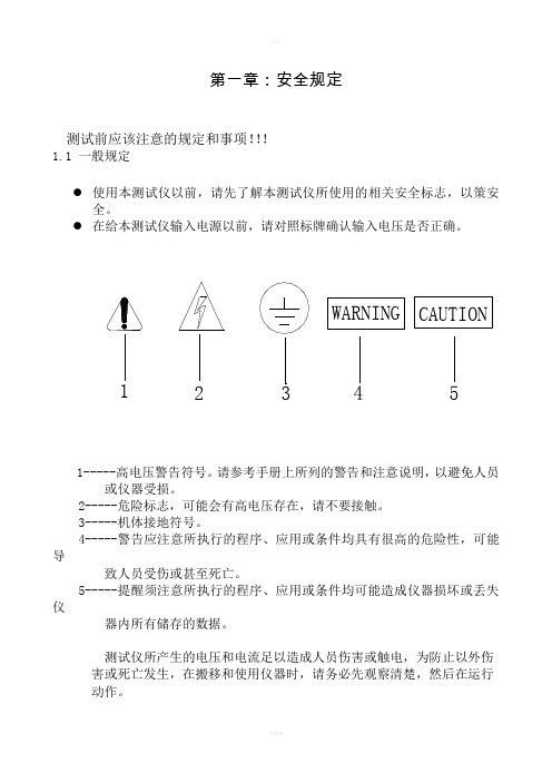
第一章:安全规定测试前应该注意的规定和事项!!!1.1 一般规定●使用本测试仪以前,请先了解本测试仪所使用的相关安全标志,以策安全。
●1-----高电压警告符号。
请参考手册上所列的警告和注意说明,以避免人员或仪器受损。
2-----危险标志,可能会有高电压存在,请不要接触。
3-----机体接地符号。
4-----警告应注意所执行的程序、应用或条件均具有很高的危险性,可能导致人员受伤或甚至死亡。
5-----提醒须注意所执行的程序、应用或条件均可能造成仪器损坏或丢失仪器内所有储存的数据。
测试仪所产生的电压和电流足以造成人员伤害或触电,为防止以外伤害或死亡发生,在搬移和使用仪器时,请务必先观察清楚,然后在运行动作。
1.2 维护和保养1.2.1 使用者的维护为了防止触电的发生,请不要拆开测试仪的箱体。
本系列测试仪内部所有的零件,绝对不需使用者维护。
如仪器有异常情况发生,请与长盛仪器或其指定的经销商联系。
1.2.2 定期维护本系列测试仪的输入电源线、测试线和相关附件等根据使用频段定期要仔细检验和校验,以保护使用者的安全和仪器的准确性。
1.2.3 使用者的修改使用者不得自行更改仪器内部的线路和零件,如被更改,本公司对仪器的保证自动失效并且本公司不承担任何责任。
使用未经长盛仪器认可的零件或附件也不予保证。
如发现送回的仪器被修改,长盛仪器会将仪器的电路或零件修复回原来的设计状态,并收取维修费用。
1.3 输入电源本系列测试仪必须有良好的接地。
测试仪的后面板上有一接地端,请将此接地端子与大地接触良好。
测试仪必须有单独的开关,把此开关安装于特别明显的位置并标明其功用。
一旦有紧急事故发生,可以立即关闭电源,以便处理故障。
本系列测试仪输入电源为AC交流电源。
电源范围为交流(AC)220V±10%,电源频率为50Hz,在该电源范围内如电源不稳定则有可能造成本系列测试仪异常动作或损坏测试仪内部元件。
注意!!!测试仪使用的保险丝为2A快速熔断型。
- 1、下载文档前请自行甄别文档内容的完整性,平台不提供额外的编辑、内容补充、找答案等附加服务。
- 2、"仅部分预览"的文档,不可在线预览部分如存在完整性等问题,可反馈申请退款(可完整预览的文档不适用该条件!)。
- 3、如文档侵犯您的权益,请联系客服反馈,我们会尽快为您处理(人工客服工作时间:9:00-18:30)。
广州虹科电子科技有限公司技术部程控电阻控制软件使用手册版本1.0广州虹科技术部版权所有文档信息作者:韩伟创建日期: 2015-11-24审核者:审核日期:最后修订者:韩伟最后修订日期: 2015-11-27文档类型:软件使用手册文档修订历史版本号修订日期修订者修订内容1.0 2015-11-24 韩伟初始创建目录目录 (1)一引言 (2)1 编写目的 (2)2 软件运行环境 (2)⑴适用运行环境 (2)⑵适用操作系统 (2)⑶配置要求 (2)二软件安装 (3)1 安装步骤 (3)2 环境软件安装 (4)三软件说明 (4)1 软件简介 (4)2 功能介绍 (4)⑴板卡地址设置模块 (5)⑵阻值显示模块 (5)⑶直接设置电阻值模块 (5)⑷编程模块-手动模式 (5)⑸编程模块-自动模式 (5)⑹预设阻值模块 (5)⑺预设阻值载入模块 (6)四测试验证 (6)1 实物测试 (6)2 仿真测试 (8)五注意事项 (11)一 引言1 编写目的本软件有广州虹科电子科技有限公司技术部开发,配套英国Pickering 公司的程控电阻卡40-297-050在LXI 机箱中的使用,实现对六个通道输出电阻值的精确控制以及对板卡各个通道的电阻值输出进行编程。
2 软件运行环境⑴ 适用运行环境运行环境类型Workstation工作站PC桌面电脑Laptop移动电脑虚拟开发环境-VDI虚拟开发环境-RemoteAPPHPC-PBSHPC-WHS⑵ 适用操作系统操作系统WinXP 32bitWinXP 64bitWin7 32bit Win7 64bitLinuxWin10Win Server 2008R2Win Server 2003⑶ 配置要求最低配置要求 建议配置处理器 Intel 赛扬1GHz 处理器2.1GHZ 或兼容处理器内存 512 MB RAM 1G 安装分区大小 20000M 500显示器分辨率 1024*768 1024*768最低设置要求 建议设置 Labview runtime engine2014 2014Java Version 8Version 8 Update 66二软件安装1 安装步骤下面将简单介绍软件的安装步骤。
首先,将压缩包减压后,出现如下的程序:运行setup.exe,出现安装对话框,在对话框里边选择想要安装的文件目录:在这里目录可以由用户自定义,选择完成后点击下一步,再点击下一步,程序开始安装,稍作等待后,程序安装完成,再点击下一步,进入Pickering公司60系列LXI驱动的安装,该驱动为运行LXI系统的必要驱动,所以不建议用户取消,如果不小心取消了该驱动的安装,可以在该网址重新下载驱动进行安装,一路默认安装,在安装完驱动后,重启电脑,便可以使用该软件对LXI机箱中的40-297系列程控电阻进行操作。
2 环境软件安装软件运行需要Labview runtime engine 2014环境的支持,该环境已经集成在程序的安装包中,因此不需要单独安装。
软件需要Pickering的LXI驱动,前文已经介绍,集成于安装文件中。
三软件说明1 软件简介该软件主要用来实现对于高精度程控电阻卡的输出进行精确的控制和读取,以及对输出进行编程,从而实现在测试测量中对于精确电阻值的需求,例如在温控系统中通过对电阻值进行编程实现对于不同温度的模拟,从而达到测试控制器的目的。
2 功能介绍该软件的语言为中文,主面板如图所示:该软件分为如下几个模块:⑴板卡地址设置模块该模块可以设置板卡的具体地址,实现软件与板卡的连接,其中,设备IP 中填写LXI机箱的IP地址,该地址可以在LXI机箱的LED显示屏上找到,也可通过Pickkering的General SFP软件查找,或者通过Find LXI软件进行查找。
板卡具体的总线号与槽位号可以通过后两款软件获得,填写完毕后,点击“开始运行”,则该模块功能锁定,后续对板卡操作的模块激活。
⑵阻值显示模块该模块可以实时显示电阻卡各个通道的电阻值,用户可以轻松了解板卡当前阻值状况。
⑶直接设置电阻值模块单击模块前边的按钮激活该模块,在该模块中,用户可以通过在文本框中输入电阻值来直接对电阻卡的各个通道的电阻值进行设置,输入数字后按回车键或者单击空白处进行确定。
电阻值可以是阻值范围内的任意值,也可以是短路(0)或者开路(inf)。
⑷编程模块-手动模式单击模块前边的按钮激活该模块,在该模块中,用户可以预设多组每个通道的电阻值,包括短路和开路状态,通过“上一组”和“下一组”按钮来进行不同组的切换。
用户也可以直接通过“上一组”和“下一组”按钮中间的空白输入框直接输入自己想跳到的组别。
预设的阻值可以通过软件生成并且导入。
该模块用蓝色数字来显示当前组的阻值,还可以显示出前一组和后一组六个通道的阻值,方便用户观察。
⑸编程模块-自动模式单击模块前边的按钮激活该模块,在该模块中,用户可实现多组电阻值的自动步进变化,在设置完每一组的电阻值以及该组和下一组的延时后,点击“开始”按钮,程序开始运行,电阻值根据设定时间的不同开始步进变化。
同样预设的阻值可以通过软件生成并且导入。
该模块用蓝色数字来显示当前组的阻值,还可以显示出前一组和后一组六个通道的阻值,方便用户观察。
⑹预设阻值模块点击“新建”按钮,即可打开预设阻值模块,如下图所示,在该模块中可输入每一组六个通道相应的阻值,以及在自动模式下使用的步进延时,可以通过“保存”按钮将预设值保存为*.csv格式的文件,供载入模块读取。
⑺预设阻值载入模块该模块可以载入预设模块保存的文件,供编程模块使用,点击地址框后边的文件按钮,即可打开文件选择按钮,选择好保存的文件后,即可载入。
四测试验证软件安装完毕后,有两个方法进行测试和验证,即有实物的实际测试和没有实物的模拟测试。
1 实物测试实物测试就是在有Pickering的LXI机箱以及高精度程控电阻板卡的情况下对整个系统进行测试。
下边是具体的测试过程:①将电阻卡插入LXI机箱,将机箱与控制PC通过网线连接。
②打开电源开关,并且将PC开机。
③等LXI机箱启动后,可以在机箱控制器的显示屏上获取到一个IP地址,如图所示:④在控制PC上打开浏览器,输入获取到的IP地址,即可打开LXI的控制面板,如图所示:⑤点击“Instrument Control”,然后点击右边的“Click here to launch the Javacontrol applet”,即可打开如下面板:如果未能打开,请按照提示安装最新版的JAVA环境,即可打开。
在该界面中,左上角的窗口显示了目前插在机箱中的板卡,而右上角的窗口显示了当前选中板卡的具体信息,在该窗口中我们可以获得电阻卡的总线号(Bus)和槽位号(Device)。
⑥在获取到了板卡的位置信息以后,就可以打开我们的电阻控制软件,输入相应的板卡位置信息,点击“开始运行”,即可开始用软件来实时控制板卡。
2 仿真测试对于身边没有LXI实物的情况下,我们设计了仿真测试,即仿真出一个虚拟的LXI机箱来实现对软件的测试。
这就需要我们自行搭建一个虚拟机箱。
以下是虚拟机箱的搭建方法。
首先需要安装VirtualBox,下载地址:选择下载合适自己系统的最新版并且安装,然后下载Pickering公司的Virtual LXI device ISO,下载地址:下载完成后,打开VirtualBox,选择新建虚拟机,具体设置如下图,类型选择Linux,版本选择Ubuntu(32-bit),设置好后,点击创建,即可创建一个虚拟机。
然后选中虚拟机,点击工具栏中的设置,即可打开设置窗口,在设置窗口中,首先打开“系统”选项卡,然后在“启动顺序”窗口中只勾选“光驱”,如下图所示:然后切换到存储选项卡中,在“储存树”窗口中选择“控制器:IDE”,点击“没有盘片”,可以在右侧的属性栏里看到该控制器分配的光驱,单击选择控制器下拉菜单后边的光盘按钮,载入刚刚下载好的LXI device ISO,即可看到如下图界面::最后切换到网络选项卡,勾选“启用网络连接”,连接方式选择“桥接网卡”,如下图所示:设置完毕后,点击确定保存设置,然后运行虚拟机,就会出现如下界面:这表明我们已经成功的创建了一台LXI虚拟机箱,其中inet addr后边的IP 地址就是机箱的IP地址。
我们用浏览器连接该IP,就会出现LXI的控制面板,与实际机箱的控制面板相同。
点击左下角的Simulation,可以打开仿真机箱的设置界面,在这个界面中可以选择不同的机箱以及板卡。
在选择了正确的机箱和板卡以后,就可以运行软件进行相关功能的测试。
五注意事项i 在设置电阻值的时候不可以超过电阻本来的阻值范围,否则会导致阻值设置不成功,为了防止以外发生,系统锁死,重启后解除。
II 如果因为意外导致程序关闭,重新打开后无法连接到LXI设备,请重启LXI设备。
III 在编程-自动模式运行中切换其他模块时,需要等到自动模式运行结束或者手动按“停止”键停止自动模式的运行。
如果有其他无法解决的问题,请联系我们:广州虹科电子科技有限公司。