Wonderware 培训资料
wonderware ide 培训的手册文档第一章
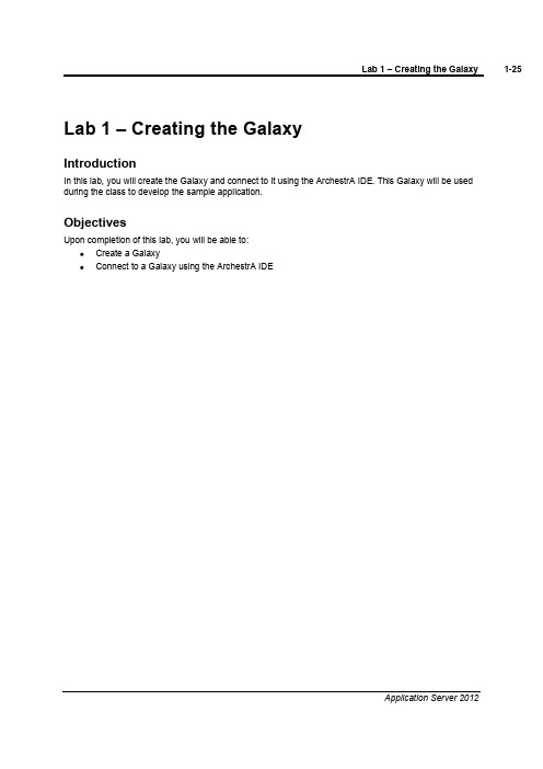
Lab 1 –Creating the GalaxyIntroductionIn this lab, you will create the Galaxy and connect to it using the ArchestrA IDE. This Galaxy will be used during the class to develop the sample application.ObjectivesUpon completion of this lab, you will be able to:Create a GalaxyConnect to a Galaxy using the ArchestrA IDECreate the GalaxyIn the following steps, you will create a Galaxy and connect to it.1.Open the ArchestrA IDE(Start | All Programs | Wonderware | ArchestrA IDE).The Connect To Galaxy dialog box appears with the local node name displayed in the GR node name drop-down list.In this image, TRAININGPC-ENG2is the local computer name.2.Click the New Galaxy button to create a new Galaxy.The New Galaxy dialog box appears.3.In the Galaxy name field, enter TrainingGalaxy.4.In the Galaxy type field, confirm Base_Application_Server.cab is selected.5.Click Create.The Create Galaxy dialog box appears and shows the Galaxy creation progress. This will take a few moments. Check to make sure that no error messages are displayed.6.When the Create Galaxy progress displays 100% completed, click Close.The newly created TrainingGalaxy now appears in the Galaxy name drop-down list.7.Click Connect.The Connect To Galaxy dialog box closes and, after a few seconds, the ArchestrA IDE opens.You will use the ArchestrA IDE to develop the Galaxy throughout the remainder of this class.-This page intentionally left blank -。
最新wonderware培训资料

最新wonderware培训资料最新 Wonderware 培训资料Wonderware 作为一款在工业自动化领域广泛应用的软件,其功能强大、应用广泛。
为了帮助大家更好地掌握和运用 Wonderware,我们精心准备了这份最新的培训资料。
Wonderware 软件涵盖了多个方面的功能,包括但不限于数据采集与监控、过程控制、人机界面设计等。
对于初学者来说,可能会感到有些复杂和无从下手。
但别担心,我们会逐步为您揭开它的神秘面纱。
首先,让我们来了解一下 Wonderware 的历史和背景。
Wonderware成立于_____年,多年来一直致力于为工业领域提供先进的自动化解决方案。
它在全球范围内得到了广泛的应用,涵盖了制造业、能源、水处理等多个行业。
Wonderware 软件的安装和配置是使用它的第一步。
在安装过程中,需要注意系统的兼容性以及相关的驱动程序的安装。
配置方面,包括网络设置、数据库连接等,这些都需要根据实际的应用场景进行仔细的调整和设置。
接下来是数据采集与监控功能。
Wonderware 能够实时采集各种设备和传感器的数据,并将其以直观的方式展示给用户。
通过配置数据点、建立通信协议等操作,可以实现对生产过程中的各种参数的实时监测。
比如温度、压力、流量等关键参数,一旦出现异常,系统能够及时发出警报,以便操作人员采取相应的措施。
在过程控制方面,Wonderware 提供了丰富的控制策略和算法。
用户可以根据实际的工艺流程,编写控制逻辑,实现对生产过程的精确控制。
这不仅提高了生产效率,还保证了产品的质量和稳定性。
人机界面设计是 Wonderware 的一大特色。
一个好的人机界面能够提高操作人员的工作效率和舒适度。
在设计人机界面时,要考虑到布局的合理性、颜色的搭配、操作的便捷性等因素。
可以使用图形、图表、动画等元素,让界面更加生动直观。
Wonderware 还支持与其他系统的集成,比如 ERP 系统、MES 系统等。
wonderware培训教学提纲

w o n d e r w a r e培训Wonderware培训Wonderware公司推出旗舰级 InTouch软件,这是第一个基于微软Windows®操作系统的人机界面(HMI)。
Wonderware只能在windows环境下运行,支持32位及64位操作系统,但wonderware公司建议使用32位操作系统因为64位操作系统部是很稳定,系统容易崩溃带来不必要的损失。
Wonderware软件架构:Intouch等可视部分客户端 Active factory分析部分Information Server CAL等第3方认可软件即符合(微软技术标准,工业标准) App Server发布数据三个服务器 Historian历史数据Information Server实时数据DAServer/I/OserverPLC等第三方软件Daserver/ioserver :收到采集命令,采集数据,发广播包,工作完成后,各机从DAseerver堆栈中提取数据。
概念:1.Archestry 只是一个名字2.Application server:应用程序服务器。
类似于I/Osever 客户端(阀门,泵,开关等运行配置,控制配置,run_time部分)3.Galaxy:数据库4.Galaxy Repostistory:配置的指令存储在此可以用这台机器进行开发。
5.GR是装Galaxy数据库的机器一个(工程)网络只能有一个Galaxy。
安装前准备:APPLICATION SERVER 的同时还可以安装I/OserverGR SQLSERVER可单独也可与APPLICATION 一起装。
Historation > 安装SQL server2005数据库需要建立防火墙,需专门一台机器。
Information server >安装SQL server2005数据库需要建立防火墙,需专门一台机器。
步骤1:1.每台机器装BOOTSTAP(需要主动对GR访问取数据的必须安装不是主动对GR 访问被动的接收数据的不用安装)。
wonderware-ide-培训的手册文档第一章

实验 1 –创建银河介绍在本实验中,您将创建银河,并使用 ArchestrA IDE 连接到它。
此银河将在类期间用于开发示例应用程序。
目标完成本实验后,您将能够:创建银河使用 ArchestrA IDE连接到加尔斧西创建银河在以下步骤中,您将创建一个银河并连接到它。
1.打开ArchestrA IDE(开始 |所有计划 |奇迹软件 |阿尔切斯特拉 IDE)"连接到银河"对话框显示,本地节点名称显示在GR 节点名称下拉列表中。
在此映像中,训练PC-ENG2是本地计算机名称。
2.单击"新建银河"按钮创建新的银河。
将出现"新建银河"对话框。
3.在"银河"名称字段中,输入训练银河。
4.在"银河类型"字段中,确认已选择"基础_应用程序_服务器.cab"。
5.单击"创建"。
将显示"创建银河"对话框并显示"银河"创建进度。
这将需要一些时间。
检查以确保未显示任何错误消息。
6.当创建银河进度显示100% 已完成时,单击"关闭"。
新创建的训练银河现在显示在Galaxy 名称下拉列表中。
7.单击"连接"。
"连接到银河"对话框将关闭,几秒钟后,ArchestrA IDE 将打开。
您将使用ArchestrA IDE 在本课程的其余部分中开发银河。
- 此页有意留空 -。
wonderware ide 培训的手册文档第16章,共21章
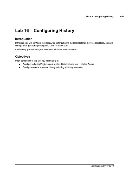
Lab 16 –Configuring HistoryIntroductionIn this lab, you will configure the Galaxy for historization to the local Historian Server. Specifically, you will configure the $gAppEngine object to store historical data.Additionally, you will configure the object attributes to be historized.ObjectivesUpon completion of this lab, you will be able to:Configure a $gAppEngine object to store historical data to a Historian ServerConfigure objects to enable history including a History extensionConfigure Objects for HistoryIn the following steps, you will configure multiple objects in the Galaxy to begin historizing data.1.In the Deployment view, double-click AOSPlatform1to open the configuration editor.2.On the General tab, in the History store forward directory field, enter C:\S&F.3.Save and close the configuration editor.4.In the Check In dialog box, Comment field, enter Store and Forward configuration and click OK.5.Double-click AppEngine1to open the configuration editor.6.On the General tab, check the Enable storage to historian check box.7.In the Historian field, enter [your instructor will confirm the computer name]. In this image,TrainingPC-ENG2will be used.8.Save and close the configuration editor.9.In the Check In dialog box,Comment field, enter Historian configuration and click OK.10.In the Template Toolbox,Working toolset, double-click $Mixer to open the configuration editor.11.In the Inherited field attributes list, select LT.PV and check the Enable history check box.12.In the Trend high field, enter 100.0and lock the history group.13.Save and close the configuration editor.14.In the Check In dialog box,Comment field, enter LT historization and click OK.15.When the Check In progress shows Object 1 of 1 completed, click Close.16.In the Template Toolbox,Working toolset, double-click Inlet1to open the configuration editor.17.Check the Historize PV check box and lock the PV group.18.Save and close the configuration editor.19.In the Check In dialog box,Comment field, enter PV historization and click OK.20.When the Check In progress shows Object 1 of 1 completed, click Close.21.In the Template Toolbox,Working toolset, double-click Agitator to open the configuration editor.22.On the Extensions tab, Extendable Attributes list, select Speed.23.Configure the Speed attribute as follows:History extension checked and lockedEngineering units:RPMTrend high:50Description:Agitator Speed24.Save and close the configuration editor.25.In the Check In dialog box,Comment field, enter Speed historization and click OK.26.When the Check In progress shows Object 1 of 1 completed, click Close.The Deployment view now displays several objects that need to be redeployed.27.Deploy AOSPlatform1and keep the default options.28.When the Deploy progress displays 100% completed, click Close.View the Historical Data with Historian ClientNow, you will use Wonderware Historian Client Trend to view a trend of the historical data.29.Start Wonderware Historian Client Trend (Start | All Programs | Wonderware | Historian Client |Trend).The Server List Configuration dialog box appears.30.In the Server field, enter [check with your instructor]. In this image, TrainingPC-ENG2will be used.31.Check the Use Integrated security check box and click Add.After a few moments, the computer name appears in the Server list.32.Click Close.The Wonderware Historian Client Trend window opens and in the Tag Picker pane, all of the tags configured for historization are displayed.33.Double-click the Agitator_001.Speed tag to add it to the trend chart.The Agitator_001.Speed historical data now displays in the trend chart.You can also drag and drop tags to the trend chart to add them.34.Drag and drop Inlet1_001.PV and M1XX.LT.PV onto the trend chart.Your trend chart will now display all three tags at the same time.35.On the toolbar, click the Enable or disable live or replay mode button.The trend chart now updates automatically.36.Close the Trend application.The Wonderware Historian Client dialog box appears.37.Click No .。
wonderware ide 培训的手册文档第11章
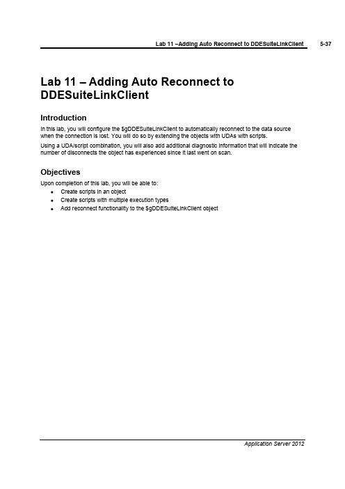
Lab 11 –Adding Auto Reconnect to DDESuiteLinkClientIntroductionIn this lab, you will configure the $gDDESuiteLinkClient to automatically reconnect to the data source when the connection is lost. You will do so by extending the objects with UDAs with scripts.Using a UDA/script combination, you will also add additional diagnostic information that will indicate the number of disconnects the object has experienced since it last went on scan.ObjectivesUpon completion of this lab, you will be able to:Create scripts in an objectCreate scripts with multiple execution typesAdd reconnect functionality to the $gDDESuiteLinkClient objectAdd the Auto Reconnect FunctionalityIn the following steps, you will create a script that will automatically reconnect to the data source when the connection is lost.1.In the Template Toolbox,Global toolset, double-click $gDDESuiteLinkClient to open theconfiguration editor.2.On the Scripts tab, click the Add Script button. the new script Reconnect and press Enter.4.Configure the Reconnect script as follows:Aliases:lockedDeclarations:lockedScripts: Execution type:Execute(default) and lockedBasics lockedExpression: Me.Connectionstatus<>2Trigger Period:00:00:05.0000000Script body Me.Reconnect=true;This script will attempt to reconnect every 5 seconds when not connected to the data source.Now, you will validate the script syntax by using the Validate feature. If the script has a syntax error, it will appear in the yellow bar just above the script body area.5.To the right of the Execution type drop-down list, click the Validate button.6.In the UDAs tab, click the Add button.7.Rename the new UDA t and press Enter.8.Configure the t UDA as follows:Data type:IntegerCategory:Calculated9.In the Scripts tab, click the Add button. the new script Disconnect.Monitor and press Enter.11.Configure the Disconnect.Monitor script as follows:Aliases:lockedDeclarations:lockedScripts: Execution type:Execute(default) and lockedBasics lockedExpression: Me.Connectionstatus<>2Trigger type:OnTrueScript body t=t+1;This script will increase a counter by one every time the condition is true.12.Click the Validate button.You will now add code within the same script under a different execution type that will run when the object goes on scan.13.While still in the Disconnect.Monitor script, change the Execution type to OnScan.14.In the script body, type t=0;.This script will reset the counter to zero every time the object goes on scan.15.Save and close the configuration editor.16.In the Comment field of the Check In dialog box, type Reconnect script and click OK.17.When the Check In progress displays Object 1 or 1 completed, click Close.18.Redeploy PLCSim, leaving the default options.19.When the Deploy progress displays 100% completed, click Close.View the Scripts in RuntimeNext, you will use Object Viewer to view the runtime data of the scripts.20.In the Deployment view, right-click PLCSim and select View in Object Viewer.21.Click on the PLCSim tab.Add the following attributes to the watch window:tDisconnect.Monitor.ExecutionCntReconnect.ExecutionCnt22.Save the watch window.Note:Your instructor will now disconnect your connection to the Device Integration server, and then reconnect the connection so that you can observe the behavior.Your Watch List now displays that there was a disconnect, but the connection has been restored.。
wonderware ide 培训的手册文档第20章,共21章
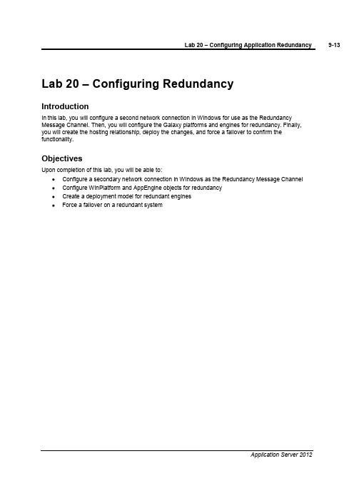
Lab 20 –Configuring RedundancyIntroductionIn this lab, you will configure a second network connection in Windows for use as the Redundancy Message Channel. Then, you will configure the Galaxy platforms and engines for redundancy. Finally, you will create the hosting relationship, deploy the changes, and force a failover to confirm the functionality.ObjectivesUpon completion of this lab, you will be able to:Configure a secondary network connection in Windows as the Redundancy Message Channel Configure WinPlatform and AppEngine objects for redundancyCreate a deployment model for redundant enginesForce a failover on a redundant systemConfigure Windows for RedundancyIn the following steps, you will configure a second network connection in Windows as the Redundancy Message Channel (RMC). This will need to be done on both computers, where the first is the computer where GRPlatform is deployed and the second is the computer where AOSPlatform1is deployed.1.Connect to the machine where the GRPlatform is installed [for the remote computer, this will be themachine where the AOSPlatform1in installed].2.Open Network Connections(Start | Control Panel | Network and Sharing Center).3.Click Change adapter settings.The Network Connections window appears.4.Right-click Local Area Connection and select Rename.5.Rename the connection ArchestrA.6.Right-click Local Area Connection 2and select Rename.7.Rename the connection RMC.8.Press Alt+N to unhide the Menu bar.9.On the Advanced menu, select Advanced Settings.The Advanced Settings dialog box appears.10.In the Connections area, select ArchestrA and click the Up Arrow button.The ArchestrA connection is now listed first.11.Click OK.12.In the Network Connections window, right-click RMC and select Properties.The RMC Properties dialog box appears.13.In the This connection uses the following items area, select Internet Protocol Version 4(TCP/IPv4).14.Click the Properties button.The Internet Protocol Version 4 (TCP/IPv4) Properties dialog box appears.15.Click the Use the following IP address option.16.In the IP address field, enter 192.168.1.1. [For the remote computer, this will be 192.168.1.2]17.Click in the Subnet mask field to automatically assign the subnet mask.18.In the bottom-right of the window, click the Advanced button.The Advanced TCP/IP Settings dialog box appears.19.On the DNS tab, uncheck the Register this connection’s addresses in DNS check box.20.Click OK.21.In the Internet Protocol Version 4 (TCP/IPv4) Properties dialog box, click OK.22.In the RMC Properties dialog box, click Close.23.Repeat Steps 1to 22on the remote computer where AOSPlatform1is deployed. The IP address thatwill be used on the remote computer will be 192.168.1.2.Configure the Platforms for RedundancyYou will now return to the ArchestrA IDE and configure the platforms for redundancy.24.In the Deployment view, open the GRPlatform configuration editor.25.In the Redundancy area, Redundancy message channel IP address field, enter 192.168.1.1.26.Save and close the configuration editor.27.In the Check In dialog box,Comment field, enter Redundancy configuration and click OK.28.Open the AOSPlatform1configuration editor.29.In the Redundancy group, Redundancy message channel IP address field, enter 192.168.1.2.30.Save and close the configuration editor.31.In the Check In dialog box,Comment field, enter Redundancy configuration and click OK.The Deployment view now displays that both platforms have pending changes.You will redeploy the platforms later in this lab.Configure AppEngine1 for RedundancyYou will now configure AppEngine1for redundancy. Since AppEngine1is currently deployed, you must first undeploy it.32.Right-click AppEngine1and select Undeploy.33.In the Undeploy dialog box, keep the default options and click OK.34.When the Undeploy progress is complete, click Close.35.Open the AppEngine1 configuration editor.36.On the Redundancy tab, check the Enable Redundancy check box.The Redundancy configuration settings auto populate with the default values.37.Keep the defaults and click Save and close.38.In the Check In dialog box,Comment field, enter Redundancy configuration and click OK.The Deployment view now displays the AppEngine1icon with the primary redundant engine icon.39.Expand the Unassigned Host folder to reveal the new backup application engine instance.This was automatically created when redundancy was enabled in AppEngine1.You will now have GRPlatform host the new AppEngine1 (Backup) object.40.Drag and drop AppEngine1 (Backup)onto GRPlatform.Now, you will redeploy the platforms.41.Select both the AOSPlatform1and the GRPlatform.42.Right-click either platform and select Deploy.43.Keep the default options and click OK.44.When the Deploy progress is complete, click Close.45.Return to Object Viewer.Because the platforms redeployed, you will get the following error in Object Viewer.46.Click OK.Object Viewer closes.You will now deploy the application engines using the Include Redundant Partner option.47.In the Deployment view, right-click AppEngine1and select Deploy.48.In the Deploy dialog box, check the Include Redundant Partner check box.49.Click OK.50.When the Deploy progress is complete, click Close.The Deployment view now displays that all objects have been deployed.View the Redundancy Functionality and Data in RuntimeYou will now use Object Viewer and observe selected AppEngine1attributes in the runtime environment. You will then force a failover and observe the changes.51.In the Deployment view, right-click AppEngine1and select View in Object Viewer.52.On the File menu, select Load Watch List.53.Navigate to C:\Training and select MyWatchWindow.54.Click Open.55.Add the following attributes to the watch window:HostRedundancy.IdentityRedundancy.StatusRedundancy.PartnerPlatformRedundancy.PartnerStatusRedundancy.FailoverOccurredRedundancy.ForceFailoverCmdThe watch window displays that AOSPlatform1is currently hosting AppEngine1and the redundancy status is active. Additionally, the GRPlatform is the partner platform and is currently in a Standby mode.56.Save the watch window.You will now force a failover to trigger redundancy and observe the changes.57.In the watch window, double-click AppEngine1.Redundancy.ForceFailoverCmd.The Modify Boolean Value dialog box appears.58.Click the True option and click OK.After a few seconds, the watch window displays GRPlatform as the host platform andAOSPlatform1as the partner platform.You will now refresh Object Viewer to view the changes.59.In the console tree pane, collapse and expand AOSPlatform1and GRPlatform.The pane now displays that AOSPlatform1is no longer hosting any objects and GRPlatform is now hosting all of the objects.60.Click the Mixer1tab.The watch window displays that all attributes are still running and producing good quality data.Lab 20–Configuring Application Redundancy 9-33Application Server 201261.On the Mixer2watch window, observe the same behavior.You will now force another failover to return to the primary redundancy configuration.62.In the Redundancy watch window, double-click AppEngine1.Redundancy.ForceFailoverCmd .63.In the Modify Boolean Value dialog box, click the True option and click OK .After a few seconds, the watch window displays AOSPlatform1as the host platform andGRPlatform as the partner platform.You can also observe what happens when the connection to the remote computer loses connectivity.64.Disable the RMC network connection.After a few seconds, the watch window now displays that the Standby Status isActive –Standbynot Available.9-34Module 9–RedundancyInvensys Learning Services 65.Reenable the RMC connection.After a few seconds, the watch window displays the Standby Statusis back to Active .。
wonderware ide 培训的手册文档第9章
Lab 9 –Creating the MixerIntroductionIn this lab, you will use the valve and motor templates that you created in previous lab to create dedicated templates for each mixer component. You will use these templates and the mixer template to create an object containment, which integrates all of the parts that make up the mixer.You will then update the existing instance by adding instances and configure their attribute references so that their values can be viewed in Object Viewer.Finally, you will create a new instance of the mixer container, which will also create all of the instances of the container and the contained objects.ObjectivesUpon completion of this lab, you will be able to:Create contained templates and a containment relationshipUpdate an existing mixer instanceDeploy contained instancesCreate a new containment instanceCreate the Mixer Containment RelationshipIn the following steps, you will create templates for the parts of the mixer container.1.In the Template Toolbox,Working toolset, right-click $Valve and select New | Derived Template.2.Rename the template $Inlet1.3.Right-click $Valve and select New | Derived Template.4.Rename the template $Inlet2.5.Right-click $Valve and select New | Derived Template.6.Rename the template $Outlet.7.Right-click $Motor and select New | Derived Template.8.Rename the template $Agitator.You will now assign the newly created templates to the mixer template to create a container at the template level.9.Drag and drop the following templates onto the $Mixer template:$Inlet1$Inlet2$Outlet$AgitatorContained templates lose the $at the beginning of their names. If you were to take one or more out of the containment relationship, the $would reappear.Now, you will create instances for all the contained objects that will be added to the existing Mixer_001.10.Display the Model view.11.In the Template Toolbox,Working toolset, right-click Agitator and select New | Instance. Keep thedefault name.12.Create the following instances and keep the default names:The Model view now displays the new instances in the Unassigned Area folder.Configure the Existing Mixer InstanceYou will now create the containment at the instance level.13.In the Model view, assign all four instances in the Unassigned Area folder to the Mixer_001instance.The four contained object instances display configuration warnings, which you will resolve later in this lab.The contained name displays next to an object name in brackets. You will now change the contained name for the new four instances to match the template names.14.In the Model view, right-click Agitator_001and select Rename Contained Name.The Rename Contained Name dialog box appears.15.Rename the contained name Agitator and click OK.The Model view now displays the new contained name for the Agitator_001object.16.Rename the contained names for the following:Inlet1_001change to Inlet1Inlet2_001change to Inlet2Outlet_001change to OutletConfigure I/O for Valves and AgitatorNext, you will configure the attribute references for the newly created contained instances.17.In the Model view, open the Agitator_001configuration editor.18.On the Inputs tab, click the ellipsis button next to the Input Source Reference field.The Galaxy Browser -TrainingGalaxy window appears.19.In the Instances pane, click PLCSim.20.Select the Tagname.M1XX_AG_AuxContact attribute, where XX is your student number. In thisimage, 00will be used.21.Click OK.The Input Source Reference field is now populated with the correct attribute reference.22.In the Outputs tab, click the ellipsis button next to the Output Destination Reference field.23.Select the Tagname.M1XX_AG_CmdStart attribute and click OK.The Output Destination Reference field is now populated with the correct attribute reference.24.Save and close the configuration editor.25.In the Check In dialog box,Comment field,enter I/O references configuration and click OK.26.Open the Inlet1_001configuration editor.27.In the Inputs tab, configure the Input Source Reference as follows:Input 2: CLS Tagname.M1XX_IV1_CLSInput 1: OLS Tagname.M1XX_IV1_OLSThe Input Source Reference fields now display the correct attribute references.28.In the Outputs tab, configure the Output Destination Reference as follows:Output 1: CmdOpen Tagname.M1XX_IV1_CmdOpenThe Output Destination Reference field now displays the correct attribute reference.29.Save and close the configuration editor.30.In the Check In dialog box,Comment field,enter I/O references configuration and click OK.31.Open the Inlet2_001configuration editor.32.In the Inputs tab, configure the Input Source Reference as follows:Input 2: CLS Tagname.M1XX_IV2_CLSInput 1: OLS Tagname.M1XX_IV2_OLSThe Input Source Reference fields now display the correct attribute references.33.In the Outputs tab, configure the Output Destination Reference as follows:Output 1: CmdOpen Tagname.M1XX_IV2_CmdOpenThe Output Destination Reference field now displays the correct attribute reference.34.Save and close the configuration editor.35.In the Check In dialog box,Comment field,enter I/O references configuration and click OK.36.Open the Outlet_001configuration editor.37.In the Inputs tab, configure the Input Source Reference as follows:Input 2: CLS Tagname.M1XX_OV_CLSInput 1: OLS Tagname.M1XX_OV_OLSThe Input Source Reference fields now display the correct attribute references.38.In the Outputs tab, configure the Output Destination Reference as follows:Output 1: CmdOpen Tagname.M1XX_OV_CmdOpenThe Output Destination Reference field now displays the correct attribute reference.39.Save and close the configuration editor.40.In the Check In dialog box,Comment field,enter I/O references configuration and click OK.The Model view no longer displays any exclamation points.Deploy the InstancesEven though Mixer_001is already deployed, the newly contained instances still need to be deployed.41.In the Deployment view, select all four new instances.42.Right-click on any of the highlighted instances and select Deploy.43.Keep the default options and click OK.44.When the Deploy progress displays 100% completed, click Close.View the Mixer Data in RuntimeYou will now return to Object Viewer to observe the attribute values in runtime.45.Right-click on Mixer_001and select View in Object Viewer.Object Viewer appears and is refreshed.Although the container relationship was created and the container deployed, Object Viewer does not display this relationship in the object list.46.In the details pane, add the following attributes to the watch window:The data being displayed is updating in the watch window.47.Save the watch window.Create a New Instance of $MixerNext, you will create a new instance of the mixer template.48.In the ArchestrA IDE,Template Toolbox,Working toolset, right-click $Mixer and select New |Instance.49.In the Model view, under the Unassigned Area folder, expand the Mixer_002instance.Mixer_002has the contained instances of the mixer created with the correct contained names, as well as the mixer instance.The configuration warnings and deployment for these objects will be addressed in a later lab.。
- 1、下载文档前请自行甄别文档内容的完整性,平台不提供额外的编辑、内容补充、找答案等附加服务。
- 2、"仅部分预览"的文档,不可在线预览部分如存在完整性等问题,可反馈申请退款(可完整预览的文档不适用该条件!)。
- 3、如文档侵犯您的权益,请联系客服反馈,我们会尽快为您处理(人工客服工作时间:9:00-18:30)。
Lab 2 – Identifying the Mixer
Course Description and Objectives
Course Description
The System Platform – Part 1 training course is a 4-day instructor-led course designed to give the knowledge necessary to develop and support applications with Wonderware Application Server.
System Platform
Clients
Microsoft Technologies & Industry Standards
Wonderware System Platform
InTouch
(Visualization)
Wonderware Clients
ActiveFactory
(Analysis Client)
?Leverage the .NET Framework for the Automation World
?Object-based application
?One global networked namespace
?Centralized configuration and security
?Multi-user development environment ?Component-based plant application model ?Self documenting
Application Server Galaxy
Galaxy Repository
Single computer and software where the Galaxy database is located.
Wonderware Application Server
+++ Scan-based system. Highlights
Sources
Software Applicatio
ns
3rd Party Controllers
Concepts and Terminology
It is an open and extensible system of components based on a distributed, objectoriented design.
Information Server CAL
(Report Client)
Wonderware System Platform
Application Server
Historia n
Information Server
Device Integration Products
3rd Party Data
System Platform
Module 1: Introduction
Contents
Section 1: Course Introduction Section 2: Wonderware System Platform
Lab 1 – Creating a Galaxy Section ቤተ መጻሕፍቲ ባይዱ: The ArchestrA IDE Section 4: Automation Objects Section 5: System Requirements, Licensing and
? Be able to troubleshoot applications in a standalone and networked environment.
Wonderware System Platform
Project Specific Work
Industry Packs
Function Specific Modules
Course Objectives
? Understand the ArchestrA? technology and how it is applicable to the plant floor environment.
? Become familiar with developing objects and instances configuring applications using the Integrated Developing Environment.
System Platform
Clients
Microsoft Technologies & Industry Standards
Wonderware System Platform
Project Specific Work
Industry Packs
Function Specific Modules
ArchestrA
It provides a unified environment for visualization, plant history, device communications and automation application integration.
Application Server's application, configuration information and project database.
System Platform 3.1
Wonderware? System Platform 3.1
System Platform
Agenda
Contents
Module 1: Introduction Module 2: Application Infrastructure Module 3: Application Objects Module 4: Extending the Objects Module 5: Alarms and History Module 6: Security Module 7: Galaxy Maintenance Module 8: Device Integration Products Module 9: Multi-Node Applications