电子指南针使用手册
睿石企业级APM指南针产品快速配置手册说明书

睿石企业级APM指南针产品快速配置手册睿石网云(北京)科技有限公司2017年07月04日声明本手册所含内容若有任何改动,恕不另行通知。
在法律法规的最大允许范围内,睿石网云(北京)科技有限公司除就本手册和产品应负的瑕疵担保责任外,无论明示或默示,不作其它任何担保,。
在法律法规的最大允许范围内,睿石网云(北京)科技有限公司对于您的使用或不能使用本产品而发生的任何损坏(包括,但不限于直接或间接的个人损害、商业利润的损失、业务中断、商业信息的遗失或任何其它损失),不负任何赔偿责任。
本手册含受版权保护的信息,未经睿石网云(北京)科技有限公司书面允许不得对本手册的任何部分进行影印、复制或翻译。
睿石网云(北京)科技有限公司章节目录目录声明 (2)1. 前言 (4)1.1. 导言 (4)1.2. 本书适用对象 (4)1.3. 本书适合的产品 (4)2. 如何开始 (4)2.1. 准备工作 (4)2.2. 配置管理方法 (4)3. 网络环境 (5)3.1. 网络拓扑 (5)3.2. 拓扑描述 (5)4. 部署步骤 (6)4.1. 配置交换机端口镜像或Flow (6)4.2. 采集配置 (6)4.3. 业务对象定义 (7)4.3.1. 主机组配置 (7)4.3.2. 自定义业务配置 (7)4.4. 配置下发 (8)4.5. 业务视图配置 (8)4.6. 完成配置 (9)5. 附录 (9)5.1. 华为交换机端口镜像配置示例 (9)5.2. Cisco路由器netflow V5开启flow配置示例 (10)5.3. 华为netstream版本5开启flow配置示例 (10)5.4. H3C开启flow配置示例 (10)6. 关于RStone睿石 (11)1.前言1.1.导言《睿石企业级APM---指南针产品快速配置手册》是睿石APM产品主要的安装调试手册。
产品简称:指南针或者Compass系统,下文中将直接引用该名称。
电子指南针说明书

摘要早期的指南针采用了磁化指针和方位盘的组合方式,整个指南针从便携性、指示灵敏度上都有一定不足,极易受到外界因素的干扰。
本系统采用专用的磁场传感器结合高速微控制器〔MCU〕的电子指南针能有效解决这些问题。
系统采用了磁阻〔GMR〕传感器采集某一方向磁场强度后通过MCU控制器对其进行处理并显示上传,通过对电子指南针硬件电路和软件程序的分析,阐述了电子指南针基本的工作原理及实现。
实际测试指南针模块精度达到1°,能够在LCD上显示当前方位并能通过键盘控制实现磁场校准,磁偏角补偿,重新设定等功能。
关键词:电子指南针;磁阻传感器;单片机;液晶AbstractSince the early use of amagnetic compass and direction-pointer of the composition, the entire compass from scratch, on the instructions of a certain sensitivity of the defect. Using a dedicated high-speed magnetic sensors with microcontroller <MCU> electronic compass can effectively solve these problems. The system is designed by the reluctance <GMR> sensors collecting a certain direction through the magnetic field strength after the MCU Controller its judgement will be dealt with the results, through the LCD screen display and can be sent to the MCU's top serial Machine. The actual test compass module can reach 1 °, in the LCD display on the current position and through the keyboard control can realize functions like the magnetic field calibration,Magnetic declination, Reset etc.Key words: electronic compass; GMR; MCU; LCD目录摘要I1 引言11.1 课题背景11.2 指南针原理介绍11.3 国外研究现状21.4 本课题研究的意义22 单片机及相关物理量介绍42.1 单片机系统简介42.2 物理量简介72.3 电子指南针的主要偏差及校正93 原理及系统框图133.1 测量原理简介133.2 系统总图框图143.3 系统其他模块简介154 系统硬件244.1 系统控制模块244.2 指南针模块254.3 实时时钟模块264.4 液晶显示电路274.5 系统输入电路285 系统软件305.1 主监控程序305.2 实时时钟驱动315.3 指南针模块驱动325.4 键盘驱动345.5 液晶模块驱动34结论36致37参考文献36附录371 引言1.1 课题背景指南针的发明是我国劳动人民,在长期的实践中对物体磁性认识的结果。
指南针使用手册
指南针使用手册一、使用注意事项指南针务必水平地拿着,而且要远离以下列举的各种物品,才可避免磁针发生错乱:指南针应离铁丝网10米,高压线55米,汽车和飞机20米,以及含有磁铁如磁性容器等10米。
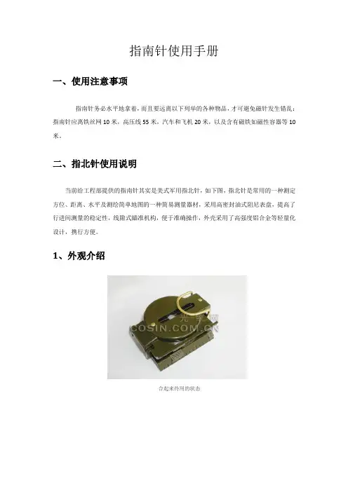
二、指北针使用说明当前给工程部提供的指南针其实是美式军用指北针,如下图,指北针是常用的一种测定方位、距离、水平及测绘简单地图的一种简易测量器材,采用高密封油式阻尼表盘,提高了行进间测量的稳定性,线隙式瞄准机构,便于准确操作,外壳采用了高强度铝合金等轻量化设计,携行方便。
1、外观介绍合起来待用的状态打开后的状态完全打开放平后带刻度的边缘部分,是1:25000M的坐标梯尺,可以在相同比例的地图上直接量测直线距离,同时是几何方法图上作业的得力工具,如下图:阻尼表盘有利于指针的稳定性,更加适合运动、崎岖的环境,箭头表示N极(北极),这也是绝大多数指北针的标注方法:可以转动的方位表牌,通过一个片状卡簧和表牌的齿状边缘卡紧和定位方位表牌上有一个放大镜,可以更清楚地看到方位,不要小看这一长一短两条刻线,很多功能都要通过它实现:阻尼表盘内圈的刻度为360度方位角度分划,外圈的刻度为64-00密位制分划,密位分划是军事上常用的方位角计量单位,美国和原北约国家的标准是64-00制,我国和原华约国家的标准是60-00制,根据不同的密位制相应的1密位换算为角度=360/密位制(度),美式64-00密位制指北针1密位=360/6400=0.05625(度),我国的97型指北针采用的为60-00密位制,1密位=360/6000=0.06(度)。
2、使用方法(1)确定北方:正确的方法是这样的,在手掌中端平,箭头(N极)所指的就是北方:(2)校正地图:校正地图的方向很简单,但这是一切图上作业的基础:把地图放平,然后将地图上的指北标与指北针上的N极(箭头)对正,就校正了地图方向,一般情况下地图都是上北下南绘制的。
(3)测量方位:利用这个小透镜和表壳上的金属丝配合使用,可以更精确的测量方位角,透镜上方的小缝可以使你更准确地定位金属丝,具体的方法是从小透镜通过指北针狭缝中的细金属丝瞄准目标,然后转动方位表牌使长线对准卡簧尖,然后从方位表牌的透镜中读角度,即方位线与正北的夹角角度。
说明书电子指南针
数字罗盘说明书1. Introduction 介绍1.1 功能* 高度计* 数字罗盘* 大气压强(hPa, inHg, mmHg)* 温度 (℃ or ℉)* 256 组历史记录(海拔和大气压强数据)* 天气预报图标的变换(基于大气压强的变化)* 12/24 小时的始终格式* 万年历* 手调时间和日期* LED背光* 织带包含,便于携带1.2 按键功能如果按键不被按动30分钟,(气压变化在0.4Hpa), LCD 屏幕显示关闭。
按任何键,则恢复到正常显示。
1.2.1 按键“ALTITUDE/+”- 当处于设置模式,按下“ALTITUDE/+”按键,则可以增加值。
- 当处于正常显示模式下,按下“ALTITUDE/+”按键,则可以在大气压强和高度(相对/绝对)之间切换。
- 当处于海拔高度(绝对)显示时,按下“ALTITUDE/+”按键并保持不动2秒,海拔高度(绝对)将会被重置到相对高度,起始值为0 。
当处于相对高度显示时,按下“ALTITUDE/+”按键并保持不动2秒,相对高度将会被重置到海拔高度(绝对)。
备注:当累计高度的显示有需要的情况下,相对高度是很有用的。
1.2.2 按键“COMPASS/-”- 当处于设置模式,按下“COMPASS/-”按键,则可以减少值。
- 当处于正常显示模式下,按下“COMPASS/-”按键,则可以进入罗盘模式- 当处于罗盘模式下,按下“COMPASS/-”按键,则可以切换显示数字模式和指针模式。
- 按下“COMPASS/-”按键并保持不动2秒,则进入校正模式。
1.2.3 按键“SET”- 当处于正常显示模式下,按下“SET”按键,可以切换到时间和日期。
-当处于正常显示模式下,按下“SET”按键并保持不动6秒,则进入节能模式:LCD 关闭,但是,时钟还在工作。
此时,按下任何按键,将返回到正常的LCD 显示模式。
-当处于正常显示模式下,按下“SET”按键并保持不动2秒,则进入设置模式。
Silva Ranger系列指南针说明书

A PRECISION INSTRUMENT DESIGNED FOR PROFESSIONAL USE.INSTRUCTION MANUALRANGER COMPASS model: 515Y our Silva Ranger series compass is a precision instrument made by experienced special-ists in this field; it is the finest hand compass available for professional use. Y our Silva Ranger is finely crafted to withstand rigors associated with the outdoor professions. It is a rugged, durable piece of equipment that, with proper care, will remain dependable and accurate.W e recommend that you read this manual to understand the basic functions of the com-pass. When you read, keep in mind that no two compass applications are identical.The instructions given here are intended to provide you with a working knowledge that you will be able to apply in almost any situation.T he illustrated 360 Degree Graduations are based on standard dial graduations of 360 degrees, in 2º increments. With this graduation North is 0º and increases clockwise so East is 90º, South is 180º, West is 270º and 360º is again North. 0º and 360º are the same direction.T he Silva Ranger Model 515CLQ has Quadrant Graduations. With this graduation North is 0º and increases clockwise so East is 90º then it decreases so South is 0º then increases so West is 90º and then decreases so North is 0º. Instructions inthis manual will apply to this graduation except when it is necessary to refer to the proper “quadrant,” such as North 20º East, or North 15º West, or South 40º East or South l0º West.compass coverluminous pointsbase plateblack clinometerpointermagnetic needle withred north2X magnifierscale in mm sightmirrorsighting lineindex pointer orienting arrow with red north endmeridian linesliquid filled capsulebezel with2º graduationsscale in inchesGENERaL SuGGESTIoNSY our Silva Ranger compass may be used for finding directions with or without the aid of the sighting mirror. LEaRN BoTH Wa YS.1. When extreme accuracy required: With the sighting mirror, hold compass ateye level with cover opened to an acute angle.2. When quick accuracy required: With the sighting line as a direction pointer,hold the compass at waist level with cover wide open. In either instance, thecompass must be held level enough to permit the needle to swing freely.B e aware of nearby iron or steel objects. They may attract the magnetic needle if veryclose to compass. Even a hidden nail can deflect the needle if too close.a small bubble may form in the liquid compass, but it has no influence on accuracy. Theappearance and disappearance of this bubble is due to changes in temperature and atmospheric pressure. Bubbles larger than 1/4" diameter, however, should be viewed with suspicion and probably are caused by a leaking capsule.T o increase their brilliance,expose the luminous points to bright light before use.P rotect your compass from high temperatures extremes. The heat expanded liquid could damage the capsule.THE CLINoMETERT he SILVa Ranger compasses are practical instruments for measuring angles of inclina-tion. The long side of the compass coincides with the slope of the terrain. Measure an angle of inclination in the following way:1 open the lid completely.2.T urn the dial so that the cardinal point “W” on the dial is set at the index pointer.3. Hold he compass at eye level with arms out-stretched so that the clinometer needleis hanging vertically and follows the scale in the bottom of the compass housing. “S”on the compass should point down.4. Let one long side of the compass coincide with the slope of the terrain— the incli-nation you wish to measure.5. Read the angle of inclination at the point of the clinometer needle.RuLES of uSET wo separate sets of rules apply to the use of a magnetic compass. one set applies if you work “from map to terrain.” In this case you take “map bearings.” In the following,Sections a, B, C, D and E deal with “from map to terrain.”E xactly opposite rules apply if you work “from terrain to map.” In this case you use “fieldbearings,” also called “magnetic bearings” and “compass bearings,” Sections f, G and H deal with “from terrain to map.”T he word “map” is broadly interpreted to also include charts, descriptions and even a mental picture of the terrain.BaSIC CoNDITIoNS To DETERMINE fIELD DIRECTIoNS Section AT o use the compass to indicate directions in the field, two basic conditions must always be accomplished. These are:1. The dial must be set to the desired degree reading. If the degree or direction isknown, turn the dial to the correct reading at the index pointer. If the degree isunknown, then it should be obtained from a suitable map.2. Without changing the dial setting, the entire compass must be positioned so thatthe orienting arrow lines up with the magnetic needle and the red end of needle lies between the two orienting points.W hen both conditions are fulfilled, the desired direction is indicated by the sighting line or by the sight.DETERMINE DIRECTIoNS WITHouT THE SIGHTSection BT o fulfill the two conditions described in Sect. a:Set dial according to Sect. a (1) With the dial set, open the cover wide and hold it waist high in front of you. The sight and sighting line should be pointing ahead of you not back toward your body. The sighting line now acts as a pointer. T urn your-self and compass together until the orienting arrow is lined up with the magnetic needle. This accomplishes Sect. a (2) and the sighting line now will be pointing the correct direction.While still holding the compass, imagine a line extending exactly straight out from the sighting line. Y our objective lies along that imaginary line.DETERMINE DIRECTIoNS WITH a SIGHTSection CT o fulfill the two conditions described in Sect. a:Set the dial according to Sect. a (1).Hold the compass at eye level and adjust the cover to a 50º—70º opening. The mirror should reflect a top view of the compass dial.While looking in the mirror, move your sighting eye sideways until you see the sighting line intersect one of the two luminous points.Without changing the relationship between compass and eye, pivot yourself and compass together until you see, in the mirror, that the orienting arrow is lined up with themagnetic needle and the red end of needle is between the orienting points. Thisaccomplishes Sect. a (2).Y our direction or objective will now lie straight beyond the sight.NoTE: Be sure to keep the base plate level so magnetic needle can turn freely. When sight-ing uphill or downhill, lower the sighting eye in relation to the compass.NoTE: a greater than 70º cover opening will increase the parallax effect and could cause as much as a 5º reading error.oBTaIN a BEaRING fRoM a MaPSection DW e state in Sect. a, that one of the two conditions for using the Silva Ranger is to setthe dial at the desired degree reading. If this degree or bearing is not known, it can be determined from a map. Y our compass is also a protractor with a transparent bottom in the dial housing. T wo steps are required:1. Lay the compass on the map so either the inch scale or the millimeter scale isexactly on (or parallel with) the line on the map you wish to travel, and the hinged cover points in the direction of travel.2. Hold the compass in position on the map, turn the dial so the meridian lines of thecompass are exactly parallel with any meridian (North-South) line on the map, and the letter “N” on top of the dial is toward North on the map.R emove the compass from the map. These two steps set your compass for the degree reading to your destination. This reading may be read at the index pointer. Y ou fulfilled the first basic condition in Sect. a. Proceed to Sect. B or C.aBouT DECLINaTIoNSection ET he magnetic needle in a compass is attracted by the magnetism of the Earth. This is why it always points to the constantly shifting Magnetic North where the magnetic lines of force come together. There is another “North Pole.” T rue North is static and located geographically, maps and directions usually are based on T rue North.M agnetic declination is the angle between T rue North and Magnetic North. The amount of declination at any given point depends on the location of that point on the continent.Where T rue and Magnetic North are in the same direction, the declination is zero.In North america a line of zero declination runs roughly from west of Hudson Bay down along Lake Michigan to the Gulf Coast in western florida. at any point west of that line, your compass needle will point east of T rue North. This is called “Easterly Declination.” at any point east of that zero line, your compass needle will point west of T rue North. This is called “Westerly Declination.” In North america, magnetic decli-nation varies from 30º east in alaska to 30º west in Labrador. See diagram on page 9. allow for DeclinationW here accuracy is not critical, ignore magnetic declination, especially in areas where the declination is minor. Y ou may also ignore it when the compass is used without refer-ence to maps and is based on field bearings only.W hen the compass is used with a map or in connection with map bearings, adjustment should be made. There are two methods to accomplish this:1. T emporary Method. Y ou must redo every time you wish to apply it.find the amount of declination in their area and whether it is easterly or westerly. This information is on topographic maps of the area.T ake your bearing from the map as described in Sect. D. and observe the degree read-ing at the index pointer.T urn the dial to increase or decrease that reading according to the declination. Easterly, decrease the dial reading and westerly, increase the reading.for example, if your bearing from the map is l00º and the declination is 10º East,DECREaSE the reading 10º by turning the dial to 90º. If the declination is 10º West, INCREaSE the reading of l00º to read 110º.2. Permanent Method. Y our compass is equipped with an offsetting mechanism to allowfor declination. If you use the compass extensively in one locality, once set, you need not make further allowances. The adjustment simultaneously takes care of both map bearings and field bearings.The offsetting mechanism consists of two bottoms in the compass dial housing, oneof which can be offset in relation to the other by means of a declination adjustingscrew located on the underside of the base plate. The orienting lines and the declina-tion scale are engraved on one bottom. The orienting arrow and the orienting points are on the other. as you turn the adjusting screw you change the angle between the orienting lines and the orienting arrow. It is this angle that should correspond to the declination of your area. a screwdriver, provided for this purpose, is tied onto thelanyard.for example, if the declination in your area is 10º west, turn the adjusting screw sothat the orienting arrow points to 10º on the “west” side of the declination scale.If your declination is 10º east, adjust the orienting arrow to 10º on the “east” sideof the declination scale. use the black index line of the orienting arrow to make an accurate setting.NoTE: The declination offsetting mechanism is set at zero at the factory. use the zero set-ting for all compass operations which involve no allowance for declination or in which the temporary allowance is being used. If the declination scale does not read zero, set it to zero with the adjusting screw.NoTE: When the orienting arrow is not set at zero, it becomes obvious that the orienting lines and the orienting arrow serve different purposes. The orienting lines are used to line up with orienting lines on the map. The orienting arrow is used to line up with the magnetic needle when using compass in the field.TakE a BEaRINGSection Fa“bearing” is the direction or the degree reading from one object to another. one of those objects is usually You. T o “take” a bearing means to DETERMINE the direction from one object to another.1. Bearings are taken from a map as in Sect. D. The “bearing” is the degree reading indi-cated at the index pointer.2. Bearings can be taken on the terrain, by reversing the steps in Sect. B and C. Whenusing the compass without the sight, open the cover wide and hold it level, at waist high, in front of you. The sight and sighting line should be pointing straight ahead of you. The sighting line acts as a pointer. Pivot yourself and compass together untilthe sighting line points straight to the object on which you are taking the bearing.Without changing position of the compass, carefully turn the dial until the orienting arrow and the magnetic needle are lined up and with the red end of needle lyingbetween the two orienting points. The “bearing” to your object is now the degree reading indicated at the index pointer.3. Bearings can be taken by using the sight. Hold the compass at eye level and adjustcover so top of the dial is seen in mirror. face toward your object and sight object across compass sight. Look in the mirror and adjust position of compass so thatthe sighting line intersects one of the luminous points. While you simultaneouslysee your object across the sight, and the sighting line across one of the luminouspoints, turn the dial so that the orienting arrow is lined up with the needle, red end between the orienting points. The “bearing” to your object is now the degree read-ing indicated at the index pointer.aDjuST fIELD BEaRINGS foR DECLINaTIoNSection G1.The permanent adjustment for declination eliminates need for further adjustment.2. T o accomplish the temporary adjustment for field bearing declination: T ake a bearingas described in Sect. f and observe the degree reading at the index pointer. T urn the dial to increase or decrease that reading according to the declination. If declination of your area is easterly, increase your dial reading by the amount of declination. Ifwesterly, decrease the reading.for example, assume your field bearing is 100º. If the declination is 10º east, INCREaSE the reading 10º by turning the dial to read 110º. If the declination is 10º west,DECREaSE the reading of 100º to read 90º.NoTE: The instructions for a “temporary” adjustment for declination of a field bearing are exactly opposite from the temporary adjustment of a map bearing.NoTE:The declination scale should be set at zero for all compass operations which involve noA “Short-Cut” Method to Deal with Declination:W hen the compass is used with a map, no adjustment is necessary if the orienting lines on the map are drawn according to Magnetic North instead of T rue North. Mosttopographic maps are drawn according to T rue North and the orienting lines are also according to T rue North.D raw your own orienting line according to Magnetic North:on all topographic maps, there is a declination diagram near the bottom. The star line designates T rue North and is parallel with the orienting lines. However, the single barb arrow designates Magnetic North. Draw your own Magnetic North orienting lines by drawing 1" or 2" lines across the map that are parallel to the Magnetic North arrow.use these lines instead of the T rue North lines when setting your compass and you will not need to adjust for declination.PLoT LoCaTIoNS oN a MaPSection IT riangulation method:find two specific sites (a) and (b) on the map which you recognize, by sight, on the terrain. These are the chosen points from which to take cross bearings.adjust your compass for the declination of your area by the permanent method.T ake a bearing to the first site (a)— without disturbing the dial setting.Place the compass on the map so that either side of the base plate intersects thesymbol for the chosen site (a). keep the edge of compass base plate on the symboland turn entire compass on the map until the compass orienting lines in the bottom of the dial are parallel with the orienting lines on the map, and so that the orienting arrow points upward on the map (North).NoTE: orienting arrow may be slightly off of North because of declination adjustment.Draw a line on the map along the edge of the compass, intersecting the symbol. Y ou are somewhere along this line. T o establish your position along this line, you needanother bearing.T ake a bearing to the second site (b) and mark a line as you did with site (a). This line will intersect the first line. Where the lines cross is your exact position.BE EXPERT WITH MaP aND CoMPaSS, Second EditionBjörn kjellströmT his new and enlarged edition includes everything you need to know about the skill of orienteering; how to use a map and compass, alone or together. The text includes a series of games and exercises which encourage self-training. Each copy of the book also contains a sample training map to help you put newfound knowledge into practice.Required reading for the beginner in map and compass work.Johnson Outdoors Inc. © 2007 p/n 5793150C 2-07Johnson Outdoors Inc.625 Conklin Road Binghamton, NY 13903 Johnson Outdoors Inc. Canada 4180 Harvester Road Burlington, ontario Canada L7L 6B6 1.905.634.0023 fax 1.800.661.1170。
指南针使用说明

指南针使用说明录目1指南针的原理和历史1. ............................................................................................................................1.1.1指南针的原理...................................................................................................................................1.2.1指南针的历史...................................................................................................................................2指南针的类型2. ........................................................................................................................................4 ........................................................................................................................................ 3.指南针的结构43.1. ................................................................................................................... 军用指南针的基本结构53.2. ............................................................................................................................................... 荧光点6 ............................................................................................................................................... 3.3.反光镜6........................................................................................................... DQY-13.4.型指南针的基本结构7指南针的主要功能和使用方法............................................................................................................ 4.7测定方位........................................................................................................................................... 4.1.84.2.测量距离...........................................................................................................................................9行军时间及速度计算4.3. ............................................................................................................................................................................................................................ 104.4.. 测定斜面的坡度(俯仰角度)......................................................................................................................... 114.5.测量目标概略高度............................................................................................................. 11 4.6.DQY-1型指南针主要功能.................................................................................. 125.应用:天线方位角的定位方法和下倾角测量............................................................................................. 12规划选点中确定扇区天线的方位角5.1................................................................................................... 12 .优化中测量已安装天线的方位角5.2.................................................................................................................. 135.3.天线下倾角的粗略测量...................................................................................................... 136.应用:指南针与地图的配合使用......................................................................................... 13 .6.1.利用指南针探知现在所在位置的步骤............................................................................................................. 146.2.用指南针探知前进的方向...................................................................................................................... 147.指南针使用的注意事项.............................................................................................................................. 158.附录:密位的概念指南针的原理和历史1.指南针是民间的通常称呼,在军事上正式名称为指北针或军用指北针,在地说明:。
指南针的用法和注意事项外观描述
指南针的用法和注意事项外观描述下载提示:该文档是本店铺精心编制而成的,希望大家下载后,能够帮助大家解决实际问题。
文档下载后可定制修改,请根据实际需要进行调整和使用,谢谢!本店铺为大家提供各种类型的实用资料,如教育随笔、日记赏析、句子摘抄、古诗大全、经典美文、话题作文、工作总结、词语解析、文案摘录、其他资料等等,想了解不同资料格式和写法,敬请关注!Download tips: This document is carefully compiled by this editor. I hope that after you download it, it can help you solve practical problems. The document can be customized and modified after downloading, please adjust and use it according to actual needs, thank you! In addition, this shop provides you with various types of practical materials, such as educational essays, diary appreciation, sentence excerpts, ancient poems, classic articles, topic composition, work summary, word parsing, copy excerpts, other materials and so on, want to know different data formats and writing methods, please pay attention!《指南针的用法和注意事项外观描述》第一节:指南针的基本介绍。
指南针使用说明
1.测方位角:展开指北针,转动方位框使方位玻璃上的刻度线与方向指标相对正,将平视镜斜放(45°)单眼通过准星瞄向目标,从平视镜反射看到磁针N极所对反字表牌上方位分划,既可读出目标方位角,然后用右手转动方位框使方位玻璃上的刻度线与磁针N极对准,此时方向指标与方位玻璃刻度线所夹之角即为目标方位角(按顺时针方向计算)。
打开指北针,标定好地图(测距时可不标定地图),在图上基准点处插一扎针,转动指北针,使侧尺边切于目标点,即可判读出基准点至目标点的方位角。
2.标定地图:展开指北针,转动方位框,使方位框上的刻度线字与方向指标对准(注意磁偏角的修正),将指北针平放在地图上,准星一端朝向地图北极,使坐标梯尺长与地图磁子午线相切,转动地图使磁针N极对准方位玻璃上的刻度线,此时地图即已标定。
3.求向掩蔽目标行进的行军方向:展开指北针于地图上,使测绘尺经过的图上本人立足点与行军目标,这时方向指标即指应行进的方向。
转动方位框使方位玻璃上的(S、N)方向与地图上的(S、N)方向一致,然后记下方向指标所指方位角读数,面对方向指标拿起指北针旋转身体,使磁针N极与方位玻璃上的刻度线对准,此时通过准星照门向前对准,在此对准线上的各物体(如树林、房屋等)都可作为行军方向的辅助目标,认清辅助目标后即可对之前进。
将指北针关闭装入袋内,但勿转动方位框,到达辅助目标后即可再找一新辅助目标继续前进,直到目的地为止,沿途应经常检查方向读数。
4.已知目标的间隔,估测目标至站立点之间的距离:①通过照门和准星左右两尖端瞄准目标,根据目标的间隔所占准星左右两尖端间宽度的倍数,按10:1的比例公式估算目标的距离。
目标与站立点的距离(米)=目标间隔宽度(米)x10/目标间隔占准星两尖端宽度的倍数例:前方有一公路与我方阵地平行,求公路与阵地的距离。
沿公路有电杆,杆间距离为50米,用距离估定器测得左右两尖端有电杆5根,即每两杆间隔占左右两尖端间距离的1/4倍。
LEL-TFP31-A电动驱动器 指南针滑动器系列产品安装与维护手册说明书
Installation and Maintenance Manual Electric Actuator / Guide rod slider Series LELApplicable model number: LEL25*T-*Note: For special models LEL*-X* please check the appropriate drawing for the dimensions and specifications.This manual contains essential information for the protection of users and others from possible injury and/or equipment damage.• Read this manual before using the product to ensure correct handling and also read the manuals of related apparatus before use. • Keep this manual in a safe place for future reference.• These instructions indicate the level of potential hazard by label of “Caution”, “Warning” or “Danger”, followed by important safety information which must be carefully followed.• To ensure safety of personnel and equipment the safety instructions in this manual and the product catalogue must be observed, along with other relevant safety practices.CautionIndicates a hazard with a low level of risk which, if not avoided, could result in minor or moderate injury.Warning Indicates a hazard with a medium level of riskwhich, if not avoided, could result in death or serious injury.DangerIndicates a hazard with a high level of risk which, if not avoided, will result in death or serious injury.• Electromagnetic compatibility: This product is class A equipment that is intended for use in an industrial environment. There may be potential difficulties in ensuring electromagnetic compatibility in other environments due to conducted as well as radiated disturbances.Warning•Do notdisassemble,modify (includingchange of printedcircuitboard) or repair the product.An injury or product failure may result.• Do not operate the product beyond the specification range. Fire, malfunction or equipment damage may result.Use the product only after confirming the specifications.• Do not use the product in the presence of flammable, explosive or corrosive gas.Fire, explosion or corrosion may result.This product does not have an explosion proof construction.• When using the product as part of an interlocking system:Provide a double interlocking system, for example a mechanical system. Check the product regularly to ensure correct operation.• Before performing maintenance, be sure of the following: Turn off the power supply.Caution• Always perform a system check after maintenance. Do not use the product if any error occurs.Safety cannot be assured if caused by un-intentional malfunction.• Provide grounding to ensure correct operation and to improve noise resistance of the product.This product should be individually grounded using a short cable.• Follow the instructions given below when handling the product. Failing to do so may result in product damage.• Maintenance space should always be provided around the product. • Do not remove labels from the product.Do not drop, hit or apply excessive shock to the product.•Caution (Continued) Unless stated otherwise, follow allspecified tightening torques.• Do not bend, apply tensile force, or apply force by placing heavy loads on the cables.• Connect wires and cables correctly and do not connect while the power is turned on.• Do not route input/output wires and cables together with power or high-voltage cables.• Check the insulation of wires and cables.• Take appropriate measures against noise, such as noise filters, when the product is incorporated into other equipment or devices. • Take sufficient shielding measures when the product is to be used in the following conditions:• Where noise due to static electricity is generated. • Where electro-magnetic field strength is high. • Where radioactivity is present. • Where power lines are located.• Do not use the product in a place where electrical surges are generated.• Use suitable surge protection when a surge generating load such as a solenoid valve is to be directly driven.• Prevent any foreign matter from entering this product. • Do not expose the product to vibration or impact.• Use the product within the specified ambient temperature range. • Do not expose the product to any heat radiation.• Use a precision screwdriver with flat blade to adjust the DIP switch. • Close the cover over the switches before power is turned on.• Do not clean the product with chemicals such as benzene or thinners.2 General Instructions2.1 WiringWarning• Adjustment, mounting or wiring changes should not be carried out before disconnecting the power supply to the product. Electric shock, malfunction and damage can result. • Do not disassemble the cables. • Use only specified cables.• Do not connect or disconnect the wires, cables and connectorswhen the power is turned on.Caution• Wire the connector correctly and securely.Check the connector for polarity and do not apply any voltage to the terminals other than those specified in the Operation Manual. • Take appropriate measures against noise.Noise in a signal line may cause malfunction. As a countermeasure separate the high voltage and low voltage cables, and shorten the wiring lengths, etc.• Do not route input/output wires and cables together with power or high voltage cables.The product can malfunction due to interference of noise and surge voltage from power and high voltage cables to the signal line. Route the wires of the product separately from power or high voltage cables. • Take care that actuator movement does not catch cables. • Operate with all wires and cables secured.• Avoid bending cables at sharp angles where they enter the product. • Avoid twisting, folding, rotating or applying an external force to the cable.Risk of electric shock, wire breakage, contact failure and loss of control of the product can happen.• Secure the motor cables protruding from the actuator before use. The motor and lock cables are not robotic type cables and can be damaged when moved.• The cables connecting the actuator and the controller are robotic type cables. These should not be placed in a flexible moving tube with a radius smaller than the specified value (Min. 50mm).Caution• Confirm correct insulation.Poor insulation of wires, cables, connectors, terminals etc. can cause interference with other circuits. Also there is the possibility that excessive voltage or current may be applied to the product causing damage.2.2 TransportationCaution• Do not carry or swing the product by the cables.2.3 MountingWarning• Observe the required tightening torque for screws.Unless stated otherwise, tighten the screws to the recommended torque for mounting the product.• Do not make any alterations to the product.Alterations made to this product may lead to a loss of durability and damage to the product, which can lead to injury and damage to other equipment and machinery.• When an external guide is used, connect the moving parts of the product and the load in such a way that there is no interference at any point within the stroke.Do not scratch or dent the sliding parts of the table or mounting face etc., by striking or holding them with other objects. The components are manufactured to precise tolerances, so that even a slight deformation may cause faulty operation or seizure.• Do not use the product until it has been verified that the equipmentcan be operated correctly.After mounting or repair, connect the power supply to the product and perform appropriate functional inspections to check it is mounted correctly.• When attaching to the work piece, do not apply strong impact or large moment.If an external force in excess of the allowable moment is applied, it may cause looseness in the guide unit, an increase in sliding resistance or other problems.• Maintenance spaceAllow sufficient space for maintenance and inspection.2.4 HandlingWarning• Do not touch the motor while in operation.The surface temperature of the motor can increase to approx. 80°C due to operating conditions.Energizing alone may also cause this temperature increase.As it may cause burns, do not touch the motor when in operation.• If abnormal heating, smoking or fire, etc. occurs in the product, immediately turn off the power supply.• Immediately stop operation if abnormal operation noise or vibration occurs.If abnormal operation noise or vibration occurs, the product may have been mounted incorrectly. Unless operation of the product is stopped for inspection, the product can be seriously damaged.• Never touch the rotating part of the motor or the moving part of the actuator while in operation. There is a serious risk of injury.• When installing, adjusting, inspecting or performing maintenance on the product, the controller and related equipment, be sure to turn off the power supply to each of them. Then, lock it so that no other person can turn the power on, or implement measures such as a safety plug.Caution• Keep the controller and actuator combined as delivered for use.• The controller is set with parameters for the actuator it is shipped with. If it is combined with a different actuator, failure can result.• Check the product for the following points before operation. •Damage to electric cables and signal wires.•Looseness of the connector to the power and signal lines.•Looseness of the actuator/cylinder and controller/driver mounting. •Abnormal operation. • Stop function• When more than one person is performing the installation, decide on the procedures, signals, measures and resolution for abnormal conditions before beginning.• Also designate a person to supervise the work, other than those performing the work.• An operation test should be performed at low speed. Start the test at a predefined speed, after confirming there are no problems. • Actual speed of the product will be affected by the workload.Before selecting a product, check the catalogue for the instructions regarding selection and the specifications.• Do not apply a load, impact or resistance in addition to a transferred load during return to origin.In the case of the return to origin by pushing force, additional forcewill cause displacement of the origin position since itis based on the detected motor torque.• Do not remove the product nameplate.2.5Actuator with lockWarning• Do not use the lock as a safety lock or a control that requires a locking force.The lock used is designed to prevent dropping of the work piece.• "Measures against drops” means preventing a work piece from dropping due to its weight when the actuator operation is stoppedand the power supply is turned off.• Do not apply an impact load or strong vibration while the lock is activated.If an external impact load or strong vibration is applied to the product, the lock will lose its holding force and damage to the sliding part of the lock or reduced lifetime can result. The same situation will occur when the lock slips due to a force higher than itsholding force, as this will accelerate the wear to the lock.• Do not apply liquid, oil or grease to the lock or its surroundings. When liquid, oil or grease is applied to the sliding part of the lock, its holding force will be reduced significantly.• Take “measures against drops” and check that safety is assured before mounting, adjustment and inspection of the product.If the lock is released with the product mounted vertically, a work piece can drop due to its weight.• When the actuator is operated manually (when SVRE output signal is off), supply 24 VDC to the [BK RLS] terminal of the power supply connector.If the product is operated without releasing the lock, wearing of the lock sliding surface will be accelerated, causing reduction in the holding force and the life of the locking mechanism. • Do not supply power to the BK RLS (Lock release) during normal operation.The 24 VDC supply to the BK-RLS (lock release) is only required for maintenance or installation purposes when the motor is off.If power is supplied constantly to the BK-RLS (lock release) the lock is released all the time and it cannot be activated in a power cut situation or in a stop circuit, and this can cause the workpiece to drop down.2.6Please refer to the auto switch references in “Best Pneumatics“when an auto switch is to be used. 2.7 UnpackingCaution• Check that the received product is as ordered.If a different product is installed from that ordered, injury or damage could result.WarningCautionCautionwith adequate length, but at least 5 Names and Functions of Individual PartsWarningWarningCautionScrew sizeMaximum torque [Nm]M5x0.8 3 ℓModelScrewsizeMaximum tighteningtorque [Nm]A(mm)(mm)LEL25M6 5.2 6.6 35.5Motor optionwith lockMotor optionwith motor coverA-A(LEL25LT- ) A-A(LEL25MT- ) BB→• The side of the Belt is Peeling off or wearingThe Belt corner becomes rounded and frayed threads are sticking out.•The Belt is partially cutForeign matter caught in teeth has caused damage • Vertical line of belt teeth8 CE Directiveactuators and motor controllers Caution The actuator should be connected to ground.Controller Ground connectionPlease refer to the manual for the LEC controller being used information on grounding the controller. .URL : http// (Global) http// (Europe)Specifications are subject to change without prior notice from the manufacturer. Teeth become fuzzyFram e Ground (FG) Ground (6) (2)(1)(7) (5) (4) (7) (3)(7) (7)(8) (9) (9) Recommended: Functional GroundNot recommended: Ground scheme Conductive plate (Prepared by customer) Grounding point。
电子指南针使用说明书
电子指南针使用说明书1. 简介电子指南针是一种用于测量地理方向的电子设备,采用磁传感器和计算机芯片技术。
本说明书将为您提供使用电子指南针的详细步骤和注意事项,以便您能够正确、安全地使用该设备。
2. 前提条件在开始使用电子指南针之前,请确保满足以下前提条件:- 电子指南针已经正确连接到电源或已激活电池。
- 设备位于没有磁性干扰源的环境中,如电子设备、金属物体等。
- 您已经了解如何使用地理坐标或地图,以便将指南针读数与实际方向关联起来。
3. 操作步骤以下是使用电子指南针的操作步骤:步骤1:保持设备水平且稳定。
将指南针保持在一个平稳的位置上,确保它与地面平行。
步骤2:激活指南针功能。
根据您的设备型号,通过按下相应的按钮或滑动屏幕来激活指南针功能。
步骤3:校准指南针。
在第一次使用或移动较远距离后,需要进行校准。
按照屏幕上的指示进行校准,通常是按动或旋转设备。
步骤4:读取指南针读数。
设备上会显示当前的指南针读数,通常以角度或指示方向的形式呈现。
将指南针与地图或地理参照物对齐,确定实际方向。
4. 注意事项为了确保准确性和安全性,请遵循以下注意事项:- 避免将电子指南针接近磁性物体,如大型金属物体或磁性装置。
- 尽量在自由空间中使用指南针,避免有遮挡物或干扰源的地方。
- 避免受到强磁场的影响,如近距离使用电子设备或穿过金属探测门。
- 避免将指南针暴露在极端温度或湿度条件下,以免影响其性能。
- 定期检查和更换电池,以确保设备正常工作。
5. 故障排除如果您在使用电子指南针时遇到问题,请参考以下故障排除方法:问题1: 指南针读数不准确或不稳定。
解决方案: 确保您在使用过程中没有接近磁性物体,并按照校准指南进行校准。
问题2: 设备无法启动或显示异常。
解决方案: 检查电子指南针的电源或电池是否正常连接,必要时更换电池或充电。
6. 免责声明电子指南针仅为个人使用和参考目的而设计,不能完全替代传统的地理导航工具。
在进行重要导航任务前,请验证和确认指南针读数,并结合其他导航工具共同使用。
- 1、下载文档前请自行甄别文档内容的完整性,平台不提供额外的编辑、内容补充、找答案等附加服务。
- 2、"仅部分预览"的文档,不可在线预览部分如存在完整性等问题,可反馈申请退款(可完整预览的文档不适用该条件!)。
- 3、如文档侵犯您的权益,请联系客服反馈,我们会尽快为您处理(人工客服工作时间:9:00-18:30)。
GY-26 电子指南针使用手册(IIC+串口)
一、 概述
GY-26是一款低成本平面数 字罗盘模块。
输入电压低,功 耗小,体积小。
其工作原理是 通过磁传感器中两个相互垂直 轴同时感应地球磁场的磁分量, 从而得出方位角度,此罗盘以 RS232协议,及IIC 协议与其 他设备通信。
该产品精度高, 稳定性高。
并切具有重新标定 的功能,能够在任意位置得到 准确的方位角,其输出的波特 率是9600bps,有连续输出与询 问输出两种方式,具有磁偏角 补偿功能,可适应不同的工作 环境。
二、 产品特点
(1)、体积小 四、技术参数 (2)、高性价比
(3)、串口及IIC 输出格式 三、产品应用 (1)、手持式仪器仪表 (2)、机器人导航、定位 (3)、航行系统 (4)、船用自动舵 (5)、八木天线定位 (6)、车载GPS 导线 (7)、航模定向
五、串口通信协议
(1)、串口通信参数
波特率:9600 bps 校验位:N 数据位:8 停止位:1
(2)、模块输出格式,每帧包含8个字节:
①.Byte0: 0x0D (ASCII码回车)
②.Byte1: 0x0A (ASCII码换行)
③.Byte2: 0x30~0x33 角度百位(ASCII 0~3)
④.Byte3: 0x30~0x39 角度十位(ASCII 0~9)
⑤.Byte4: 0x30~0x39 角度个位(ASCII 0~9)
⑥.Byte5: 0x2E (ASCII码小数点)
⑦.Byte6: 0x30~0x39角度小数位(ASCII 0~9)
⑧.Byte7: 0x00~0xFF校验和(仅低8bit)
注:校验和Byte7 =(Byte0+ Byte1+…….Byte6)结果仅取低8bit
例:一帧数据<0x0D-0x0A-0x33-0x35-0x39-0x2E-0x36-0x1C> = 359.6°
(3)、命令字节,由外部控制器发送至模块(十六进制)
①. 0x31:进行一次角度测量--------返回值参考输出格式
②.0xC0:校准磁场开始---------返回值参考输出格式(000.0度)
③.0xC1 :校准磁场结束--------------返回值参考硬铁补偿‘②’
④.0xA0-0XAA-0XA5-0XC5 :
恢复出厂设定----------------------返回值参考输出格式(000.0度)
⑤. 0xA0-0XAA-0XA5-IIC_ADDR :
模块的IIC地址修改-------------返回值参考输出格式(000.0度)
IIC地址范围参考“IIC通信协议(3)”
⑥. 0x03 + 磁偏高8位:
磁偏角设定,正北方向设定--返回值参考输出格式(000.0度)
⑦. 0x04 + 磁偏低8位:
磁偏角设定,正北方向设定--返回值参考输出格式(000.0度)
例:发送0XC0至模块时,模块应答以下1帧
<0x0D-0x0A-0x30-0x30-0x30-0x2E-0x30-0x05> 表示成功
Led灯亮起,进入校准
例:发送0x03,0x00,0x04,0x64至模块时,模块应答以下1帧(4次)<0x0D-0x0A-0x30-0x30-0x30-0x2E-0x30-0x05> 表示成功
磁偏角被修改为10.0度
六、IIC通信协议
(1)、进行IIC通信时,模块相当于24C04,EEPROM存储器,通信非常简单。
模块内部对应地址的数据(相当EEPROM各地址的数据),映射各参数
请参考下表
8位”合成的16位数据,数据范围0-3599(因为分辨率为0.1°)
实际当前磁偏角值为“磁偏角高8位”与“磁偏角低8位”合成的16
位数据,数据范围0-3599(因为分辨率为0.1°)
(2)、模块的命令表,经IIC总线写入模块中
成,当修改模块磁偏角时,分为高8位值,低8位值,写入模块。
(3)、模块的IIC地址可修改,出厂默认是0xe0。
模块上电时led对应IIC地址闪动,闪动的次数由模块上电led亮起,led灭掉开始记。
若模块上电立即向模块发送命令,则led不闪动。
向模块写入地址时,模块只接收以下16个数据地址,其他无效
七、术语说明
(1)、磁偏角
磁北线与真北线之间的夹角(如图),地球表面任一点的磁子午圈同地理子午圈的夹角。
不同的地点磁偏角不同,同一地点不同的时间磁偏角也不同。
模块的磁偏角=原始角度+设定磁偏角度,即顺时针加上。
例如:磁偏角为0的100度,此时更改磁偏角为10度,那么模块输出为100+10=110度。
(2)、硬铁补偿,磁场校准
当电子指南针使用的环境发生改变时,由于受到周围磁场的影响,输出的角度也将会受到干扰,为了消除干扰,需要进行环境磁场校准。
本模块的校准方法有三种种如下:
①.在模块的第9(CAL)引脚,接一按键至电源负极(GND),当第一
次按下按键时,进入校准状态,LED常亮起。
保持模块水平,缓慢
旋转1周(旋转1周时间大约1分钟)。
再次按下按键LED灭,校
准结束。
②.控制器串口发送数据0XC0至模块后LED常亮起,模块应答成功数
据。
保持模块水平,缓慢旋转1周(旋转1周时间大约1分钟)。
发
送数据0XC1至模块,LED灭,校准结束。
此时模块模块应答本次
校准的等级(0级~9级,级数越大说明校准越好),应答一帧格式为:
Byte0: 0x0D (ASCII码回车)
Byte1: 0x0A (ASCII码换行)
Byte2: 0x30 (ASCII码0 )
Byte3: 0x30 (ASCII码0 )
Byte4: 0x30 (ASCII码0 )
Byte5: 0x2E (ASCII码小数点)
Byte6: 0x30~0x39 校准等级(ASCII 0~9)
Byte7: 0x00~0xFF校验和(仅低8bit)
注:校验和Byte7 =(Byte0+ Byte1+…….Byte6)结果仅取低8bit
例:发送0XC1至模块时,模块应答以下1帧
<0x0D-0x0A-0x30-0x30-0x30-0x2E-0x39-0x0E> 表示成功校准等级9
③. 控制器经IIC总线发送数据0x00+ 0xC0至模块后LED常亮起保持模块
水平,缓慢旋转1周(旋转1周时间大约1分钟)。
发送数据0x00+0XC1
至模块,LED灭,校准结束。
八、结束
(1)、模块参数都是基于一个标准5V状态下测试的。
建议使用纹波较小的电源供给。
(2)、模块测量时LED的闪动对应测量的频率。
校准时LED常亮。
(3)、模块测量时和校准时,保持水平,将获得最好的准确度,测量时应远离磁体尽量30厘米以上。
(4)、模块内部有记忆功能,可掉电记忆校准系数及磁偏角。
(5)、恢复出厂设定,即恢复出厂时的校准系数及磁偏角度,并不会修改模块当前的IIC地址。
(6)、模块输入输出的高低电平3-5V,可以直接与单片机串口,单片机IO连接,可以直接与PL2303,CH340,FT232等芯片连接,但不能与电脑串口直接连接。